
PPI
PPI는 Nordic Semiconductor의 nRF SoC(System-on-Chip)에서 제공하는 하드웨어 기능으로, 주변 장치(Peripheral) 간의 이벤트와 작업(Task)을 직접 연결하는 인터페이스입니다. 이를 통해 CPU의 개입 없이 하드웨어 레벨에서 작업을 처리할 수 있어 실시간성과 전력 효율성을 크게 향상시킬 수 있습니다.
Fork vs One to One
One to One
타이머 이벤트가 발생하면 하나의 GPIOTE 출력 핀만 제어합니다. 단일 이벤트와 단일 작업(Task)을 연결합니다.
Fork
타이머 이벤트가 발생하면 두 개의 GPIOTE 출력 핀을 동시에 제어합니다. 이를 위해 GPPI Fork 기능을 사용하여 동일한 이벤트를 두 개의 작업(Task)에 연결합니다.
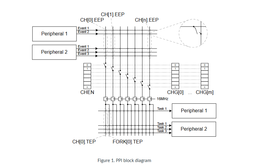
CH[n].EEP (Event Endpoint):
PPI 채널의 이벤트 입력을 설정하는 엔드포인트입니다.
주변 장치(Event)가 발생하면 이 입력을 통해 신호를 수신합니다.
CH[n].TEP (Task Endpoint):
PPI 채널의 작업 출력을 설정하는 엔드포인트입니다.
이벤트가 발생했을 때 이 출력으로 연결된 작업(Task)을 실행합니다.
FORK[n].TEP:
PPI Fork 기능을 통해 하나의 이벤트를 여러 작업(Task)에 연결할 수 있습니다.
예를 들어, 타이머 이벤트를 두 개의 GPIO 핀 제어 작업에 동시에 연결 가능.
CHEN (Channel Enable Register):
특정 PPI 채널을 활성화하거나 비활성화합니다.
이 레지스터를 통해 어떤 채널이 작동할지를 제어합니다.
CHG[m] (Channel Groups):
여러 PPI 채널을 그룹화하여 특정 상황에서 일괄적으로 활성화/비활성화합니다.
하나의 작업으로 여러 채널을 동시에 제어할 때 유용합니다.
Peripheral 1의 동작
- Peripheral 1은 CH[0].EEP에서 이벤트를 받아 CH[0].TEP로 전달됩니다.
- 여기서 FORK[0].TEP가 활성화되지 않았으므로 Fork 기능이 사용되지 않았습니다.
- 결론적으로, Peripheral 1은 단일 이벤트에서 단일 작업으로 연결된 One-to-One 연결만 수행하고 있습니다.
Peripheral 2의 동작
- Peripheral 2는 CH[1].EEP에서 이벤트를 받아 CH[1].TEP로 전달됩니다.
- 이 경우 FORK[1].TEP를 통해 추가적인 작업으로도 이벤트가 전달됩니다.
- 따라서 Peripheral 2는 Fork 기능을 사용하여 하나의 이벤트로 여러 작업(Task)을 수행하고 있습니다.
- 이벤트를 발생시키는 Peripheral과 작업을 수행하는 Peripheral은 서로 다를 수 있습니다. 즉, Peripheral 1의 이벤트가 Peripheral 2의 Task로 연결 될 수 있습니다.
실습
One to One
필요한 라이브러리와 설정 정의
#include <nrfx_example.h>
#include <helpers/nrfx_gppi.h>
#include <nrfx_timer.h>
#include <nrfx_gpiote.h>
#define NRFX_LOG_MODULE                 EXAMPLE
#define NRFX_EXAMPLE_CONFIG_LOG_ENABLED 1
#define NRFX_EXAMPLE_CONFIG_LOG_LEVEL   3
#include <nrfx_log.h>
 // 설정값 정의
#define TIMER_INST_IDX 0            // 사용할 타이머 인스턴스
#define TIME_TO_WAIT_MS 1000UL      // 타이머 대기 시간 (밀리초)
#define GPIOTE_INST_IDX 0           // 사용할 GPIOTE 인스턴스
#define OUTPUT_PIN LED1_PIN         // 제어할 GPIO 핀
-
nrfx_example.h, nrfx_gppi.h 등 라이브러리를 포함하여 GPPI, 타이머, GPIOTE 기능을 사용할 수 있도록 설정.
-
LED 제어와 타이머 대기 시간을 설정.
타이머 이벤트 핸들러
static void timer_handler(nrf_timer_event_t event_type, void *p_context)
{
    if (event_type == NRF_TIMER_EVENT_COMPARE0)
    {
        char *p_msg = p_context;
        NRFX_LOG_INFO("타이머 완료: >%s<", p_msg);
        NRFX_LOG_INFO("GPIO 핀 상태: %d -> %s", OUTPUT_PIN,
                      nrfx_gpiote_in_is_set(OUTPUT_PIN) ? "높음" : "낮음");
    }
}
- 타이머가 설정된 시간에 도달했을 때 호출됨
- 핸들러는 타이머 이벤트와 관련된 로그를 출력
메인 함수 시작 및 초기화
int main(void)
{
    nrfx_err_t status; // 함수 호출 결과 저장
    uint8_t out_channel; // GPIOTE 채널
    uint8_t gppi_channel; // GPPI 채널
    // GPIOTE 초기화
    nrfx_gpiote_t const gpiote_inst = NRFX_GPIOTE_INSTANCE(GPIOTE_INST_IDX);
    status = nrfx_gpiote_init(&gpiote_inst, NRFX_GPIOTE_DEFAULT_CONFIG_IRQ_PRIORITY);
    if (status != NRFX_SUCCESS) return -1; // 초기화 실패 시 종료
}
- GPIOTE 모듈 초기화.
- 초기화 성공 여부를 확인하고 실패 시 프로그램 종료.
GPIO 출력 핀 설정
    // GPIO 출력 핀 설정
    static const nrfx_gpiote_output_config_t output_config =
    {
        .drive = NRF_GPIO_PIN_S0S1,
        .input_connect = NRF_GPIO_PIN_INPUT_DISCONNECT,
        .pull = NRF_GPIO_PIN_NOPULL,
    };
    const nrfx_gpiote_task_config_t task_config =
    {
        .task_ch = out_channel,
        .polarity = NRF_GPIOTE_POLARITY_TOGGLE,
        .init_val = NRF_GPIOTE_INITIAL_VALUE_HIGH,
    };
    status = nrfx_gpiote_output_configure(&gpiote_inst, OUTPUT_PIN, &output_config, &task_config);
    if (status != NRFX_SUCCESS) return -1;
    nrfx_gpiote_out_task_enable(&gpiote_inst, OUTPUT_PIN);
- GPIO 핀을 출력으로 설정하고 초기 값, 드라이브 모드 등을 정의.
- 핀 상태를 토글할 수 있도록 작업(Task)을 설정.
타이머 초기화
    nrfx_timer_t timer_inst = NRFX_TIMER_INSTANCE(TIMER_INST_IDX);
    uint32_t base_frequency = NRF_TIMER_BASE_FREQUENCY_GET(timer_inst.p_reg);
    nrfx_timer_config_t timer_config = NRFX_TIMER_DEFAULT_CONFIG(base_frequency);
    timer_config.bit_width = NRF_TIMER_BIT_WIDTH_32;
    timer_config.p_context = "타이머 컨텍스트";
status = nrfx_timer_init(&timer_inst, &timer_config, timer_handler);
 if (status != NRFX_SUCCESS) return -1;

 nrfx_timer_clear(&timer_inst);

 uint32_t desired_ticks = nrfx_timer_ms_to_ticks(&timer_inst, TIME_TO_WAIT_MS);
 nrfx_timer_extended_compare(&timer_inst, NRF_TIMER_CC_CHANNEL0, desired_ticks,
                             NRF_TIMER_SHORT_COMPARE0_CLEAR_MASK, true);
- 타이머를 초기화하고 1초마다 비교 이벤트를 발생하도록 설정.
- 타이머 이벤트 발생 시 핸들러 호출.
GPPI 채널 설정
    status = nrfx_gppi_channel_alloc(&gppi_channel);
    if (status != NRFX_SUCCESS) return -1;
nrfx_gppi_channel_endpoints_setup(gppi_channel,
        nrfx_timer_compare_event_address_get(&timer_inst, NRF_TIMER_CC_CHANNEL0),
        nrfx_gpiote_out_task_address_get(&gpiote_inst, OUTPUT_PIN));
nrfx_gppi_channels_enable(BIT(gppi_channel));
- GPPI 채널을 할당하고, 타이머 이벤트와 GPIO 작업(Task)을 연결.
- PPI 채널을 활성화하여 이벤트가 발생할 때 작업이 실행되도록 설정.
타이머 시작 및 루프 실행
    nrfx_timer_enable(&timer_inst);
    while (1)
    {
        NRFX_EXAMPLE_LOG_PROCESS(); // 로그 처리
    }
}
- 타이머를 활성화하고, 프로그램이 종료되지 않도록 무한 루프 실행.
전체 코드
#include <nrfx_example.h>
#include <helpers/nrfx_gppi.h>
#include <nrfx_timer.h>
#include <nrfx_gpiote.h>

#define NRFX_LOG_MODULE                 EXAMPLE
#define NRFX_EXAMPLE_CONFIG_LOG_ENABLED 1
#define NRFX_EXAMPLE_CONFIG_LOG_LEVEL   3
#include <nrfx_log.h>

// 타이머 및 GPIO 관련 설정
#define TIMER_INST_IDX 0            // 사용할 타이머 인스턴스
#define TIME_TO_WAIT_MS 1000UL      // 타이머 대기 시간 (밀리초)
#define GPIOTE_INST_IDX 0           // 사용할 GPIOTE 인스턴스
#define OUTPUT_PIN LED1_PIN         // 제어할 GPIO 핀

// 타이머 이벤트 처리 함수
static void timer_handler(nrf_timer_event_t event_type, void *p_context)
{
    if (event_type == NRF_TIMER_EVENT_COMPARE0)
    {
        char *p_msg = p_context;
        NRFX_LOG_INFO("타이머 완료: >%s<", p_msg);
        NRFX_LOG_INFO("GPIO 핀 상태: %d -> %s", OUTPUT_PIN,
                      nrfx_gpiote_in_is_set(OUTPUT_PIN) ? "높음" : "낮음");
    }
}

// 메인 함수
int main(void)
{
    nrfx_err_t status;
    uint8_t out_channel;  // GPIOTE 채널
    uint8_t gppi_channel; // GPPI 채널

#if defined(__ZEPHYR__)
    IRQ_CONNECT(NRFX_IRQ_NUMBER_GET(NRF_TIMER_INST_GET(TIMER_INST_IDX)), IRQ_PRIO_LOWEST,
                NRFX_TIMER_INST_HANDLER_GET(TIMER_INST_IDX), 0, 0);
    IRQ_CONNECT(NRFX_IRQ_NUMBER_GET(NRF_GPIOTE_INST_GET(GPIOTE_INST_IDX)), IRQ_PRIO_LOWEST,
                NRFX_GPIOTE_INST_HANDLER_GET(GPIOTE_INST_IDX), 0, 0);
#endif

    NRFX_EXAMPLE_LOG_INIT();

    NRFX_LOG_INFO("GPPI 1:1 예제 시작");
    NRFX_EXAMPLE_LOG_PROCESS();

    // GPIOTE 초기화
    nrfx_gpiote_t const gpiote_inst = NRFX_GPIOTE_INSTANCE(GPIOTE_INST_IDX);
    status = nrfx_gpiote_init(&gpiote_inst, NRFX_GPIOTE_DEFAULT_CONFIG_IRQ_PRIORITY);
    NRFX_ASSERT(status == NRFX_SUCCESS);
    NRFX_LOG_INFO("GPIOTE 상태: %s",
                  nrfx_gpiote_init_check(&gpiote_inst) ? "초기화됨" : "초기화되지 않음");

    // GPIOTE 채널 할당
    status = nrfx_gpiote_channel_alloc(&gpiote_inst, &out_channel);
    NRFX_ASSERT(status == NRFX_SUCCESS);

    // GPIO 출력 핀 설정
    static const nrfx_gpiote_output_config_t output_config =
    {
        .drive = NRF_GPIO_PIN_S0S1,
        .input_connect = NRF_GPIO_PIN_INPUT_DISCONNECT,
        .pull = NRF_GPIO_PIN_NOPULL,
    };

    const nrfx_gpiote_task_config_t task_config =
    {
        .task_ch = out_channel,
        .polarity = NRF_GPIOTE_POLARITY_TOGGLE,
        .init_val = NRF_GPIOTE_INITIAL_VALUE_HIGH,
    };

    status = nrfx_gpiote_output_configure(&gpiote_inst, OUTPUT_PIN, &output_config, &task_config);
    NRFX_ASSERT(status == NRFX_SUCCESS);
    nrfx_gpiote_out_task_enable(&gpiote_inst, OUTPUT_PIN);

    // 타이머 설정
    nrfx_timer_t timer_inst = NRFX_TIMER_INSTANCE(TIMER_INST_IDX);
    uint32_t base_frequency = NRF_TIMER_BASE_FREQUENCY_GET(timer_inst.p_reg);
    nrfx_timer_config_t timer_config = NRFX_TIMER_DEFAULT_CONFIG(base_frequency);
    timer_config.bit_width = NRF_TIMER_BIT_WIDTH_32;
    timer_config.p_context = "타이머 컨텍스트";

    status = nrfx_timer_init(&timer_inst, &timer_config, timer_handler);
    NRFX_ASSERT(status == NRFX_SUCCESS);
    nrfx_timer_clear(&timer_inst);

    uint32_t desired_ticks = nrfx_timer_ms_to_ticks(&timer_inst, TIME_TO_WAIT_MS);
    NRFX_LOG_INFO("타이머 설정 완료: %lu ms", TIME_TO_WAIT_MS);

    // 타이머 비교 값 설정
    nrfx_timer_extended_compare(&timer_inst, NRF_TIMER_CC_CHANNEL0, desired_ticks,
                                NRF_TIMER_SHORT_COMPARE0_CLEAR_MASK, true);

    // GPPI 채널 설정
    status = nrfx_gppi_channel_alloc(&gppi_channel);
    NRFX_ASSERT(status == NRFX_SUCCESS);

    nrfx_gppi_channel_endpoints_setup(gppi_channel,
        nrfx_timer_compare_event_address_get(&timer_inst, NRF_TIMER_CC_CHANNEL0),
        nrfx_gpiote_out_task_address_get(&gpiote_inst, OUTPUT_PIN));

    nrfx_gppi_channels_enable(BIT(gppi_channel));

    // 타이머 시작
    nrfx_timer_enable(&timer_inst);
    NRFX_LOG_INFO("타이머 상태: %s", nrfx_timer_is_enabled(&timer_inst) ? "활성화됨" : "비활성화됨");

    while (1)
    {
        NRFX_EXAMPLE_LOG_PROCESS(); // 로그 처리
    }
}
Fork
헤더 파일 및 설정값 정의
#include <nrfx_example.h>
#include <helpers/nrfx_gppi.h>
#include <nrfx_timer.h>
#include <nrfx_gpiote.h>
#define TIMER_INST_IDX 0            // 사용할 타이머 인스턴스
#define TIME_TO_WAIT_MS 1000UL      // 타이머 대기 시간 (1초)
#define GPIOTE_INST_IDX 0           // 사용할 GPIOTE 인스턴스
#define OUTPUT_PIN_PRIMARY LED1_PIN // 첫 번째 LED 핀
#define OUTPUT_PIN_FORK LED2_PIN    // 두 번째 LED 핀 (Fork 작업)
Timer 이벤트 핸들러
static void timer_handler(nrf_timer_event_t event_type, void *p_context)
{
    if (event_type == NRF_TIMER_EVENT_COMPARE0)
    {
        char *p_msg = p_context;
        NRFX_LOG_INFO("타이머 완료: >%s<", p_msg);
        NRFX_LOG_INFO("첫 번째 핀 상태: %d -> %s", OUTPUT_PIN_PRIMARY,
                      nrfx_gpiote_in_is_set(OUTPUT_PIN_PRIMARY) ? "높음" : "낮음");
        NRFX_LOG_INFO("두 번째 핀 상태: %d -> %s", OUTPUT_PIN_FORK,
                      nrfx_gpiote_in_is_set(OUTPUT_PIN_FORK) ? "높음" : "낮음");
    }
}
- 타이머가 설정된 시간에 도달하면 호출됩니다.
- 첫 번째 LED와 두 번째 LED의 현재 상태를 로그로 출력합니다.
메인 함수 시작
int main(void)
{
    nrfx_err_t status;  // 함수 실행 성공 여부를 저장
    uint8_t out_channel_primary, out_channel_fork; // 두 GPIO 작업 채널
    uint8_t gppi_channel; // GPPI 채널
- GPIO 작업(Task) 채널과 GPPI 채널을 위한 변수 선언
GPIOTE 초기화 및 핀 설정
    nrfx_gpiote_t const gpiote_inst = NRFX_GPIOTE_INSTANCE(GPIOTE_INST_IDX);  // GPIOTE 인스턴스 생성
    status = nrfx_gpiote_init(&gpiote_inst, NRFX_GPIOTE_DEFAULT_CONFIG_IRQ_PRIORITY); // GPIOTE를 초기화하여 사용 가능 상태로 만듦
// GPIOTE 채널 할당
status = nrfx_gpiote_channel_alloc(&gpiote_inst, &out_channel_primary);
   status = nrfx_gpiote_channel_alloc(&gpiote_inst, &out_channel_fork);
// GPIO 핀 출력 설정
	static const nrfx_gpiote_output_config_t output_config =
  {
      .drive = NRF_GPIO_PIN_S0S1,  // GPIO 핀의 드라이브 강도를 설정
      .input_connect = NRF_GPIO_PIN_INPUT_DISCONNECT,  // GPIO 핀의 입력 연결을 비활성화
      .pull = NRF_GPIO_PIN_NOPULL,  // 핀 내부 풀업/풀다운 저항을 사용하지 않음
  };
// GPIOTE 작업(Task)을 설정
nrfx_gpiote_task_config_t task_config =
 {
     .task_ch = out_channel_primary,  // GPIOTE 작업(Task)을 실행할 채널을 지정
     .polarity = NRF_GPIOTE_POLARITY_TOGGLE,  // 작업(Task) 실행 시 GPIO 핀의 상태를 토글(toggle)
     .init_val = NRF_GPIOTE_INITIAL_VALUE_HIGH, // GPIO 핀의 초기 상태를 HIGH로 설정
 };
status = nrfx_gpiote_output_configure(&gpiote_inst, OUTPUT_PIN_PRIMARY, &output_config, &task_config); // GPIOTE를 사용하여 특정 GPIO 핀을 출력으로 구성
nrfx_gpiote_out_task_enable(&gpiote_inst, OUTPUT_PIN_PRIMARY); // 특정 GPIO 핀의 GPIOTE 작업(Task)을 활성화
task_config.task_ch = out_channel_fork;  // Fork 작업으로 사용될 두 번째 GPIO 핀(Task)을 설정
task_config.init_val = NRF_GPIOTE_INITIAL_VALUE_LOW;  // 핀 초기 값 LOW
status = nrfx_gpiote_output_configure(&gpiote_inst, OUTPUT_PIN_FORK, &output_config, &task_config);  // GPIO 핀을 출력 핀으로 설정
nrfx_gpiote_out_task_enable(&gpiote_inst, OUTPUT_PIN_FORK);  // GPIOTE 작업(Task)을 활성화
- 첫 번째 핀(LED1_PIN)과 두 번째 핀(LED2_PIN)을 출력 핀으로 설정합니다.
- 두 핀은 각각 다른 초기 상태(첫 번째: HIGH, 두 번째: LOW)로 설정됩니다.
TIMER 초기화 및 비교 값 설정
// 타이머 인스턴스 생성 및 기본 설정
    nrfx_timer_t timer_inst = NRFX_TIMER_INSTANCE(TIMER_INST_IDX);  // 타이머 인스턴스를 생성
    uint32_t base_frequency = NRF_TIMER_BASE_FREQUENCY_GET(timer_inst.p_reg); // 사용 중인 타이머의 기본 주파수를 가져옴
	nrfx_timer_config_t timer_config = NRFX_TIMER_DEFAULT_CONFIG(base_frequency); // 타이머의 기본 설정을 초기화
	timer_config.bit_width = NRF_TIMER_BIT_WIDTH_32; // 타이머의 비트 폭을 설정 (32비트)
    timer_config.p_context = "타이머 컨텍스트";  // 사용자 지정 데이터
// 타이머 초기화 및 클리어
	status = nrfx_timer_init(&timer_inst, &timer_config, timer_handler);  // 타이머를 초기화하고 사용할 준비
	nrfx_timer_clear(&timer_inst); // 타이머의 현재 카운터 값을 0으로 초기화
// 타이머 비교 이벤트 설정
	uint32_t desired_ticks = nrfx_timer_ms_to_ticks(&timer_inst, TIME_TO_WAIT_MS); // 밀리초 단위의 시간을 타이머 틱 값으로 변환
    nrfx_timer_extended_compare(&timer_inst, NRF_TIMER_CC_CHANNEL0, desired_ticks,
	NRF_TIMER_SHORT_COMPARE0_CLEAR_MASK, true); // 타이머가 desired_ticks 값에 도달했을 때 이벤트를 발생시키도록 설정
timer_inst: 설정할 타이머 인스턴스.
NRF_TIMER_CC_CHANNEL0NRF_TIMER_CC_CHANNEL0: 비교 채널(여기서는 0번 채널).
desired_ticks: 비교할 타이머 값.
NRF_TIMER_SHORT_COMPARE0_CLEAR_MASK:
타이머가 desired_ticks에 도달하면 타이머 값을 자동으로 초기화.
true: 이벤트 발생 시 인터럽트를 활성화.
- 타이머를 초기화하고 1초에 한 번 비교 이벤트를 발생시키도록 설정합니다.
- 타이머 이벤트 발생 시 timer_handler가 호출됩니다.
GPPI 및 Fork 설정
status = nrfx_gppi_channel_alloc(&gppi_channel);
nrfx_gppi_channel_endpoints_setup(gppi_channel,
nrfx_timer_compare_event_address_get(&timer_inst, NRF_TIMER_CC_CHANNEL0),
nrfx_gpiote_out_task_address_get(&gpiote_inst, OUTPUT_PIN_PRIMARY));
nrfx_gppi_fork_endpoint_setup(gppi_channel,
nrfx_gpiote_out_task_address_get(&gpiote_inst, OUTPUT_PIN_FORK));
nrfx_gppi_channels_enable(BIT(gppi_channel));
- GPPI 채널을 설정하여 타이머 이벤트를 첫 번째 LED와 두 번째 LED 작업에 연결합니다.
- Fork 메커니즘을 사용하여 하나의 이벤트로 두 작업(Task)을 동시에 실행합니다.
타이머 시작
    nrfx_timer_enable(&timer_inst);
    while (1)
    {
        NRFX_EXAMPLE_LOG_PROCESS();
    }
}
- 타이머를 활성화하고 프로그램이 종료되지 않도록 무한 루프를 실행합니다.
전체 코드
#include <nrfx_example.h>
#include <helpers/nrfx_gppi.h>
#include <nrfx_timer.h>
#include <nrfx_gpiote.h>

#define TIMER_INST_IDX 0            // 사용할 타이머 인스턴스
#define TIME_TO_WAIT_MS 1000UL      // 타이머 대기 시간 (1초)
#define GPIOTE_INST_IDX 0           // 사용할 GPIOTE 인스턴스
#define OUTPUT_PIN_PRIMARY LED1_PIN // 첫 번째 LED 핀
#define OUTPUT_PIN_FORK LED2_PIN    // 두 번째 LED 핀 (Fork 작업)

static void timer_handler(nrf_timer_event_t event_type, void *p_context)
{
    if (event_type == NRF_TIMER_EVENT_COMPARE0)
    {
        char *p_msg = p_context;
        NRFX_LOG_INFO("타이머 완료: >%s<", p_msg);
        NRFX_LOG_INFO("첫 번째 핀 상태: %d -> %s", OUTPUT_PIN_PRIMARY,
                      nrfx_gpiote_in_is_set(OUTPUT_PIN_PRIMARY) ? "높음" : "낮음");
        NRFX_LOG_INFO("두 번째 핀 상태: %d -> %s", OUTPUT_PIN_FORK,
                      nrfx_gpiote_in_is_set(OUTPUT_PIN_FORK) ? "높음" : "낮음");
    }
}

int main(void)
{
    nrfx_err_t status;
    uint8_t out_channel_primary, out_channel_fork;
    uint8_t gppi_channel;

    nrfx_gpiote_t const gpiote_inst = NRFX_GPIOTE_INSTANCE(GPIOTE_INST_IDX);
    status = nrfx_gpiote_init(&gpiote_inst, NRFX_GPIOTE_DEFAULT_CONFIG_IRQ_PRIORITY);

    status = nrfx_gpiote_channel_alloc(&gpiote_inst, &out_channel_primary);
    status = nrfx_gpiote_channel_alloc(&gpiote_inst, &out_channel_fork);

    static const nrfx_gpiote_output_config_t output_config =
    {
        .drive = NRF_GPIO_PIN_S0S1,
        .input_connect = NRF_GPIO_PIN_INPUT_DISCONNECT,
        .pull = NRF_GPIO_PIN_NOPULL,
    };

    nrfx_gpiote_task_config_t task_config =
    {
        .task_ch = out_channel_primary,
        .polarity = NRF_GPIOTE_POLARITY_TOGGLE,
        .init_val = NRF_GPIOTE_INITIAL_VALUE_HIGH,
    };

    status = nrfx_gpiote_output_configure(&gpiote_inst, OUTPUT_PIN_PRIMARY, &output_config, &task_config);
    nrfx_gpiote_out_task_enable(&gpiote_inst, OUTPUT_PIN_PRIMARY);

    task_config.task_ch = out_channel_fork;
    task_config.init_val = NRF_GPIOTE_INITIAL_VALUE_LOW;

    status = nrfx_gpiote_output_configure(&gpiote_inst, OUTPUT_PIN_FORK, &output_config, &task_config);
    nrfx_gpiote_out_task_enable(&gpiote_inst, OUTPUT_PIN_FORK);

    nrfx_timer_t timer_inst = NRFX_TIMER_INSTANCE(TIMER_INST_IDX);
    uint32_t base_frequency = NRF_TIMER_BASE_FREQUENCY_GET(timer_inst.p_reg);
    nrfx_timer_config_t timer_config = NRFX_TIMER_DEFAULT_CONFIG(base_frequency);
    timer_config.bit_width = NRF_TIMER_BIT_WIDTH_32;
    timer_config.p_context = "타이머 컨텍스트";

    status = nrfx_timer_init(&timer_inst, &timer_config, timer_handler);
    nrfx_timer_clear(&timer_inst);

    uint32_t desired_ticks = nrfx_timer_ms_to_ticks(&timer_inst, TIME_TO_WAIT_MS);
    nrfx_timer_extended_compare(&timer_inst, NRF_TIMER_CC_CHANNEL0, desired_ticks,
                                NRF_TIMER_SHORT_COMPARE0_CLEAR_MASK, true);

    status = nrfx_gppi_channel_alloc(&gppi_channel);

    nrfx_gppi_channel_endpoints_setup(gppi_channel,
                                      nrfx_timer_compare_event_address_get(&timer_inst, NRF_TIMER_CC_CHANNEL0),
                                      nrfx_gpiote_out_task_address_get(&gpiote_inst, OUTPUT_PIN_PRIMARY));

    nrfx_gppi_fork_endpoint_setup(gppi_channel,
                                  nrfx_gpiote_out_task_address_get(&gpiote_inst, OUTPUT_PIN_FORK));

    nrfx_gppi_channels_enable(BIT(gppi_channel));

    nrfx_timer_enable(&timer_inst);

    while (1)
    {
        NRFX_EXAMPLE_LOG_PROCESS();
    }
}
