Buses


→ 하나의 Wire 집합이 여러 개의 System들을 연결
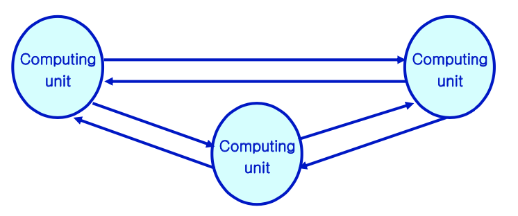
Point to Point

→ 두 Component 사이에 연결 형성하여 Bit 주고 받음
→ 각 Unit에는 Queue(FIFO)가 있음
→ Full Duplex: Data를 주고 받는 것을 동시에 수행 가능
I/O Device Communication
1. Special I/O Instruction
I/O를 처리하기 위한 특별한 명령어를 활용함
→ I/O에만 해당하는 명령어
→ CPU는 각 I/O Port와 연결돼있음
→ Dedicated Port Number를 각 I/O에 부여해 각 Number에 해당하는 명령어를
통해 I/O Communication 이뤄짐
2. Memory-Mapped I/O
각 I/O 기기가 특정 Memory Address에 Mapping됨
I/O를 처리하기 위해, Load/Store Memory를 통해 Mapped Memory Address에 접근하면 됨
→ Bus Decoder가 해당 접근을 I/O로 전달해줌
→ 각 I/O Device가 Data를 확인하여 처리함
I/O Devices의 입출력 Control Logic
1. Polling : Programmed I/O
Input
→ Processor가 계속 I/O Device의 Input이 있는지 확인 ( CPU Cycle 소비 )
→ Input이 있으면 Device에서 Data를 Copy함
Output
→ Processor가 Data를 Device로 Copy하고 처리가 끝날때까지 확인
2. Interrupt Driven I/O
Input
→ I/O Devices가 Processor에 Interrupt 발생시킴
Output
→ Processor가 Data를 Device로 Copy하고 처리가 끝날때까지 확인
💡DMA
Processor가 Output에 대한 처리가 끝날때까지 확인하는 것이 아닌 명령어 수행만을 하고 DMA에게 남은 처리를 맡긴다.
→ CPU가 다른 일을 할 수 있어서 전체적인 성능 ⬆️
