이번에는 ns-3에서 제공하는 CSMA device와 channel을 활용해서 버스 네트워크를 만들어 보겠습니다.
시나리오는 examples/tutorial/second.cc를 사용합니다.
시나리오 분석(second.cc)
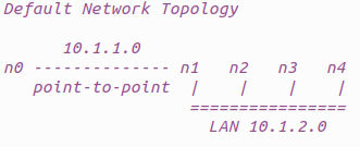
먼저, 우리가 구성할 네트워크의 그림이 그려져있습니다.
이전 예제에서 만든 point-to-point에 bus network를 붙이는 형식입니다.
LAN에는 1개의 공유되는 node(n1)가 있고, 3개의 extra node가 존재합니다.
이제부터 코드를 분석 해보겠습니다.
first.cc와 비슷한 코드들은 간략히 설명하겠습니다.
먼저, logging component를 정의해줍니다.
NS_LOG_COMPONENT_DEFINE ("SecondScriptExample");first.cc와 약간 다른 부분이 있습니다.
verbose flag를 선언하여 logging component를 활성화 할지 말지 결정합니다.(true일 때만 활성화)
그리고 verbose와 nCsma(extra node의 개수)를 command line argument로 변경할 수 있게 선언해줍니다.
마지막 줄은 적어도 1개의 extra node를 보장해줍니다.
bool verbose = true;
uint32_t nCsma = 3;

CommandLine cmd;
cmd.AddValue ("nCsma", "Number of \"extra\" CSMA nodes/devices", nCsma);
cmd.AddValue ("verbose", "Tell echo applications to log if true", verbose);

cmd.Parse (argc, argv);

if (verbose)
{
	LogComponentEnable("UdpEchoClientApplication", LOG_LEVEL_INFO);
	LogComponentEnable("UdpEchoServerApplication", LOG_LEVEL_INFO);
}

nCsma = nCsma == 0 ? 1 : nCsma;
다음은 point-to-point로 연결할 node 2개를 만들어줍니다.
NodeContainer p2pNodes;
p2pNodes.Create (2);
그리고 bus network를 구성할 node들을 만듭니다.
NodeContainer csmaNodes;
csmaNodes.Add (p2pNodes.Get (1));
csmaNodes.Create (nCsma);
두번째 줄에서 point-to-point node 중에서 1번 인덱스의 node(n1)을 가져와 csmaNodes에 추가합니다.
그리고 extra node 개수만큼 새 노드를 생성합니다.
그 결과, n1 node는 2개의 device를 가지게 됩니다.(point-to-point와 csma device)
다음으로 helper를 통해 attribute 설정을 해줍니다.
PointToPointHelper pointToPoint;
pointToPoint.SetDeviceAttribute ("DataRate", StringValue ("5Mbps"));
pointToPoint.SetChannelAttribute ("Delay", StringValue ("2ms"));

NetDeviceContainer p2pDevices;
p2pDevices = pointToPoint.Install (p2pNodes);
그리고 point-to-point node들에 설치하고, net device들을 추적하기 위해 NetDeviceContainer를 사용합니다.
다음으로 CsmaHelper를 사용해 CSMA device와 channel을 생성합니다.
한가지 주의해야할 것은 data rate이 channel의 attribute라는 점입니다.
(이유는 정확히 모르겠습니다. 아래 원문을 참고 부탁드립니다.)
Notice that the data rate is specified by a channel Attribute instead of a device Attribute.
This is because a real CSMA network does not allow one to mix, for example, 10Base-T and 100Base-T devices on a given channel.
CsmaHelper csma;
csma.SetChannelAttribute ("DataRate", StringValue ("100Mbps"));
csma.SetChannelAttribute ("Delay", TimeValue (NanoSeconds (6560)));

NetDeviceContainer csmaDevices;
csmaDevices = csma.Install (csmaNodes);
그리고 csmaNodes에게 설치해줍니다.
이제 node, device, channel이 완성되었지만 protocol stack이 없습니다.
이전과 마찬가지로 helper를 사용해 설치해줍니다.
InternetStackHelper stack;
stack.Install (p2pNodes.Get (0));
stack.Install (csmaNodes);
다음으로 point-to-point device들에게 IP 주소를 할당해줍니다.
Ipv4AddressHelper address;
address.SetBase ("10.1.1.0", "255.255.255.0");
Ipv4InterfaceContainer p2pInterfaces;
p2pInterfaces = address.Assign (p2pDevices);
그리고 CSMA device들에게도 똑같이 할당해줍니다.
address.SetBase ("10.1.2.0", "255.255.255.0");
Ipv4InterfaceContainer csmaInterfaces;
csmaInterfaces = address.Assign (csmaDevices);
이제 topology는 완성되었지만 application이 필요합니다.
이번 예제에서는 CSMA node를 server로, point-to-point node를 client로 설정하겠습니다.
먼저, echo server를 만들어줍니다.
helper를 선언해 포트번호를 9로 설정합니다.
UdpEchoServerHelper echoServer (9);

ApplicationContainer serverApps = echoServer.Install (csmaNodes.Get (nCsma));
serverApps.Start (Seconds (1.0));
serverApps.Stop (Seconds (10.0));
그리고 우리는 마지막 node(n4)를 server로 설정하고 싶습니다.
csmaNodes container를 생각해보면, 0번째는 point-to-point node입니다. 그렇다면 nCsma개의 extra node를 만들었을 경우 마지막 node의 인덱스는 nCsma가 됩니다.
그래서 Get(nCsma)를 해줍니다.
시작, 종료 시간도 설정합니다.
다음으로 client application을 만듭니다.
server로 선정된 nCsma번째 node(마지막 node)의 주소와 포트번호 9를 설정합니다.
그리고 다른 설정들도 해줍니다.
UdpEchoClientHelper echoClient (csmaInterfaces.GetAddress (nCsma), 9);
echoClient.SetAttribute ("MaxPackets", UintegerValue (1));
echoClient.SetAttribute ("Interval", TimeValue (Seconds (1.0)));
echoClient.SetAttribute ("PacketSize", UintegerValue (1024));


ApplicationContainer clientApps = echoClient.Install (p2pNodes.Get (0));
clientApps.Start (Seconds (2.0));
clientApps.Stop (Seconds (10.0));
client는 이전과 동일하게 가장 왼쪽에 있는 point-to-point node(n0)로 설정해줍니다.
이번에는 우리가 'internetwork(point-to-point ~ CSMA)'를 만들었으므로, internetwork routing이 필요합니다.
ns-3에서는 'global routing'이라는 것을 제공합니다.
Ipv4GlobalRoutingHelper::PopulateRoutingTables ();다음으로, tracing을 활성화 해줍니다.
pointToPoint.EnablePcapAll ("second");
csma.EnablePcap ("second", csmaDevices.Get (1), true);
csma에게 PCAP를 활성화해주는 부분이 약간 다릅니다.
CSMA 네트워크는 여러개의 endpoint들이 있습니다. 여기서 trace 정보를 얻는 방법은 크게 2가지가 있습니다.
먼저, 모든 net device들에 대해 각각 trace 파일을 생성하는 방법.
아니면 하나의 device를 선정해 promiscuous mode로 설정하는 것입니다. 그러면 device는 네트워크의 모든 패킷에 대해 'sniff' 하여 하나의 pcap 파일에 저장할 수 있습니다.
우리는 후자를 선택할 것이고, 마지막 인자를 true로 설정해주어 promiscuous mode로 패킷을 잡도록 합니다.
대상 device는 n2(csmaDevices 중 첫번째)로 설정해줍니다.
마지막으로 실행 코드를 넣어줍니다.
Simulator::Run ();
Simulator::Destroy ();
시뮬레이션 실행
$ cp examples/tutorial/second.cc scratch/mysecond.cc
$ ./ns3 build

$ export NS_LOG=""
$ ./ns3 run scratch/mysecond
결과
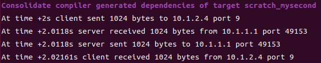
결과를 보면 server가 10.1.2.4에 있음을 알 수 있습니다. 그리고 echo가 잘 되었음을 확인할 수 있습니다.
다음으로, 디렉토리를 보면 trace의 결과 pcap파일이 생성되어 있습니다.
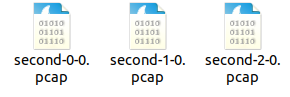
파일 이름의 의미는 <이름>-<node 번호>-<device 번호>.pcap 입니다.
우리가 설정한대로 모든 point-to-point node(n0, n1)와 첫번째 csma node(n2)를 대상으로 잘 되었음을 확인할 수 있습니다.
결과 분석
이제 결과를 분석해보겠습니다.
먼저, n0부터 보겠습니다.
$ tcpdump -nn -tt -r second-0-0.pcap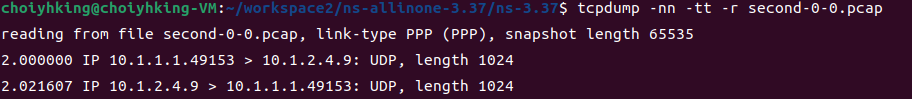
첫번째 줄을 보면, link 타입이 PPP(point-to-point)임을 확인할 수 있습니다. 그리고 server(10.1.2.4)로 패킷을 보내고 받는 모습을 보입니다.
다음으로 옆에 있는 n1을 보겠습니다.
$ tcpdump -nn -tt -r second-1-0.pcap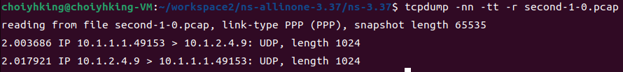
마찬가지로 PPP link이고, n0에서 2.000초에 보내진 패킷이 2.003686초에 지나갔음을 확인할 수 있습니다.
마지막으로, promiscuous mode인 n2를 보겠습니다.
$ tcpdump -nn -tt -r second-2-0.pcap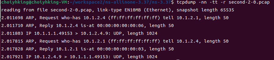
link type이 Ethernet임을 확인할 수 있습니다.
그리고 n1에서는 패킷을 보낼 IP 주소(10.1.2.4)는 알고있지만, MAC 주소는 모릅니다. 그래서 ARP(Address Resolution Protocol)이 필요합니다.
n1은 CSMA 네트워크에 broadcast 해서 IP 주소 10.1.2.4를 가진 device를 찾습니다. 그리고 n4가 자신의 MAC 주소를 대답하게 됩니다.
(n2는 이 과정에 직접적으로 포함되어있지는 않지만, sniffing 하는 중이어서 모든 트래픽을 가져옵니다.)
❗❗초보자의 수준에서 작성 된 글입니다❗❗
잘못 된 내용이 있으면 피드백 부탁드립니다.