week4
2023.02.03
17:05-20:50
🔥 목표
- C 언어로 LED 제어하는 코드 작성 후 아두이노 실습(with 스위치)
- LED + 스위치 (교재 2주차 내용)
- C 언어로 LCD 제어하는 코드 작성 후 아두이노 실습
- 1602 IIC I2C LCD (교재 5주차 내용)
- C 언어로 7-segment 제어하는 코드 작성 후 아두이노 실습
- 7segment (교재 5주차 내용)
💡 회의 내용
아두이노 코드 C 언어로 작성해서 LED + 스위치 추가해서 LED 제어하기
🖥️ 소스 코드
int buttonPin = 2;
boolean state = LOW;
boolean previousState = LOW;

void setup(){
   pinMode(buttonPin,INPUT);
   Serial.begin(9600);
}
void loop(){
   previousState = state;
   state = digitalRead(buttonPin);

   if(previousState = state;
   state = digitalRead(buttonPin);

   if(previousState == LOW && state == HIGH){
      Serial.println("Push On!");
   }else if(previousState == HIGH && state ==LOW){
      Serial.println("Push Off!");
   }
   delay(20);
}
int buttonPin = 2;
boolean state = LOW;
boolean previousState = LOW;
void setup(){
pinMode(buttonPin,INPUT);
Serial.begin(9600);
}
void loop(){
previousState = state;
state = digitalRead(buttonPin);
if(previousState = state;
state = digitalRead(buttonPin);
if(previousState == LOW && state == HIGH){
Serial.println("Push On!");
}else if(previousState == HIGH && state ==LOW){
Serial.println("Push Off!");
}
delay(20);
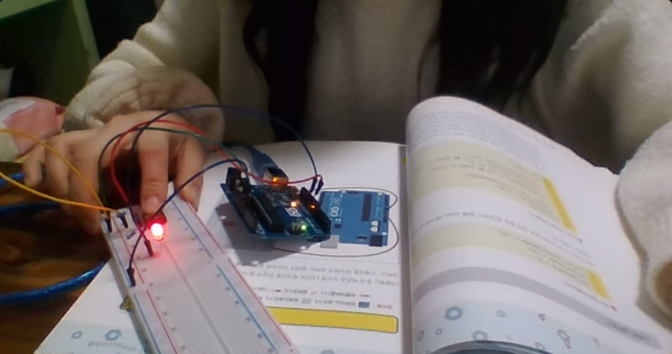
}⬇️ 푸쉬 + LED 출력 예시
아두이노 코드 C 언어로 작성해서 LED 7-세그먼트 제어하기
교재에 없는 내용으로, 아래의 링크를 참고하여 스터디를 진행했습니다.
💡 보드 연결
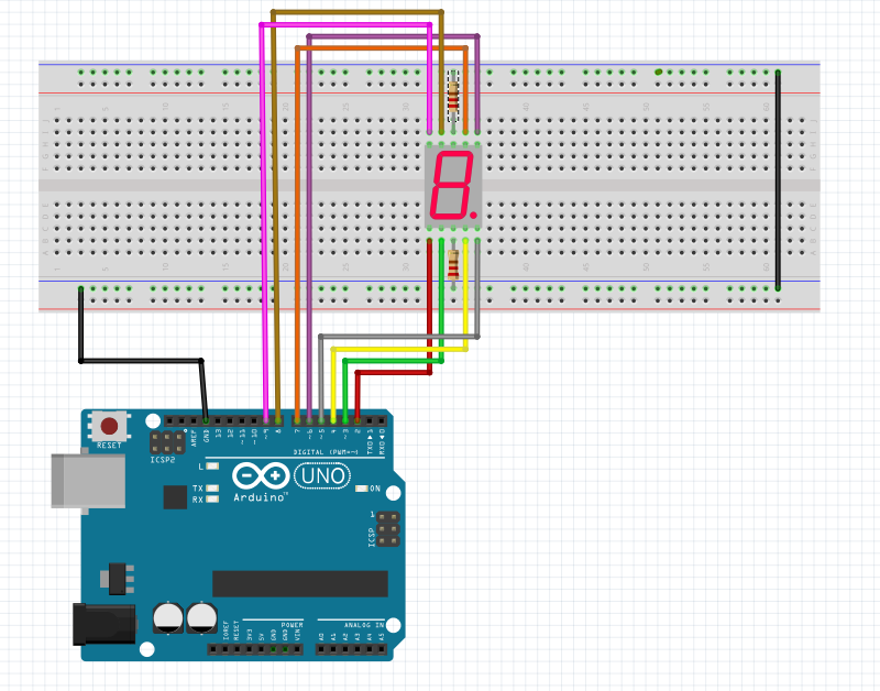
🖥️ 소스 코드
/*
제목 : 7세그먼트로 숫자 표시하기
내용 : 7세그먼트를 사용하여 0부터 9까지 숫자를 표시해 봅시다.
*/
// 7세그먼트는 총 8개의 LED로 구성이 되어 있습니다.
// 본 예제에서는 캐소드(Common Cathode) 타입을 사용하므로, HIGH(1) 값으로 설정합니다.
// 켜고자 하는 LED의 핀에 HIGH(1) 값을 보내도록 설정합니다.
// 반대로, 공통 애노드(Common Anode) 타입의 7세그먼트을 사용할 경우, LOW(0) 값으로 설정합니다.
// 7세그먼트 각각 LED에 핀을 할당합니다. {A, B, C, D, E, F, G, H}
int segmentLEDs[] = {7, 6, 4, 3, 2, 8, 9, 5};
// 지정된 LED 개수
int segmentLEDsNum = 8;
// 각 숫자에 대한 LED 설정 값을 정의합니다.
// 숫자에 매칭되는 LED의 로직레벨을 LOW(0) 상태로 설정합니다.
int digitForNum[10][8] = {
// {A, B, C, D, E, F, G, H}
{1, 1, 1, 1, 1, 1, 0, 0}, //0
{0, 1, 1, 0, 0, 0, 0, 0}, //1
{1, 1, 0, 1, 1, 0, 1, 0}, //2
{1, 1, 1, 1, 0, 0, 1, 0}, //3
{0, 1, 1, 0, 0, 1, 1, 0}, //4
{1, 0, 1, 1, 0, 1, 1, 0}, //5
{1, 0, 1, 1, 1, 1, 1, 0}, //6
{1, 1, 1, 0, 0, 0, 0, 0}, //7
{1, 1, 1, 1, 1, 1, 1, 0}, //8
{1, 1, 1, 1, 0, 1, 1, 0} //9
};
// 실행시 가장 먼저 호출되는 함수이며, 최초 1회만 실행됩니다.
// 변수를 선언하거나 초기화를 위한 코드를 포함합니다.
void setup() {
// 7세그먼트 각각 LED에 연결된 핀을 OUTPUT으로 설정합니다.
for (int i = 0 ; i < segmentLEDsNum ; i++) {
pinMode(segmentLEDs[i], OUTPUT);
}
}
// setup() 함수가 호출된 이후, loop() 함수가 호출되며,
// 블록 안의 코드를 무한히 반복 실행됩니다.
void loop() {
// 0부터 9까지 숫자를 순서대로 표시합니다.
for (int i = 0 ; i < 10 ; i++) {
// 각 숫자에 대한 각각 LED의 로직레벨을 설정합니다.
for (int j = 0 ; j < segmentLEDsNum ; j++) {
digitalWrite(segmentLEDs[j], digitForNum[i][j]);
}
// 1초 동안 대기합니다.
delay(1000);
}
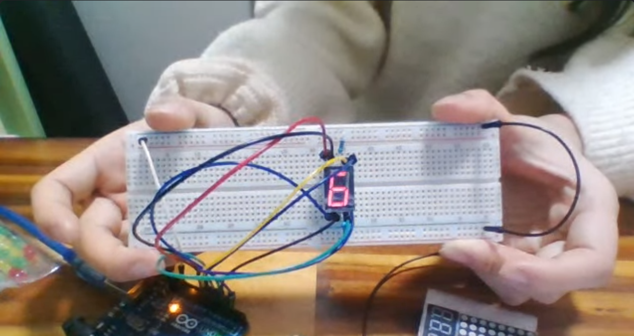
}⬇️ 출력 예시
아두이노 코드 C 언어로 작성해서 LCD 제어하기
교재에 없는 내용으로, 아래의 링크를 참고하였습니다.
아두이노 LCD 1602 IIC연결방식으로 글자표기하기 - 송파 메이커스페이스
-
먼저, I2C LCD를 제어하기 위해 라이브러리를 설치해야 합니다. (필수)
-
아래의 링크에 접속하여 [LiquidCrystal L2C 라이브러리 zip] 파일를 다운로드합니다.
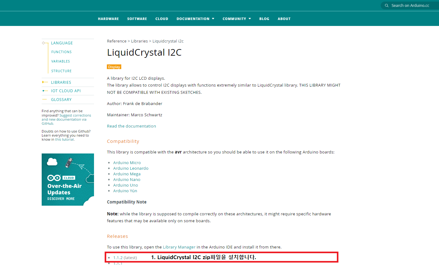
-
1번에서 설치한 라이브러리를 사용하려면 Arduino IDE가 컴퓨터의 저장공간에 접근할 수 있어야 합니다. 이를 위한 [Bridge for Arduino library manager]를 설치합니다.
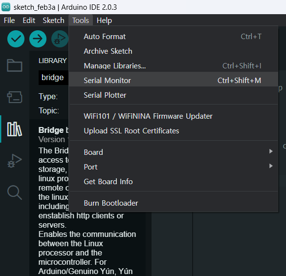
(1) Arduino IDE에서 [Sketch]-[Include Library]-[Manager Libraries] 또는 단축키Ctrl+Shift+i
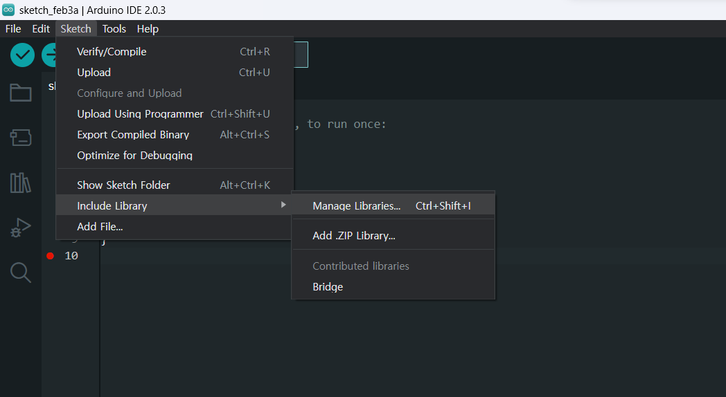
(2) bridge 를 검색하여 Bridge by Arduino를 설치합니다.
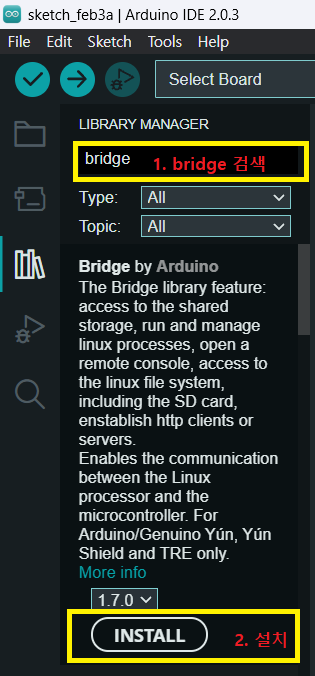
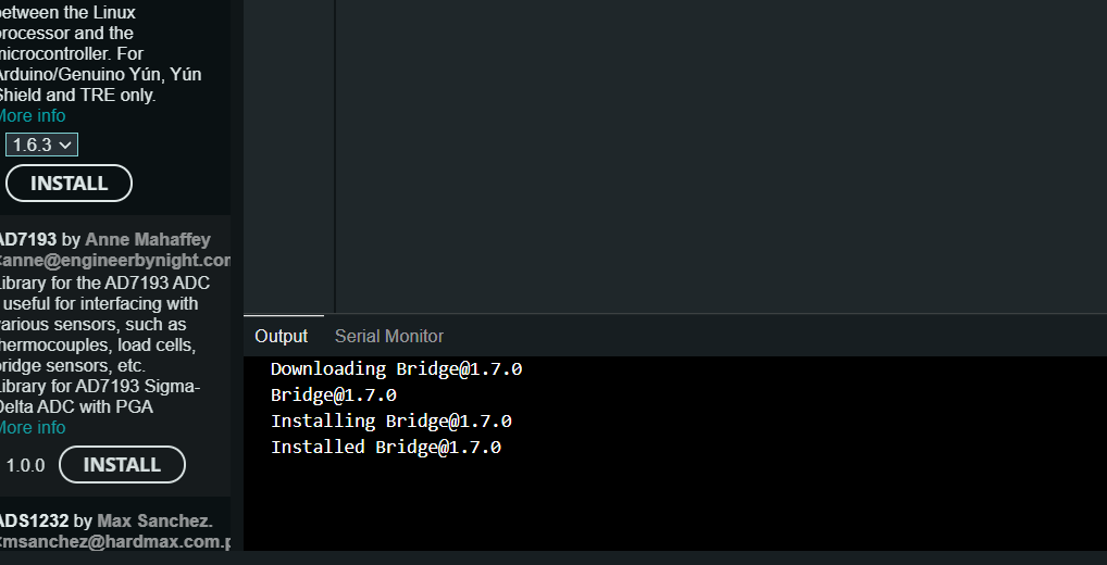
⬇️ 성공적으로 설치된 화면
-
이제 LiquidCrystal l2C 라이브러리를 사용할 수 있도록 zip 파일을 찾습니다.
(1) [Sketch] - [Include Library] - [Add .ZIP Library]
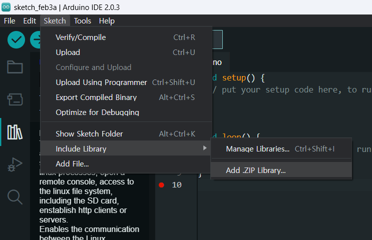
(2) 1번에서 다운로드한 zip파일을 선택하여 [열기]를 클릭하여 완료합니다.
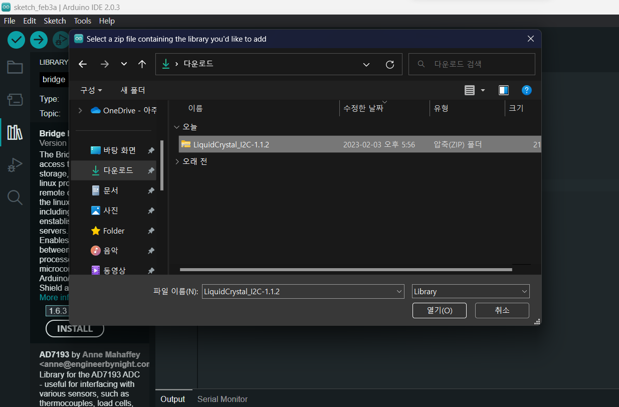
⬇️ 성공적으로 설치된 화면
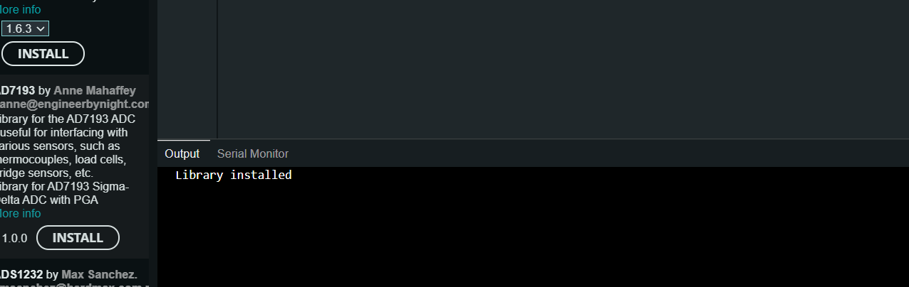
라이브러리 설치 완료.
-
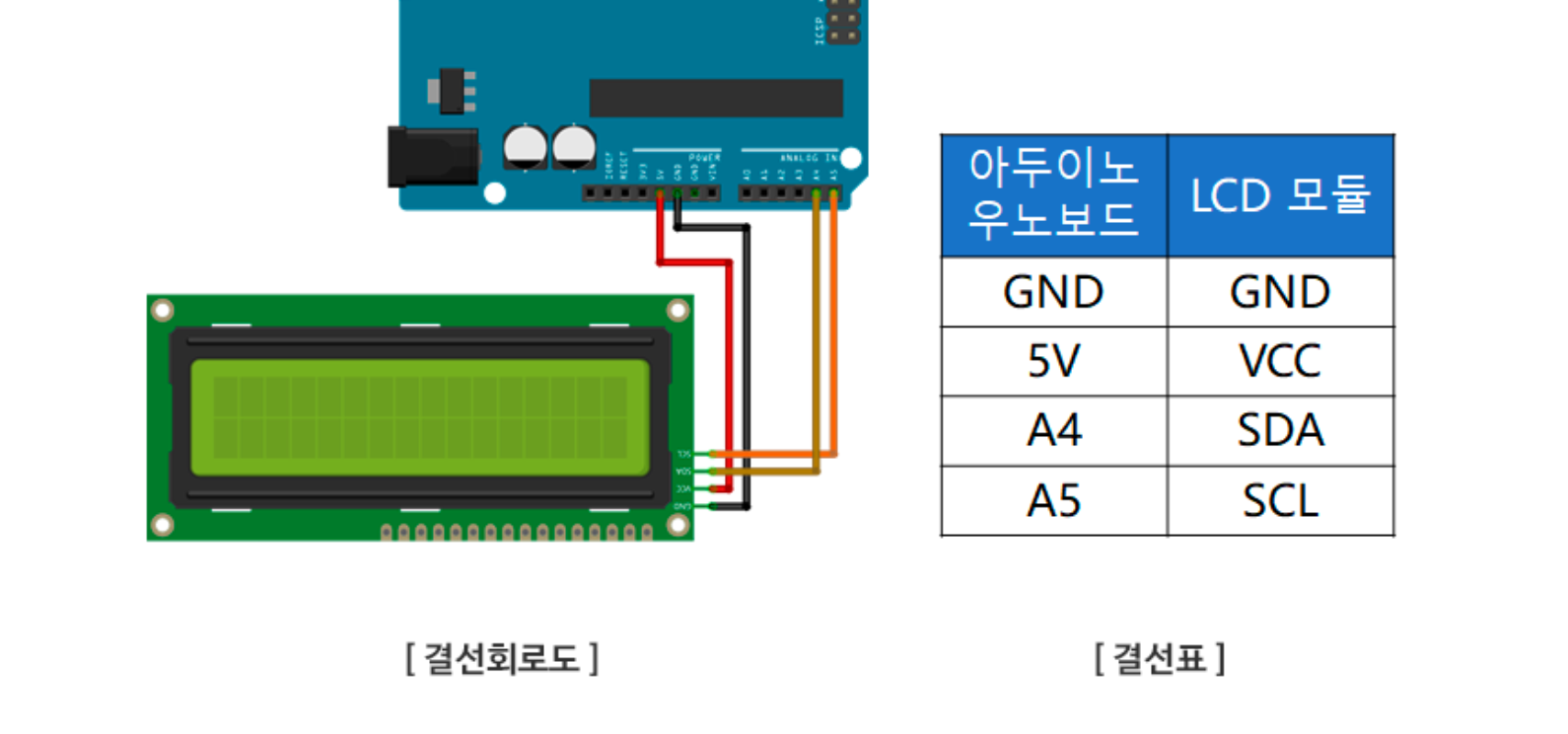
💡 보드 연결
🖥️ 소스 코드
#include <Wire.h>
#include <LiquidCrystal_I2C.h>
LiquidCrystal_I2C lcd(0x27,16,2); // lcd(접근주소, lcd 열의 수, lcd 행의 수)
void setup()
{
lcd.init();
lcd.backlight();
lcd.setCursor(0,0); //0행 0열에 커서 set
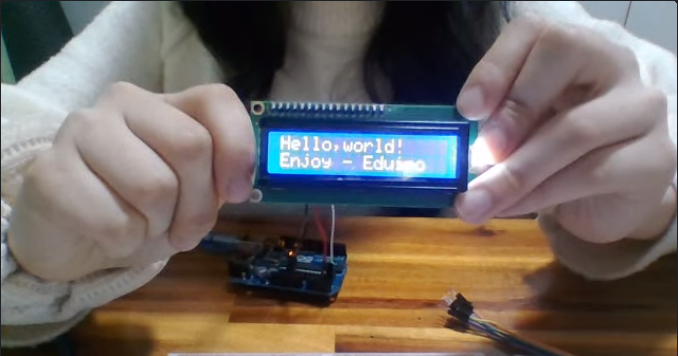
lcd.print("Hello,world!"); // LCD 모니터에 출력
lcd.setCursor(0,1); //0행 1열에 커서 set
lcd.print("Enjoy - APPA"); // LCD 모니터에 출력
}
void loop()
{
}-
LiquidCrystal_I2C lcd(0x27,16,2); ➡️ lcd(접근주소, lcd 열의 수, lcd 행의 수)
(1) 접근주소는 0x27 또는 0x3F입니다.
접근주소 확인 방법: 아래의 l2C 스캐너 코드를 Sketch에서 컴파일-로딩하면 Serial monitor에서 확인할 수 있습니다.
- l2C 주소 확인 및 스캐너 코드
  // --------------------------------------
  // i2c_scanner
  //
  // Version 1
  //    This program (or code that looks like it)
  //    can be found in many places.
  //    For example on the Arduino.cc forum.
  //    The original author is not know.
  // Version 2, Juni 2012, Using Arduino 1.0.1
  //     Adapted to be as simple as possible by Arduino.cc user Krodal
  // Version 3, Feb 26  2013
  //    V3 by louarnold
  // Version 4, March 3, 2013, Using Arduino 1.0.3
  //    by Arduino.cc user Krodal.
  //    Changes by louarnold removed.
  //    Scanning addresses changed from 0...127 to 1...119,
  //    according to the i2c scanner by Nick Gammon
  //    https://www.gammon.com.au/forum/?id=10896
  // Version 5, March 28, 2013
  //    As version 4, but address scans now to 127.
  //    A sensor seems to use address 120.
  // Version 6, November 27, 2015.
  //    Added waiting for the Leonardo serial communication.
  //
  //
  // This sketch tests the standard 7-bit addresses
  // Devices with higher bit address might not be seen properly.
  //

  #include <Wire.h>


  void setup()
  {
    Wire.begin();

    Serial.begin(9600);
    while (!Serial);             // Leonardo: wait for serial monitor
    Serial.println("\nI2C Scanner");
  }


  void loop()
  {
    byte error, address;
    int nDevices;

    Serial.println("Scanning...");

    nDevices = 0;
    for(address = 1; address < 127; address++ )
    {
      // The i2c_scanner uses the return value of
      // the Write.endTransmisstion to see if
      // a device did acknowledge to the address.
      Wire.beginTransmission(address);
      error = Wire.endTransmission();

      if (error == 0)
      {
        Serial.print("I2C device found at address 0x");
        if (address<16)
          Serial.print("0");
        Serial.print(address,HEX);
        Serial.println("  !");

        nDevices++;
      }
      else if (error==4)
      {
        Serial.print("Unknown error at address 0x");
        if (address<16)
          Serial.print("0");
        Serial.println(address,HEX);
      }
    }
    if (nDevices == 0)
      Serial.println("No I2C devices found\n");
    else
      Serial.println("done\n");

    delay(5000);           // wait 5 seconds for next scan
  }
위 코드 실행 후 [tools] - [serial monitor] 클릭 후 하단의 Serial monitor에서 확인
(2) LCD 모니터의 열과 행 수는 부품명을 통해 확인할 수 있습니다.
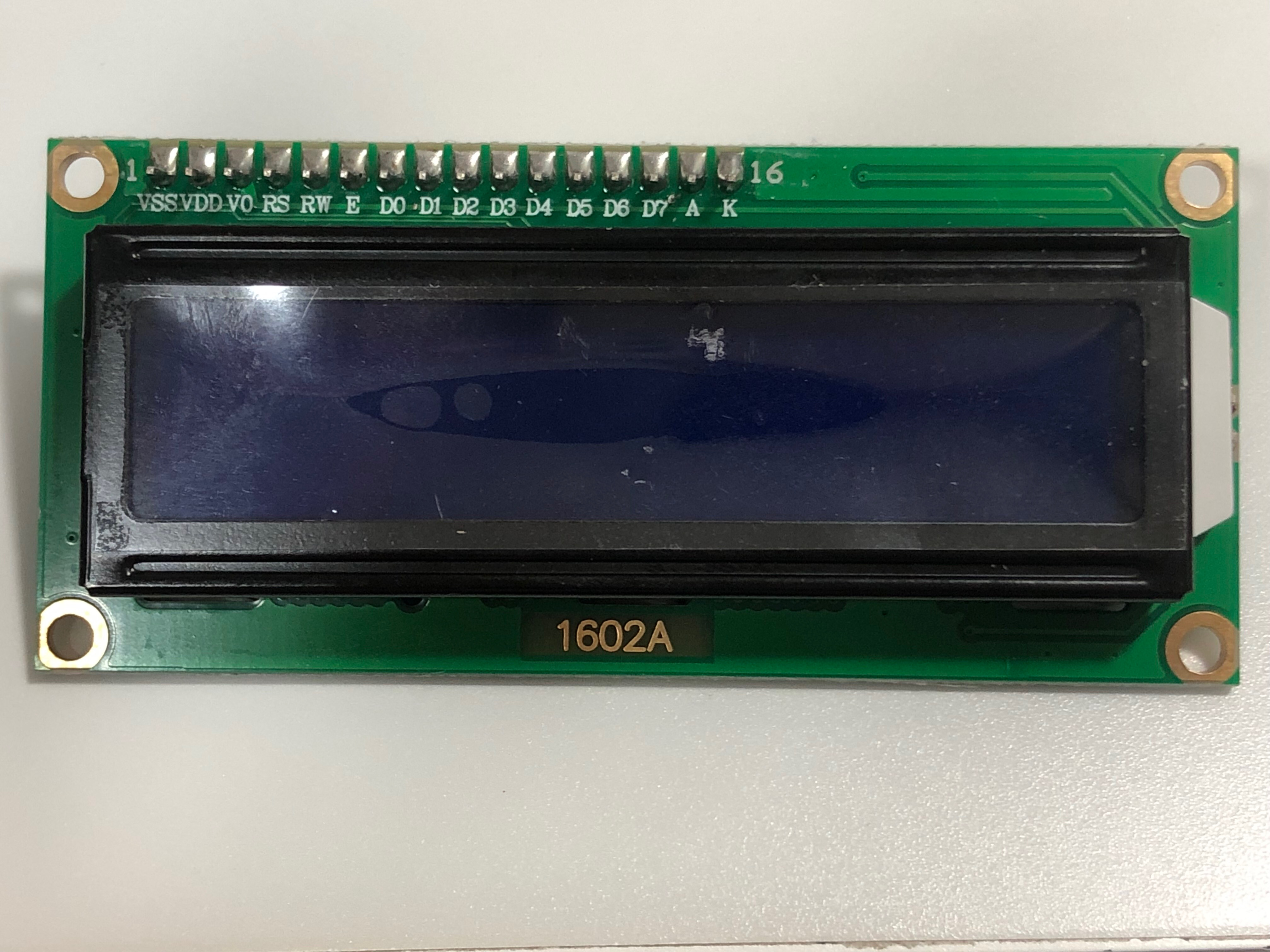
- l2C 주소 확인 및 스캐너 코드
1602A ➡️ 2행 16열
⬇️ 출력 예시
💥문제와 해결 과정
LCD 화면 글자 미출력
코드도 정확히 입력하고, 회로도 제대로 연결했는데도 LCD에 글자가 출력되지 않아 이를 해결할 수 있는 방법에 대해 알아보았다.
⚠️ 글자가 출력되지 않을 때
ex) 화면만 반짝, 네모칸만 출력, 네모칸과 글자 함께 출력, …
-
l2C 주소를 확인합니다.
-
주소가 맞는데도 출력되지 않을 시 저항값의 세기를 조절합니다.
lcd 모니터를 뒤집어 파란색 블럭안에 있는 십자 나사를 세밀하게 조정하여 저항값을 조절하고 변화가 보이면 아두이노를 재연결합니다.
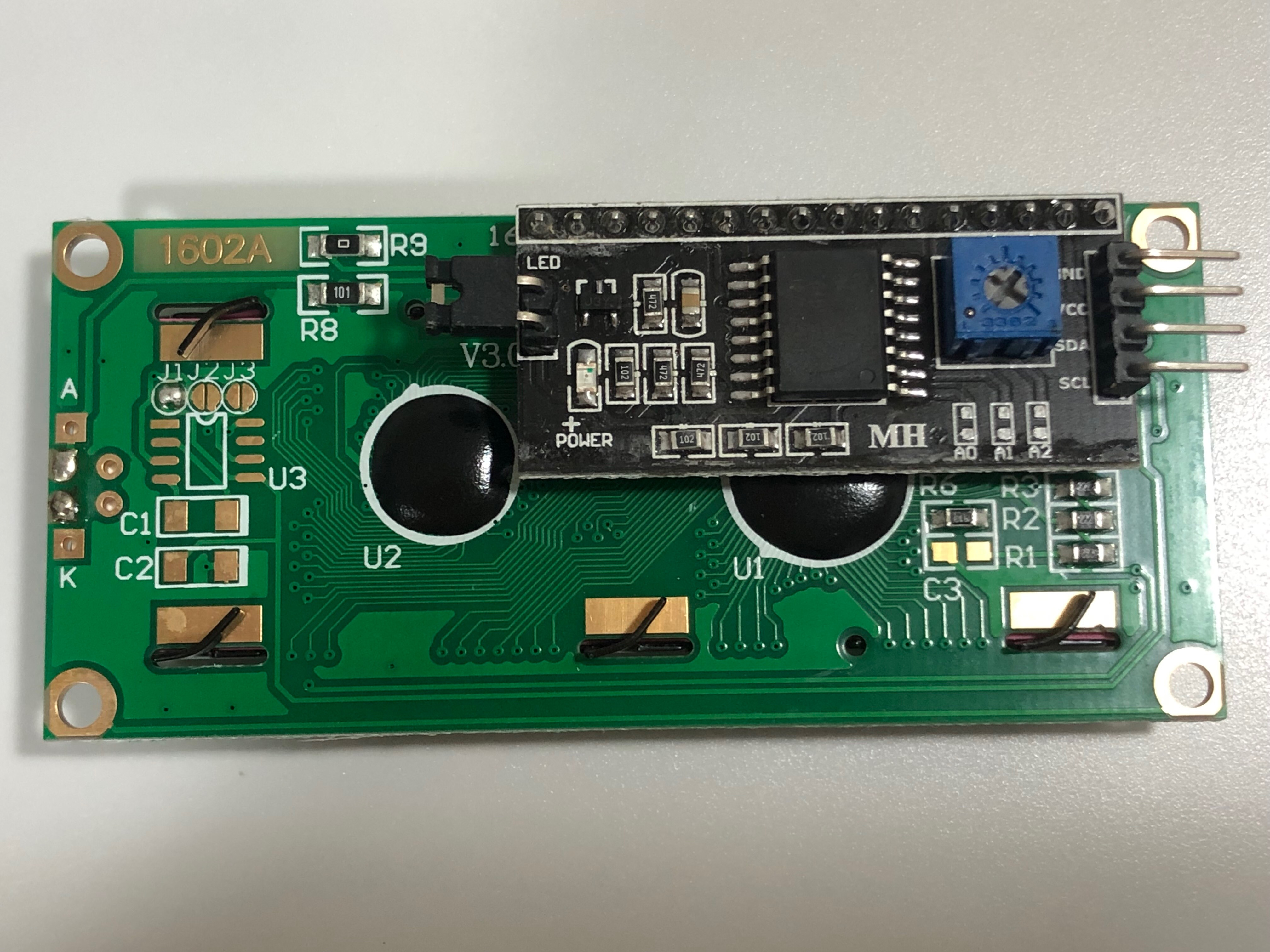
⬇️ 아래 사이트 참고
7 segment
7segment의 종류에 따라 a, b, c, d, e, f, g로 나타나는 부분이 다르므로 이를 확인한 후 회로를 연결하고 코드를 짜야 원하는 대로 작동할 수 있었다.
