1. SPI란?
- Serial Peripheral interface(SPI)
- Synchronous serial communication interface for short-distance communication
- SPI devices can communicate in full duplex mode using a master-slave architecture
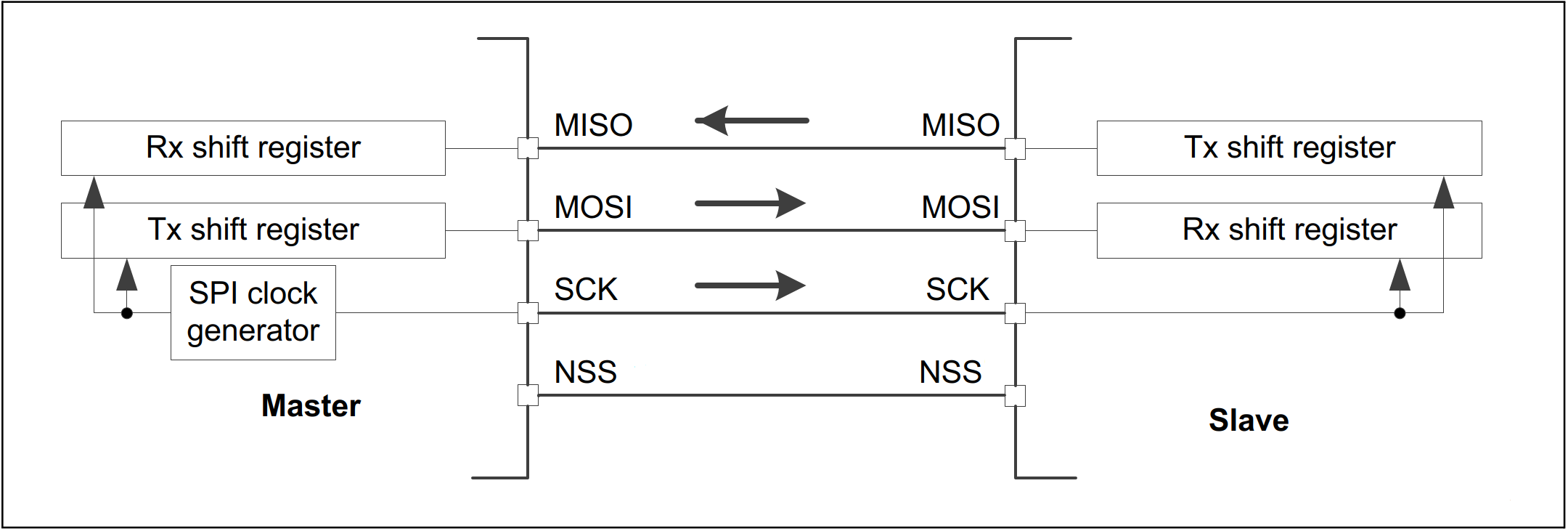
- Each device internally uses a shift register for serial communication -> forms an inter-chip circular buffer

In full duplex mode with multiple slaves, SPI uses four buses:
SCK (Serial clock) bus, controlled by the master device
MISO (Master Input Slave Output) bus
MOSI (Master Output Slave input) bus
SS (Slave Select) bus, useful in the case of a multiple-slave configuration
SS active low signal, so a low voltage means "selected", while a high voltage means "not selected"
If a single slave device is used, its SS pin may be fixed to logic low if the slave permits it.
1.1 STM32 SPI modes
Full duplex
Half duplex
Receive only
Transmit only
1.2 STM32 SPI parameters
Basic parameters:
Frame format: Motorola or TI
Data size: 4 to 16 bits depending on STM32
First bit: MSB or LSB
Clock parameters:
Prescaler: from 2 to 256. --> 2부터 시작하는 이유 : 내부 bus frequency보다 clock speed가 넘어서면 안됨
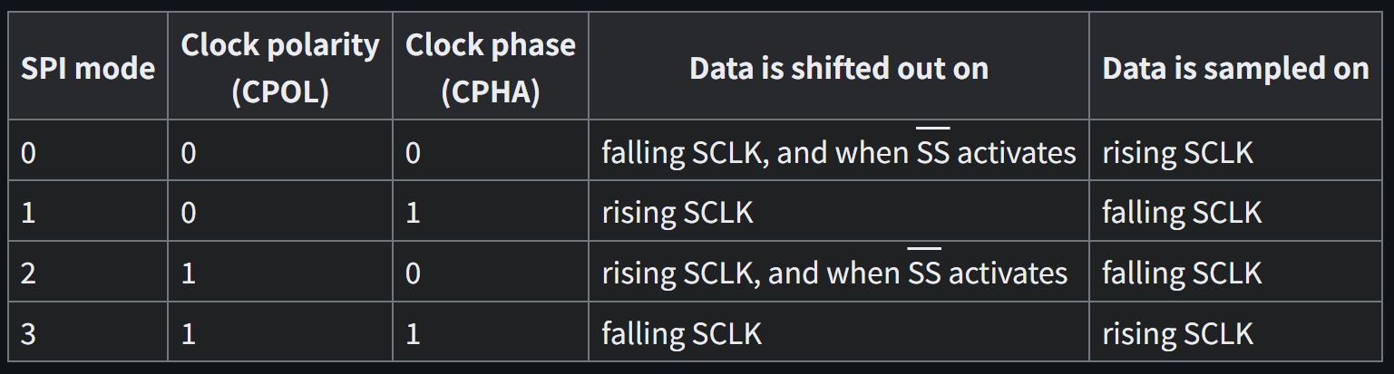
Clock polarity (CPOL) : low or high
Clock phase (CPHA) : 1 or 2 edge
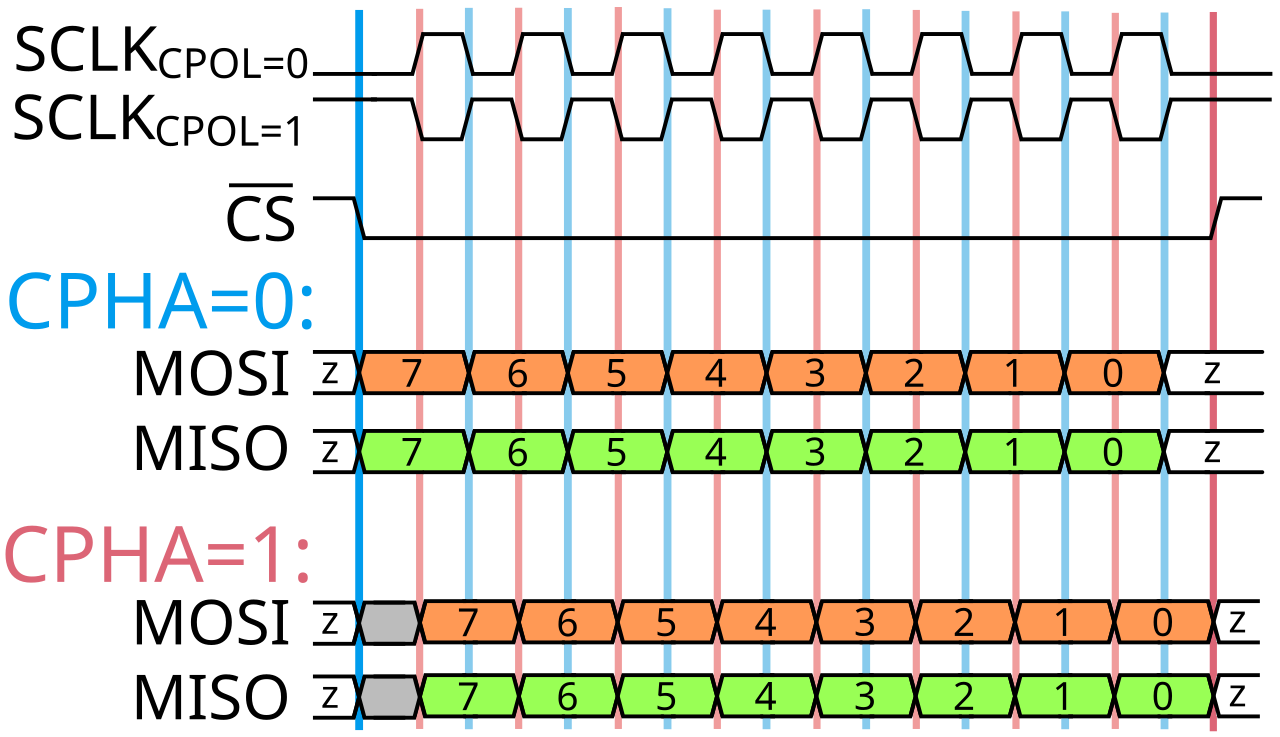
CPOL는 CLK이 시작부터 어떤 값으로 시작할것인가를 나타냄, 예를 들어 CPOL값이 0로 set되면 주파수가 low level부터 시작하고, 1로 set되면 주파수가 high level로 시작한다.
CPHA는 그림으로 보면 CPHA 0이면 CS신호의 변화가 있는 동시에 바로 DATA를 보내고 쓰고있고, CPHA 값이 1이면 CS신호의 변화가 있고나서 주파수의 엣지 트리거링이 발생하는 시점에 시작한다.
그러므로 모드는 총 4개가 나옴, Data Read 방식도 4가지 -> 예를들어 CPOL = 0 , CPHA = 0이면 CS신호가 바뀌면 데이터를 보내기 시작하고 CLK의 상승엣지에서 Data를 Read함
CPHA 1Edge->첫번째 edge에서 데이터를 read함, 2Edge 2번째 edge에서 데이터를 read함
1.3 Main SPI HAL functions
Blocking mode:
communication is performed in polling mode
Polling mode란? cpu가 주기적으로 장치나 메모리 상태를 직접 확인해서 작업을 처리하는 방법
Non-blocking modes:
-
Interrupt mode:
HAL_SPI_Transmit_IT()
HAL_SPI_Receive_IT()
HAL_SPI_TransmitReceive_IT() -
DMA mode:
HAL_SPI_Transmit_DMA()
HAL_SPI_Receive_DMA()
HAL_SPI_TransmitReceive_DMA()
2. HMC SPI Spec
Features
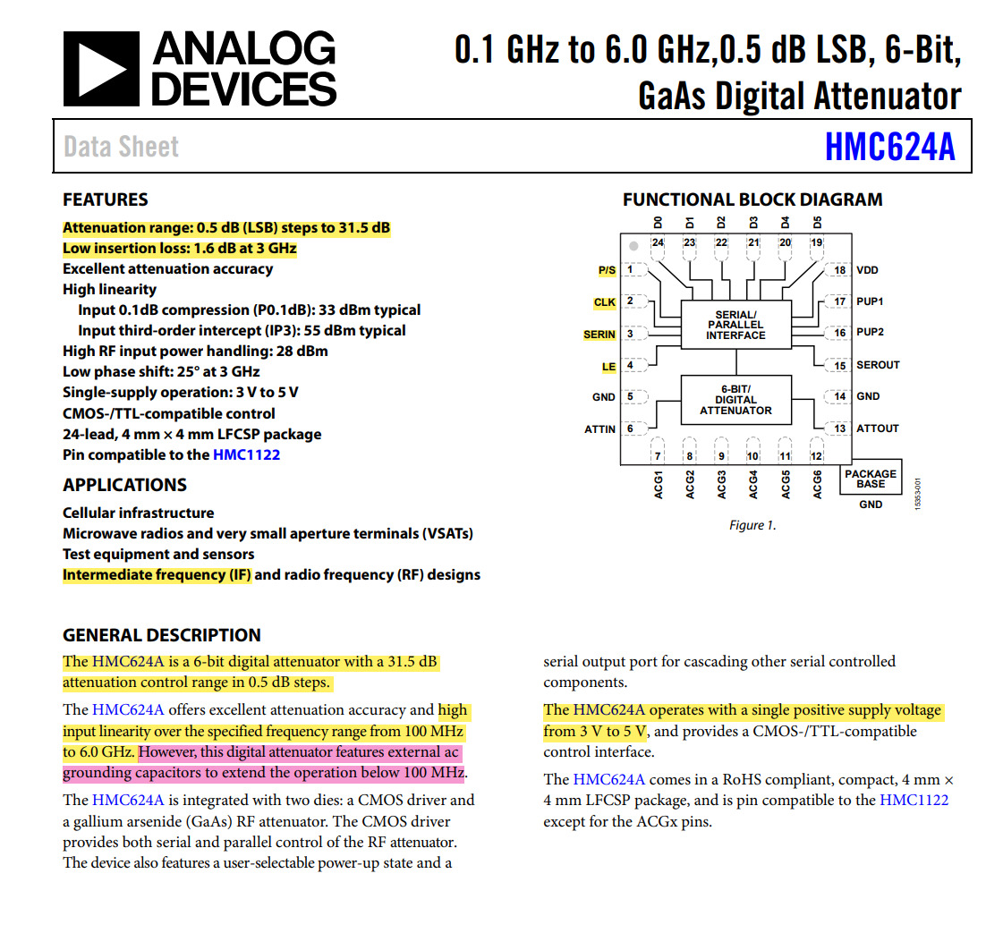
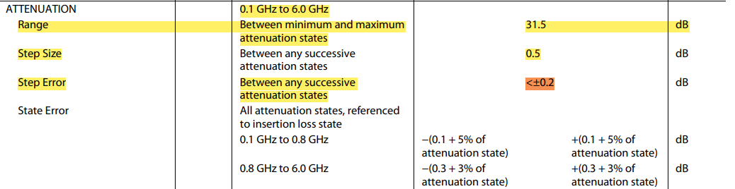
Parameter
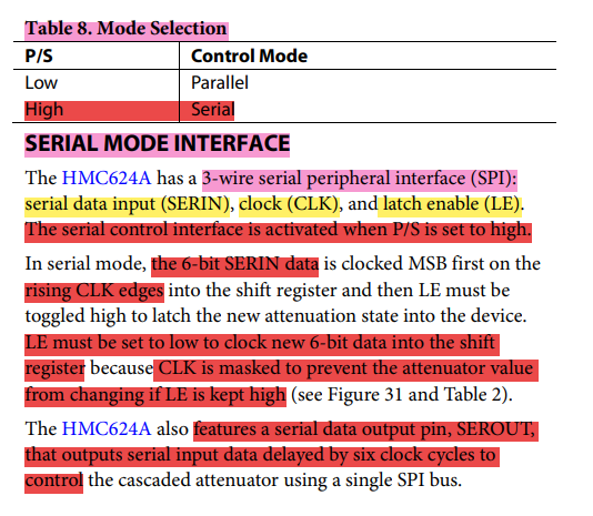
HMC Serial mode interface
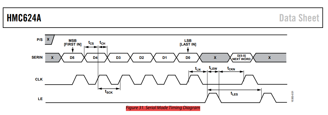
HMC SPI timing Diagram
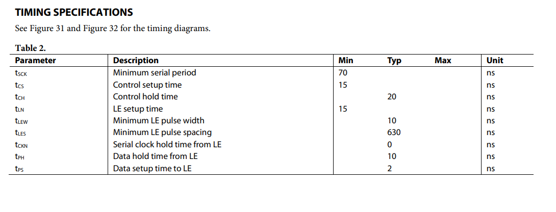
HMC SPI timing specification
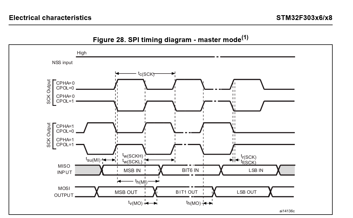
3. STM32 SPI MASTER timing diagram
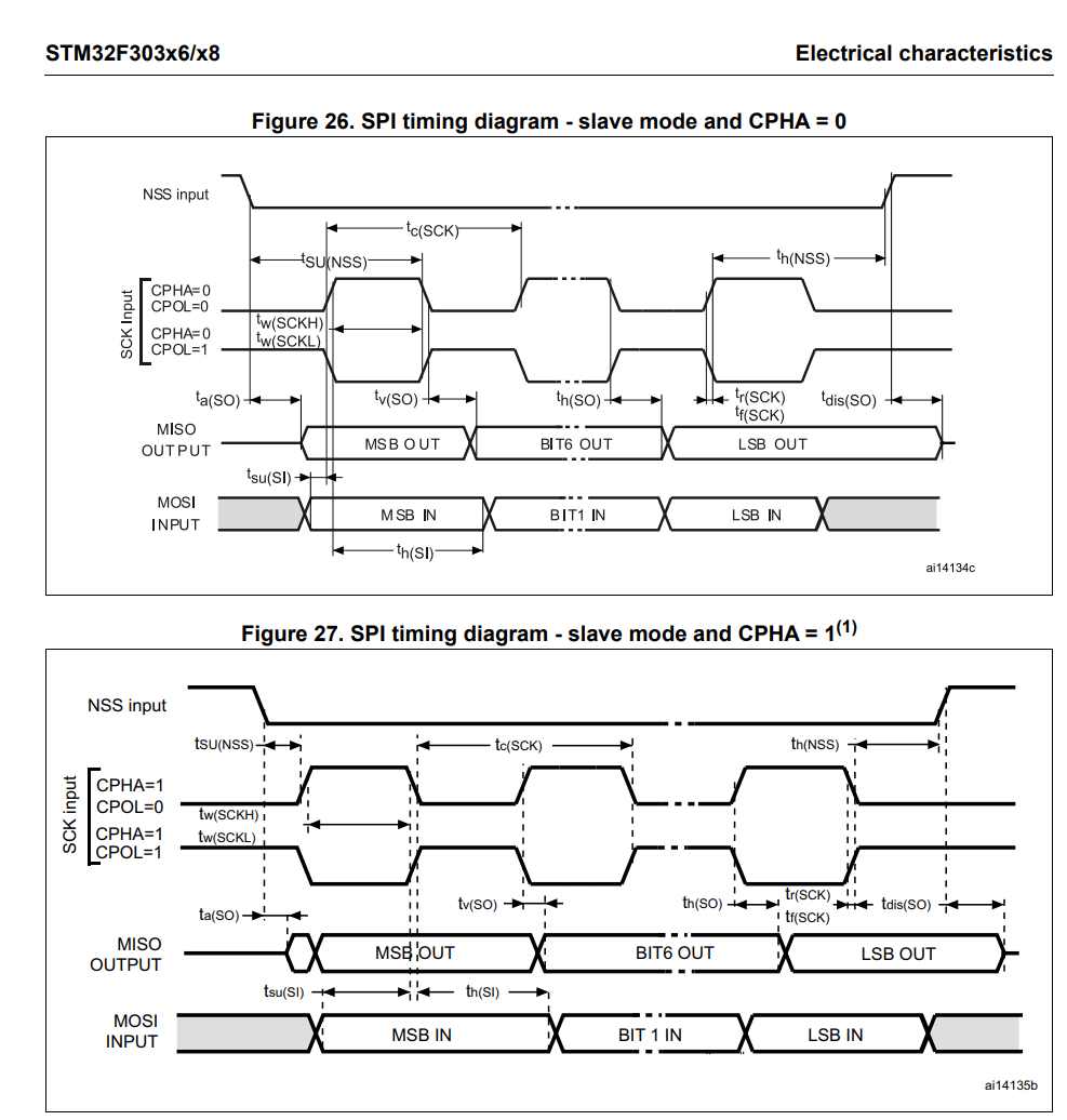
4. STM32 SPI SLAVE timing diagram
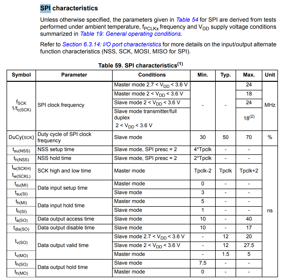
5. STM32 SPI characteristics
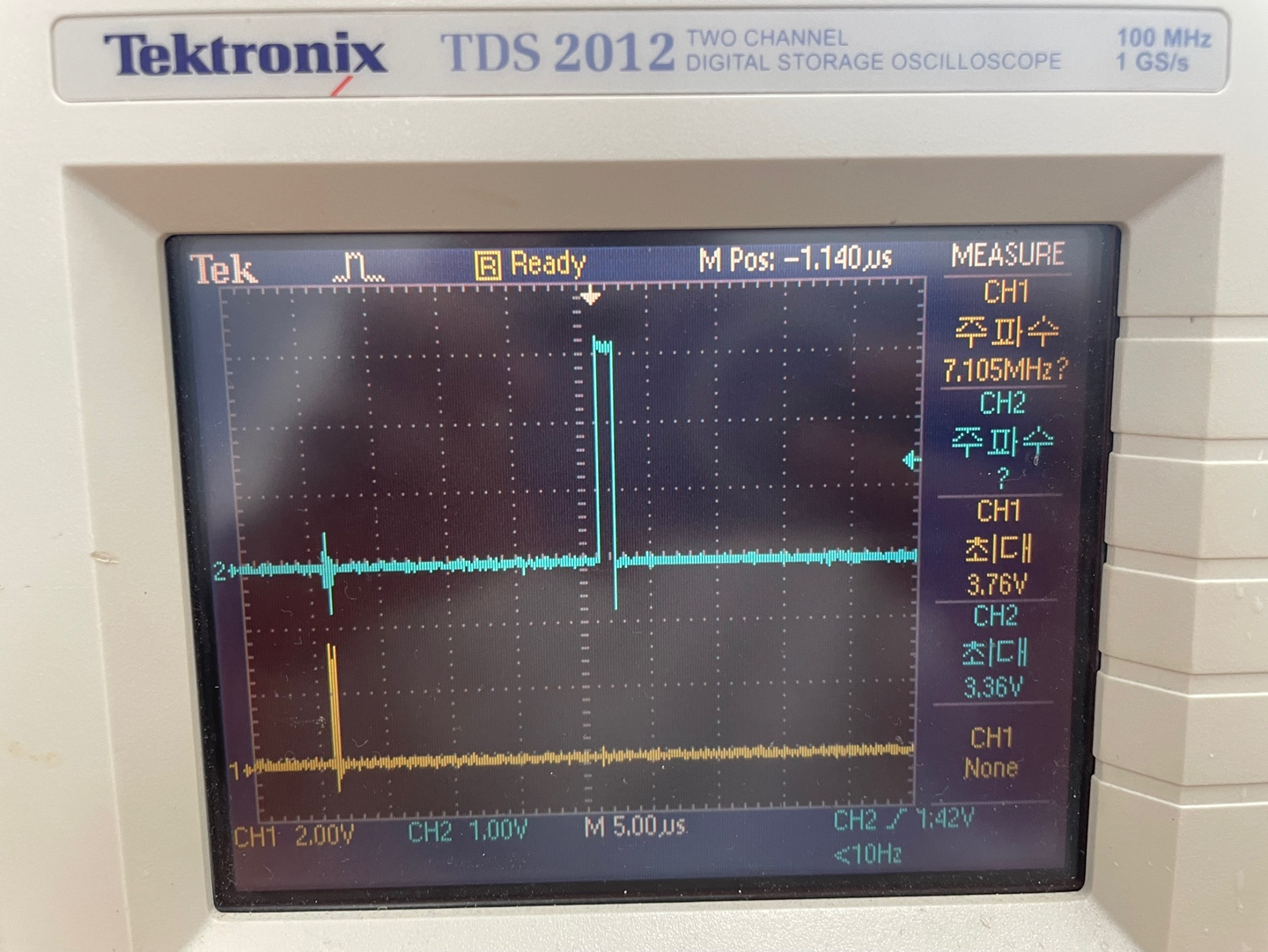
6. SPI signal test
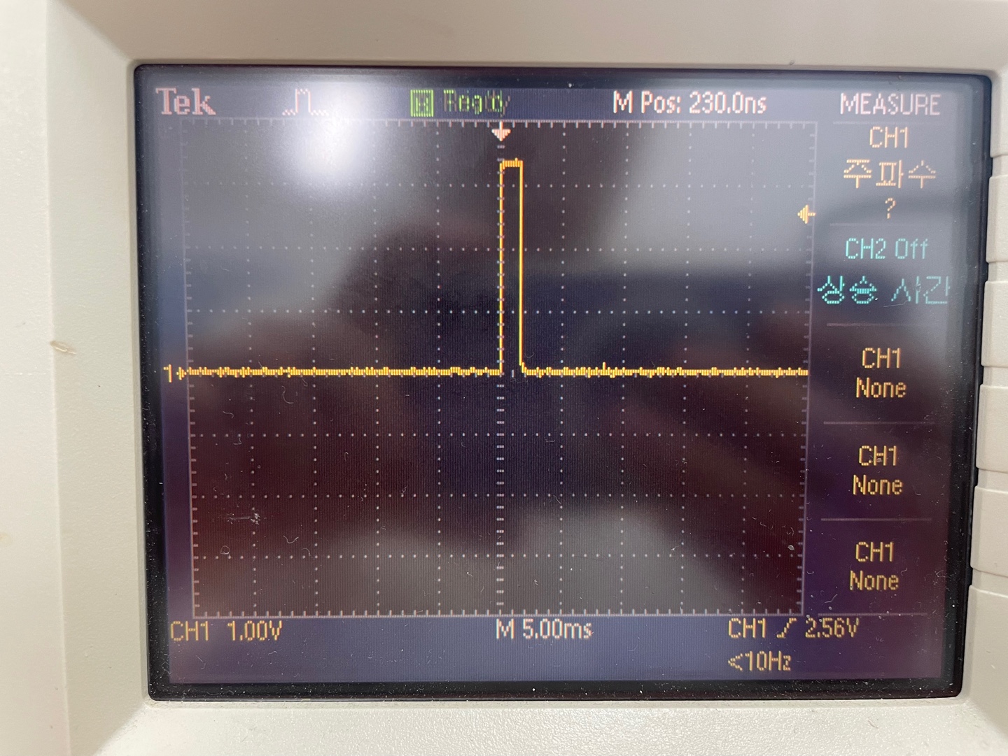
500ms 마다 인터럽트 걸고 spi signal 확인
(1) 각각의 signal check
-
LE signal (PA4, A3) -> SPI를 보내고 임의로 1ms의 펄스를 발생시킴(gpio output)
-
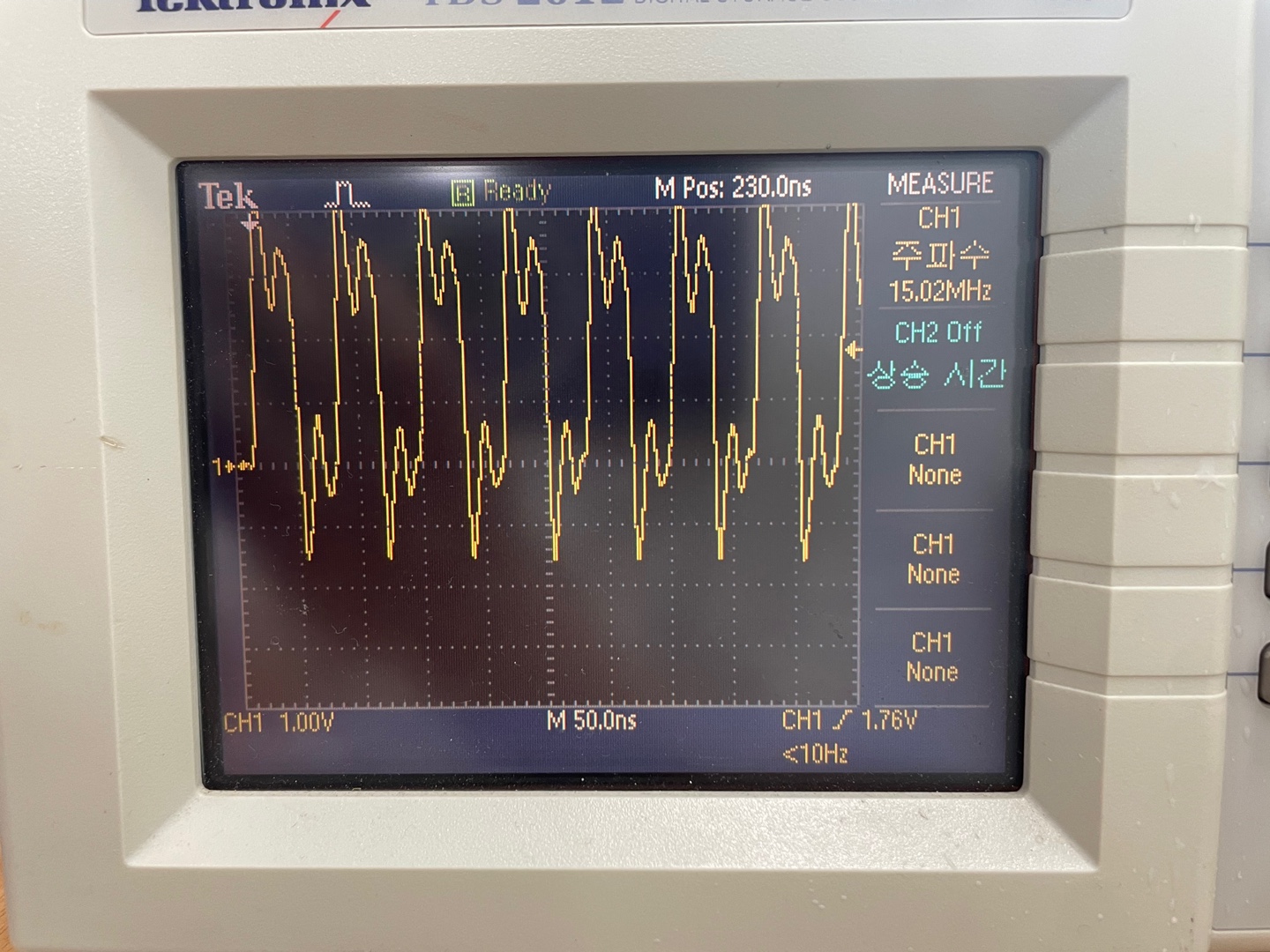
SCLK signal (PA5, A4)
-
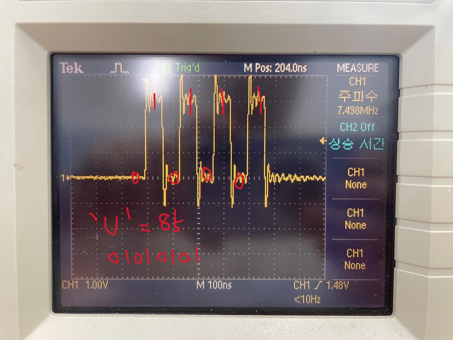
MISO signal (PA6, A5) MOSI signal (PA7, A6) Loop back Test
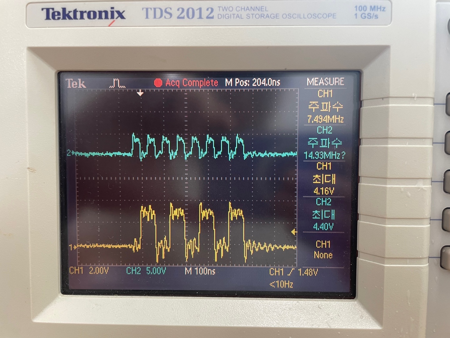
(2) signal 동시에 check
-
SCLK signal과 Loop back signal (ch1 = Loop back data, ch2 = SCLK)
-
Loop back signal과 LE신호 확인