Cortex-A series processors now include both ARMv8-A and ARMv7-A implementations:
-
The Cortex-A5,A7,A8,A9,A15,A17 processors all implement the ARMv7-A archictecture.
-
The Cortex-A53 and Cortex-A57 processors implement the ARMv8-A architecture.
The change from 32-bit to 64-bit
There are several performance gains derived from moving to a 64-bit processor.
-
The A64 instruction set provide some significant performance benefits, including a larger register pool. The additional registers and the ARM architecture Procedure Call Standard(AAPCS) provide a performance boost when you must pass more than four registers in a fuction call. On ARMv7, this would require using the stack, whereas in AArch64 up to eight parameters can be passed in registers.
-
Wider integer registers enable code that operates on 64-bit data to work more efficiently.
A 32-bit processor might require several operations to perform an arthmetic operation on 64-bit data. A 64-bit processor might be able to perform the same task in a single operation, typically at the same speed required by the same processor to perform a 32-bit operatiopn. Therefore, cdoe that performs many 64-bit sized operations is significantly faster. -
64-bit operation enables applications to use a larger virtual address space. While the Large Physical Address Extension(LPAE) extends the physical address space of a 32-bit processor to 40-bit, it does not extend the birtual address space. This means that even with LPAE, a single application is limited to a 32-bit address spae. This is because some of this addres space is reserved for the operation system.
-
Software running on a 32-bit arhitecture might need to map some data in or out of memory while executing. Having a larger address space, with 64-bit pointers, avoids this problem. However, using 64-bit points does incur some cost. The same piece of code typically uses more memory when running with 64-pointers than with 32-bit pointers.
Each pointer is stored in memory and requires eight bytes instead of four. This might sound trivial, but can add up to a significant penalty. Furthermore, the incread usage of memory space associated with a move to 64-bits can cause a drop in the number of accesses that hit in the cache. This in turn can reduce performance.
The larger virtual address space also enables memroy mapping larger files. This is the mapping of the file contents into the memory map of a thread. This can occur even though the physical RAM might not be large enough to contain the whole file.
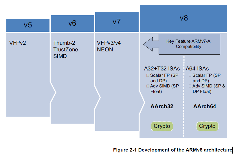
2. ARMv8-A architecture and Processor
The ARMv8-A architecture is the latest generation ARM architecture targetd at the Applications profile. The name ARMv8 is used to describe the overall architecture, which now includes both 32-bit execution with 64-bit wide registers, while perserving backwards compatibility with existing ARMv7 software.
Large physical address
This enables the processor to access beyond 4GB of physical memory.
64-bit virtual addressing
This enables virtual memory beyond the 4GB limit. This is important for modern desktop and server software using memory mapped file I/O or sparse addressing.
Automatic event signaling
This enables power-efficient,high-performance spinlocks.
Larger register files
Thirty-one 64-bit general-purpose registers increase performance and reduce stack use.
Efficient 64-bit immediate generation
There is less need for literal pools.
Large PC-relative addressing range
Large PC-relative addressing range
A +/- 4GB addressing range for efficient data addressing within shared libraries and position-independent executables.
Additional 16KB and 64KB translation granules
This redueces Translation Lookaside Buffer miss rates and depth of page walks.
New exception model
This reduees OS and hypervisor software complexity.
Efficient cache management
User space cache opertions improve dynamic code generation efficiency. Fast Data cache clear using a Data Cache Zero instruction.
Hardware-accelerated cryptography
Provides 3xto10xbetter software encryption performance. This is useful for small granule decryption and encryption too small to offload to a hardware accelerator efficiently, for example https.
Load-Acquire, Store-Release instructions
Designed for C++11, C11, Java memory medels. They improve performance of Trhead safe code by eliminating explicit memory barrier instrutions.
일반적으로, 스레드 사이에서 변수의 값을 동기화하기 위해 메모리 배리어(instructions)를 사용해야 합니다. 그러나 Load-Acquire와 Store-Release 명령어는 명시적인 메모리 배리어를 사용하지 않고도 변수 값을 동기화할 수 있는 방법을 제공합니다.

Load-Acquire (로드-획득): Load-Acquire 명령어는 변수의 값을 읽는 동작을 수행할 때, 해당 변수와 관련된 다른 메모리 액세스 연산들이 올바르게 획득되었음을 보장합니다. 이는 읽기 연산을 통해 읽은 값을 최신 상태로 유지하기 위해 사용됩니다.

Store-Release (저장-방출): Store-Release 명령어는 변수에 값을 쓰는 동작을 수행할 때, 해당 변수와 관련된 다른 메모리 액세스 연산들이 이전에 수행된 쓰기 동작과 올바르게 완료되었음을 보장합니다. 이는 쓰기 연산을 통해 쓴 값을 다른 스레드에서 정상적으로 읽을 수 있도록 보장하기 위해 사용됩니다.
NEON double precision floating point advanced SIMD This enable SIMD vectoriation to be applied to a much wider set of algorithms, for example, scientific computing, High Performance Computing and supercomputers.
ARMv8-A Processor properteis
Table 2-1 compares the properties of the processor implementations from ARM that support the ARMv8-A architecture.
Table 2-1 Comparison of ARMv8-A processors
| - | - | processor |
|---|---|---|
| - | Cortex-A53 | Cortex-A57 |
| typical clock speed | 2GHz on 28nm | 1.5 to 2.5 Ghz on 20nm |
| Cores | 1 to 4 | 1 to 4 |
| Integer Peak throughput | ||
| Floating point Unit | Yes | Yes |
| Half-precision | Yes | Yes |
| Hardware Divide | Yes | Yes |
| Fused Multiply Accumulate | Yes | Yes |
| Pipeline stages | 8 | 15+ |
| Return Stack entries | 4 | 8 |
| Generic Interrupt Controller | External | External |
| AMBA interface | 64bit | 128bit |
| L1 Cache size(instruction) | 8KB to 64KB | 48KB |
| L1 Cache structure( Instruction) | 2way set associative | 3way set associative |
| L1 Cache size(data) | 8kb to 64kb | 32KB |
| L1 Cache structure(Data) | 4way set associative | 2-way set associative |
| L2 Cache | Optional | Integrated |
| L2 Cache size | 128 KB to 2 MB | 512 KB to 2MB |
| L2 Cache structure | 16-way set associative | 16-way set associative |
| Main TLB entries | 512 | 1024 |
| uTLB entries | 10 | 48 I-sde 32 D- side |
Main TLB (Translation Lookaside Buffer) 및 uTLB (Micro TLB)는 프로세서에서 가상 메모리 주소 변환을 가속화하기 위해 사용되는 하드웨어 캐시입니다. TLB는 가상 주소와 해당하는 물리 주소 간의 매핑을 저장합니다.

당신의 질문에서 "512"와 "1024"는 Main TLB의 엔트리 수를 나타냅니다. 이는 Main TLB가 각각 512개와 1024개의 엔트리를 가지고 있다는 것을 의미합니다. Main TLB는 명령어와 데이터 모두에 대한 주소 변환을 처리하는 역할을 담당합니다.

"10"과 "48"은 I-side (명령어 쪽)의 uTLB 엔트리 수를 나타냅니다. 이는 명령어에 대한 uTLB가 각각 10개와 48개의 엔트리를 가지고 있다는 것을 의미합니다.
2.2.1 ARMv8 processors
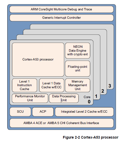
The Cortex-A53 processor
The Cortex-A53 is a mid-range, low power processor with between one and four cores in a single cluster, each with an L1 cache controller.
The Cortex-A53 processor is an extremely power efficeint processor capable of supporting 32-bit and 64 bit code. It delivers significantly higher performance than the highly successful Cortex-A7 processor. It is capale of deployment as a standalone applications procssor, or paired with the Cortex-A57 processor in a bit.LITTLE configuration for optimum performance, scalability, and energy efficiency.
ARM coreSight Multicore Debug and Trace
Generic Interrupt Controller
Cortex-A53 processor
NEON Data Engine with cryto ext
Floating point unit
Level 1 Instruction Cache
Level 1 Data Cache w/ECC
Memory management Uint
Performance Monitor Unit
Data Processing Unit
SCU
ACP
Integrated Level 2 Cache w/ECC
AMBA 4 ACE or AMBA 5 CHI Coherent Bus Interface
ARM coreSight Multicore Debug and Trace (다중 코어 디버깅 및 추적)는 ARM 프로세서 시스템에서 디버깅 및 추적 기능을 제공하는 기술입니다. 이 기술은 다중 코어 시스템에서 여러 개의 코어를 동시에 디버깅하고 각 코어의 동작을 추적하는 데 사용됩니다. coreSight는 소프트웨어 디버깅 및 성능 분석을 위한 인터페이스를 제공하여 개발자가 프로세서 시스템의 동작을 이해하고 최적화할 수 있도록 도와줍니다.

Generic Interrupt Controller (일반 인터럽트 컨트롤러)는 ARM 프로세서 시스템에서 인터럽트를 관리하는 기능을 제공하는 장치입니다. 이 컨트롤러는 다양한 소스에서 발생하는 인터럽트 신호를 처리하고 우선순위에 따라 인터럽트를 전달합니다. 이를 통해 시스템은 여러 장치 및 외부 이벤트와 효율적으로 상호작용할 수 있습니다.

Cortex-A53 프로세서는 ARM의 64비트 아키텍처인 ARMv8-A를 기반으로 한 중앙 처리 장치입니다. 이 프로세서는 저전력 및 고성능 요구 사항을 충족하기 위해 설계되었습니다. Cortex-A53는 멀티코어 구성에 적합하며, 대부분의 스마트폰, 태블릿, IoT 장치 등에서 사용됩니다.

NEON Data Engine with crypto ext (NEON 데이터 엔진 및 암호 확장)은 Cortex-A53 프로세서에 내장된 벡터 처리 기능입니다. NEON은 고성능 멀티미디어 처리, 신호 처리 및 암호화 작업에 특화된 SIMD(Single Instruction, Multiple Data) 아키텍처입니다. 암호 확장은 암호화 관련 작업을 위한 특정 명령어 세트를 제공하여 보안 작업에 더욱 최적화된 성능을 제공합니다.

Floating point unit (부동 소수점 유닛)은 실수 연산을 처리하는 하드웨어 장치입니다. Cortex-A53 프로세서는 부동 소수점 연산을 지원하기 위해 내장된 FPU(Floating Point Unit)를 가지고 있습니다. FPU는 고정 소수점 연산보다 정확도와 범위가 큰 실수 연산을 수행할 수 있습니다.

Level 1 Instruction Cache (레벨 1 명령어 캐시)는 프로세서의 내부에 위치한 캐시 메모리로, 명령어들의 실행 효율성을 높이기 위해 사용됩니다. Cortex-A53 프로세서는 내장된 L1 명령어 캐시를 가지고 있으며, 이는 프로그램의 실행 속도를 향상시키는 데 도움을 줍니다.

Level 1 Data Cache w/ECC (레벨 1 데이터 캐시 with ECC)는 프로세서의 내부에 위치한 데이터 캐시 메모리로, 데이터의 빠른 액세스와 저장을 위해 사용됩니다. ECC(Error Correction Code)는 데이터의 무결성을 보장하기 위한 오류 정정 기술로 사용되며, L1 데이터 캐시에 적용되어 데이터의 신뢰성을 높입니다.

Memory Management Unit (메모리 관리 유닛)은 프로세서가 가상 주소를 실제 물리 주소로 변환하고 메모리 액세스를 관리하는 하드웨어 장치입니다. MMU는 가상 메모리 시스템을 지원하여 프로세스 간 메모리 보호, 가상 메모리 관리, 페이지 교체 등을 가능하게 합니다.

Performance Monitor Unit (성능 모니터 유닛)는 프로세서의 동작을 모니터링하고 성능 분석을 위한 통계 데이터를 수집하는 장치입니다. PMU는 프로세서의 작동 주기, 명령어 실행, 캐시 액세스 등 다양한 성능 정보를 제공하여 시스템 최적화 및 디버깅에 활용됩니다.

Data Processing Unit (데이터 처리 유닛)는 프로세서 내에서 데이터 연산을 수행하는 부분입니다. Cortex-A53 프로세서는 내장된 DPU(Data Processing Unit)를 가지고 있으며, 이는 다양한 산술 연산과 논리 연산을 지원하여 데이터 처리 작업을 가속화합니다.

SCU (Snoop Control Unit)는 멀티코어 시스템에서 캐시 일관성을 관리하는 장치입니다. SCU는 캐시 간 데이터 일관성을 유지하여 다중 코어가 동시에 액세스하는 메모리에 대한 일관성을 제공합니다.

ACP (Accelerator Coherency Port)는 가속기와 프로세서 사이의 데이터 일관성을 유지하는 인터페이스입니다. ACP는 가속기가 메모리와 상호작용할 때 캐시 일관성을 보장하여 데이터 일관성 오류를 방지합니다.

Integrated Level 2 Cache w/ECC (통합 레벨 2 캐시 with ECC)는 프로세서 내에 내장된 레벨 2 캐시 메모리로, 높은 용량의 데이터를 저장하고 액세스할 수 있습니다. ECC는 L2 캐시에도 적용되어 데이터의 무결성을 보호합니다.

AMBA 4 ACE 또는 AMBA 5 CHI Coherent Bus Interface (AMBA 4 ACE 또는 AMBA 5 CHI 일관성 버스 인터페이스)는 ARM 프로세서와 다른 시스템 컴포넌트 간에 통신을 위한 버스 프로토콜입니다. 이 인터페이스는 데이터와 명령어의 일관성을 유지하고 효율적인 데이터 전송을 지원하여 시스템 전체의 성능을 향상시킵니다.
The Cortex-A53 processor has the following features :
- In-order, eight stage pipeline
- Low power consumption from the use of hierarchical clock gating, power domains, and advanced retention modes.
- Increased dual issue capability from duplication of execution resources and dual instruction decoders.
- Power optimized L2 cache design delivers lower latency and balances performance with efficiency.
The Cortex-A57 processor
The Cortex-A57 processor is targeted at mobile and enterprise computing applications including compute intensive 64 bit applications such as high end computer, tablet, and server products. It can be used with the Cortex-A53 processor into an ARM big.LITTLE configuration, for scalable performance and more efficient energy use.
The Cortex-A57 processor features cache coherent interoperability with other processors, including the ARM Mali family of Graphics Processing Units(GPUs) for GPU comput and provides optional reliability and scalability features for high performance enterprise applications. It provides significantly more performance than the ARMv7 Cortex-A15, at a higher level of power efficiency. The inclusion of cryptography extensions improves performance on cryptography algorithms by 10 times over the previous generation of processors.
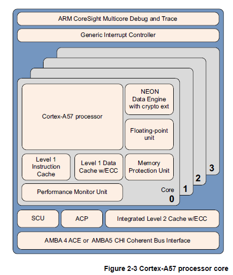
The Cortex-A57 processor fully implements the ARMv8-A architecture. It enalbes multi core operation with between one and four cores multi processing within a single cluseter. Multiple coherent SMP clusters are possible, through AMBA5 CHI or AMBA 4 ACE technology. Debug and trace are acailable throught CoreSight technology.
The Cortex-A57 processor has the following features :
-
Out of order, 15+stage pipe line.
-
Power saving features include way-prediction, tag reduction and cache-lookup suppression.
-
Increased peak instruction throughput through duplication of execution resources Power optimized instruction throughtput through duplication of execution resources.
Power optimized instruction decode with localized decoding, 3 wide decode bandwith. -
Performance optimized L2 cache design enables more than one core in the cluster to access the L2 at the same time.
Cortex-A57 프로세서는 ARM의 64비트 아키텍처인 ARMv8-A를 완전히 구현한 중앙 처리 장치입니다. 이 프로세서는 고성능 및 에너지 효율성을 제공하기 위해 설계되었습니다.

Cortex-A57는 멀티코어 운영을 지원합니다. 하나의 클러스터 내에서 1개에서 4개의 코어를 가질 수 있으며, 각 코어는 독립적으로 작업할 수 있습니다. 이를 통해 병렬 처리를 통해 작업 성능을 향상시킬 수 있습니다. 또한, AMBA5 CHI 또는 AMBA 4 ACE 기술을 사용하여 여러 개의 클러스터를 연결하여 일관성을 유지하고 다중 클러스터 SMP(System on a Chip) 구성을 구현할 수 있습니다.

Cortex-A57 프로세서는 CoreSight 기술을 사용하여 디버깅 및 추적 기능을 제공합니다. 이를 통해 개발자는 프로세서 동작을 분석하고 문제를 해결할 수 있습니다.

프로세서의 내부에는 다음과 같은 주요 기능이 있습니다:

Out-of-order, 15+ stage pipeline: 프로세서는 명령어들을 순서대로 처리하지 않고, 데이터 종속성을 고려하여 최적의 실행 순서를 결정합니다. 이를 통해 명령어 실행 효율을 극대화할 수 있습니다. 파이프라인은 15개 이상의 단계로 구성되어 있습니다.

Power-saving features: 프로세서는 웨이 예측(way-prediction), 태그 감소(tag-reduction), 캐시 조회 억제(cache-lookup suppression)와 같은 저전력 기능을 갖추고 있습니다. 이러한 기능은 전력 소비를 줄이고 에너지 효율성을 향상시킵니다.

Increased peak instruction throughput: 실행 리소스를 복제함으로써 명령어 처리량을 증가시킵니다. 이는 동시에 여러 명령어를 실행하여 작업 성능을 향상시키는 데 도움이 됩니다. 프로세서는 전력 최적화된 명령어 디코드를 갖추고 있어 명령어 해석 속도를 높이는데 기여합니다.

Performance optimized L2 cache design: 프로세서는 L2 캐시 설계를 최적화하여 클러스터 내의 여러 코어가 동시에 L2 캐시에 액세스할 수 있습니다. 이는 데이터 공유 및 일관성 유지를 용이하게 하며, 작업 성능을 향상시킵니다. 또한, L2 캐시에는 ECC(Error Correction Code)가 적용되어 데이터의 신뢰성을 높입니다.

이러한 기능들은 Cortex-A57 프로세서를 효율적이고 고성능인 프로세싱 솔루션으로 만들어 줍니다.
Level 1 Instruction Cache (레벨 1 명령어 캐시)는 프로세서의 내부에 위치한 캐시 메모리로, 명령어들을 저장하고 실행 효율성을 높이기 위해 사용됩니다. 일반적으로 L1 Instruction Cache에는 ECC (Error Correction Code) 기능이 적용되지 않습니다.
ECC는 데이터의 무결성을 보호하기 위해 사용되는 오류 정정 기술로, 데이터 캐시에 적용되는 경우 주로 사용됩니다. 데이터 캐시는 프로그램에서 읽고 쓰는 데이터를 임시로 저장하는 용도로 사용되기 때문에 데이터의 신뢰성이 중요합니다. 따라서 데이터 캐시에는 ECC 기능이 포함되어 데이터 오류를 감지하고 복구할 수 있습니다.
반면, 명령어 캐시는 프로세서가 명령어를 가져와 실행하는 데 사용되는데, 명령어 자체가 변하지 않고 정적으로 유지되기 때문에 일반적으로 ECC 기능이 적용되지 않습니다. 명령어 캐시의 주된 목적은 명령어를 빠르게 액세스하여 프로세서의 실행 성능을 향상시키는 것입니다.
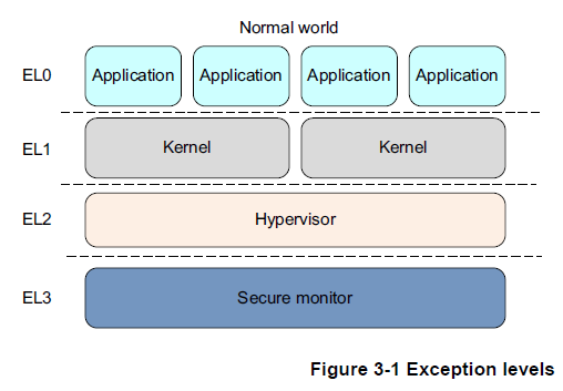
따라서, Level 1 Instruction Cache에 ECC 기능이 없는 것은 일반적인 설계 선택이며, 명령어의 무결성을 보장하기 위해 다른 방법이 사용될 수 있습니다.In ARMv8, execution occurs at one of four Exception levels. In AArch64, the Exception level determines the level of privilege, in a similar way to the privilege levels defined in ARMv7.
The Exception level determines the privilege level, so execution at ELn corresponds to privilege PLm. Similarly, an Exception level with a larger value of n than another one is at a higher Exception level. An Exception level with a smaller number than another is described as being at a lower Exception level.
Exception levels provide a logical separation of software execution privilege that applies across all operating states of the ARMv8 architecture. It is similar to, and supports the concept of, hierarchical protection domains common in computer science.
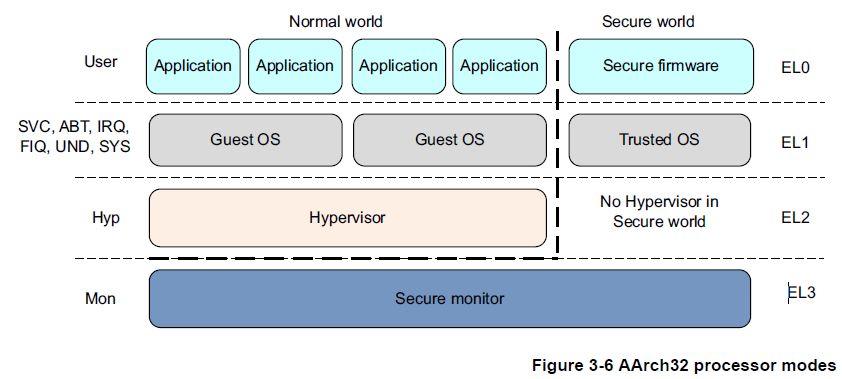
The following is a typical example of what software runs at each Exception level :
EL0 Normal user application
EL1 Operatig System Kernel typically described as privileged.
EL2 Hypervisor.
EL3 Low-level firmware, including the Secure Monitor.
In general, a piece of software, such as an application, the kernel of an operating system, or a hypervisor, occupies a single Exception level, An exception to this rule is in-kernel hypervisors such as KVM, which operate across both EL2 and EL1.
ARMv8-A provides two security states, Secure and Non-secure. The Non-secure state is also referred to as the Normal World. This enables an Operating System(OS) to run in parallel with a trusted OS on the same hardware, and provides protection against certain software attacks and hardware attacks. AMR TrustZone technology enables the system to be partitioned between the Normal and Secure worlds. As with the ARMv7-A architecture, the Secure monitor acts as a gateway for moving between the Normal and Secure worlds.
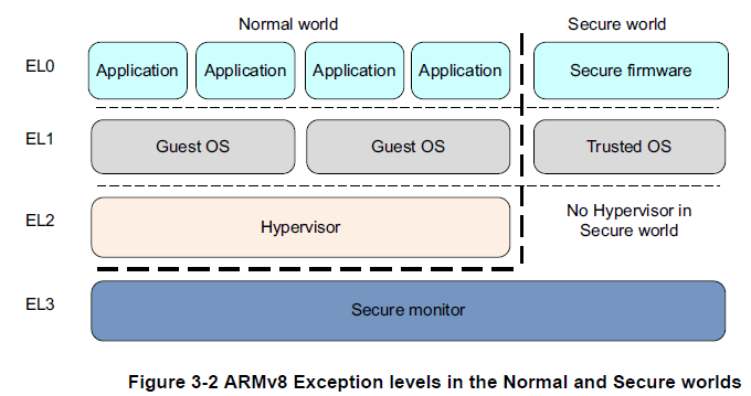
ARMv8-A also provides support for virtualization, though only in the Normal world. This means that hypervisor, or Virtual Machine Manager(VMM) code can run on the system and host multiple guest operatin systems. Each of the guest operating system is, essentially, running on a virtual machine. Each OS is ten unaware that it is sharing time on the system with other guest opertaing systems.
The Normal world (which corresponds the Non-secure state) has the following privileged components :
Guest OS kernels
Such kernels include linux or windows unnning in Non-secure EL1. When running uner a hypervisor, the rich OS kernels can be running as a guest or host depending on the hypervisor model.
Hypervisor
This runs at EL2, which is always Non-secure. The hypervisor, when present and enabled, provides virtualization services to rich OS kernels.
The Secure world has the following privileged componets :
Secure firmware
On an application processor, this firmware nust be the first thing that runs at boot time. It provides several services, including platform initialization, the installation of the trusted OS, and routing of Secure monitor calls.
Trusted OS
Trusted OS provides Secure services to the Normal world and provides a runtime enviroment for executin Secure or trusted applications.
The Secure monitor in the ARMv8 architecture is at a higher Exception level and is more privileged than all other levles. This provides logical model of software privilege.
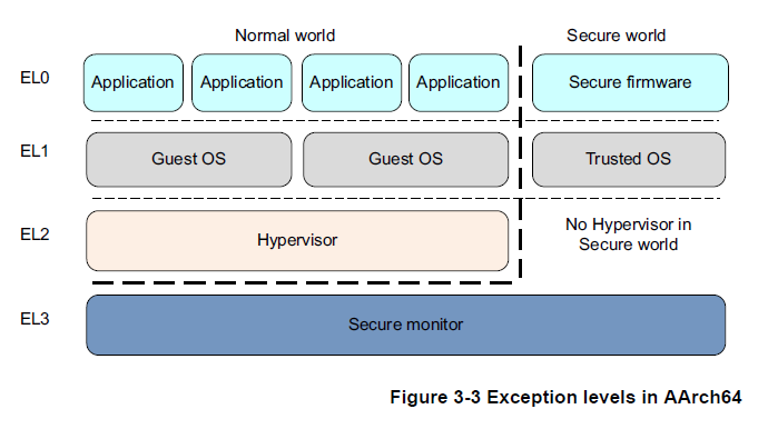
3.1 Execution states
The ARMv8 architecture defines two execution States, AArch64 and AArch32. Each state is used to describe execution using 64-bit wide general purpose registers or 32-bit wide general purpose registers, respectively. While ARMv8 AArch32 retains the ARMv7 definitions of privilege, in AArch64, privilege level is determined by the Exception level. Therefore, execution at ELn corresponds to privilege PLn.
When in AArch64 state, the processor executes the A64 instruction set. When in AArch32 state, the processor can execute either the A32(called ARM in earlier versions of the architecture) or the T32 (Thumb) instruction set.
The following diagrams show the organization of the Exception levels in AArch64 and AArch32.
In AArch64 :
In AArch32 :
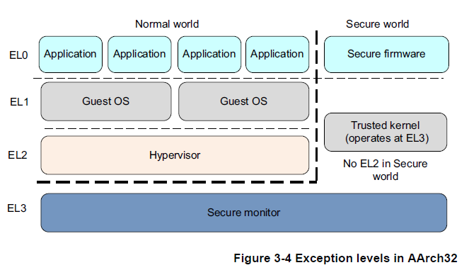
In AArch32 state , Trusted OS software executes in Secure EL3, and in AArch64 state it primarily executes in Secure EL1.
3.2 Changing Exception levels
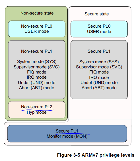
In the ARMv7 architecture, the processor mode can change under privileged software control or automatically when taking an exception. When an exception occurs, the core saves the currnet execution state and return addres, enters the requried mode, and possibly diables hardware interrupts.
This is summarized in the following table. Applications operate at the lowest level of privilege, PL0, previously unprivileged mode. Operating systems runs at PL1, and the Hypervisor in a system with the Virtualization extensions at PL2. The Secure monitor, which acts as a gateway for moving between the Secure and Non secure worlds, also poerates at PL1.
ARMv7 아키텍처에서는 프로세서 모드가 권한 있는 소프트웨어 제어 또는 예외 발생 시 자동으로 변경될 수 있습니다. 예외가 발생하면 코어는 현재 실행 상태와 반환 주소를 저장하고 필요한 모드로 진입하며, 하드웨어 인터럽트를 비활성화할 수도 있습니다.

이는 다음 표에 요약되어 있습니다. 응용 프로그램은 가장 낮은 권한 수준인 PL0(이전에 비권한 모드)에서 동작합니다. 운영 체제는 PL1에서 실행되고, 가상화 확장을 갖춘 시스템에서는 Hypervisor가 PL2에서 실행됩니다. Secure monitor는 Secure 및 Non-secure(일반) 월드 간 이동을 위한 게이트웨이로 작동하며, 이 또한 PL1에서 동작합니다.
Table 3-1 ARMv7 processor modes
| 모드 | 기능 | 보안 상태 | 권한 수준 |
|---|---|---|---|
| User (USR) | 대부분의 응용 프로그램이 실행되는 비권한 모드 | 양상태 (Both) | PL0 |
| FIQ | FIQ 인터럽트 예외가 발생할 때 진입하는 모드 | 양상태 (Both) | PL1 |
| IRQ | IRQ 인터럽트 예외가 발생할 때 진입하는 모드 | 양상태 (Both) | PL1 |
| Supervisor | 리셋시 또는 Supervisor Call 명령어 (SVC) 실행시 진입하는 모드 | 양상태 (Both) | PL1 |
| Monitor | SMC 명령어 (Secure Monitor Call) 실행시 또는 프로세서가 안전한 처리를 위해 예외를 수행할 때 진입하는 모드 | 안전한 상태 (Secure) | PL1 |
| Abort | 메모리 접근 예외가 발생할 때 진입하는 모드 | 양상태 (Both) | PL1 |
| Undef | 정의되지 않은 명령어가 실행될 때 진입하는 모드 | 양상태 (Both) | PL1 |
| System | 사용자 모드와 레지스터 뷰를 공유하는 권한 있는 모드 | 양상태 (Both) | PL1 |
| Hyp | Hypervisor Call 및 Hyp Trap 예외로 진입하는 모드 | 비안전한 상태 (Non-secure) | PL2 |
Movement between Exception levels follows these rules :
-
Moves to a higher Exception level, such as from EL0 to EL1, indicate increased software execution privilege.
-
An exception cannot be taken to a lower Exception level.
-
There is no exception handling at level EL0, exceptions must be handled at a higher Exception level.
-
An exception causes a change of program flow. Execution of an exception handler starts, at an Exception level higher than EL0, from a defined vector that relates to the exception taken, Exceptions include:
-
Interrupts such as IRQ and FIQ.
-
Memory system aborts.
-
Undefined instructions.
-
System calls. These permit unprivileged software to make a system call to an operating system.
-
Secure monitor or hypervisor traps.
-
Ending exception handling and returning to the previous Exception level is performed by executing the ERET instruction.
-
Returning from an exception can stay at the same Exception level or enter a lower Exception level. It cannot move to a higher Exception level.
-
The security state does change with a change of Exception level, except when returning from EL3 to a Non-secure state.
IRQ 및 FIQ와 같은 인터럽트
메모리 시스템의 중단
정의되지 않은 명령어
시스템 호출. 이는 비권한 소프트웨어가 운영 체제에 시스템 호출을 할 수 있도록 허용합니다.
안전한 모니터 또는 하이퍼바이저 트랩
• 예외 처리의 종료 및 이전 예외 레벨로의 복귀는 ERET 명령어를 실행하여 수행됩니다.
• 예외에서의 복귀는 동일한 예외 레벨에 머무를 수도 있고, 더 낮은 예외 레벨로 진입할 수도 있습니다. 그러나 더 높은 예외 레벨로 이동할 수는 없습니다.
• 예외 레벨의 변경으로 인해 보안 상태가 변경됩니다. 다만, EL3에서 비안전한 상태로 복귀할 때는 보안 상태가 변경되지 않습니다
3.3 Changing execution state
There are times when you must change the execution state of your system. This could be, for example, if you are running a 64 bit operating system, and want to run a 32-bit application at EL0. To do this, the system must change to AArch32.
When the application has completed or execution returns to the OS, the system can switch back to AArch64.
To change between execution states at the same Exception level, you have to switch to a higher EXception level then return to the origianl Exception levle. For example, you migh have 32-bit and 64-bit applications running under a 64-bit OS. In this case, the 32-bit application can execute and generate a Supervisor Call instruction, or receive an interrupt, causing a switch to EL1 and AArc64. The OS can than do a task switch and return to EL0 in AArch64. Practivally speaking, this means that you cannot have a mixed 32-bit and 64-bit application, because there is no direct way of calling between them.
You can only change execution state by changing Exception level. Taking an exception might change from AArc32 to AArch64, and returning from an exception may change from AArch64 to AArch32.
Code at EL3 cannot take an exception to a higher exception level, so cannot change execution state, except by going through a reset.
The follwing is a summary of some of the points when changing between AArch64 and AArch32 execution states :
-
Both AArch64 and AArch32 execution states have Exception levels that are generally similar, but there are some differences between Secure and Non secure operation. The execution state the processor is in when the exception is genreated can limit the Exception levels available to the other execution state.
-
Changing to AArch32 requires going from a higher to a lower Exception level. This is the result of exiting an exception handler by executing the ERET instruction. See Exception handling instructions on page 6-21.
-
Changing to AArc64 requires going from to lower to a higher Exception level. The exception can be the result of an insturciton execution or an external signal.
-
If, when taking an exception or returning from an exception, the Exception level remains the same, the execution state cannot change.
-
where an ARMv8 processor oprates in AArch32 execution state at a particular Excpetion level. it uses the same exception modeal as in Armv7 for exceptions taken to taht Exception level. In the AArch64 execution state, it uses the exception hgandling model described in Cahpter 10
시스템의 실행 상태를 변경해야 하는 경우가 있습니다. 예를 들어, 64비트 운영 체제에서 32비트 응용 프로그램을 EL0에서 실행하고자 할 때는 시스템을 AArch32로 변경해야 합니다.
동일한 예외 수준에서 실행 상태를 변경하려면 더 높은 예외 수준로 전환한 다음 원래의 예외 수준으로 돌아와야 합니다.
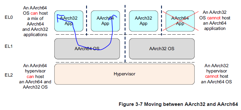
예를 들어, 64비트 운영 체제에서 32비트와 64비트 응용 프로그램을 실행할 수 있습니다. 이 경우 32비트 응용 프로그램은 감독 호출(SVC) 명령을 실행하거나 인터럽트를 받아 EL1과 AArch64로 전환될 수 있습니다. (페이지 6-21의 예외 처리 명령을 참조하십시오.) 그런 다음 운영 체제는 작업 전환을 수행하고 AArch64에서 EL0로 돌아갈 수 있습니다.Interworking between the two states is therefore performed at the level of the Secure monitor, hypervisor or operating system. A hypervisor or operating system executing in AArch64 state can support AArch32 operation at lower privilege levels. This means that an OS running in AArch64 can host both AArch32 and AAarch64 applications. Similarly, an AArch64 hypervisor can host both AArch32 and AArch64 guest operating systems. However, a 32-bit operating system cannot host a 64-bit application and a 32-bit hypervisor cannot host a 64-bit guest operating system.
Chapter 4 ARMv8 Registers
The AArch64 execution state provides 31X64bit general purpose registers accessible at all times and in all Exception levels.
Each register is 64 bits wide and they are generally referred to as register X0-X30.
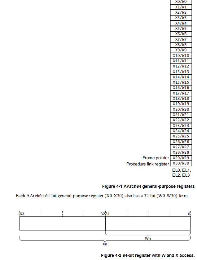
Reads from W registers disregard the higher 32 bits of the correspondding X register and leave them unchanged. Writes to W registers set the higher 32 bits of the X register to zero. That is, writing 0xFFFFFFFF into W0 sets X0 to 0x00000000FFFFFFFF
AArch64 special registers
In addition to the 31 core registers, there are also several special registers
Zero register
Program Counter
Stack pointer
Program Status Register
Exception Link Register
Zero register (제로 레지스터): 제로 레지스터는 ARM 프로세서에서 항상 0 값을 가지는 특수한 레지스터입니다. 주로 연산 결과가 0인 경우에 사용되며, 논리 연산이나 조건 분기와 같은 명령에서 활용될 수 있습니다.

Program Counter (프로그램 카운터): 프로그램 카운터는 ARM 프로세서에서 다음에 실행될 명령어의 주소를 저장하는 레지스터입니다. 명령어의 실행이 진행될 때마다 프로그램 카운터는 자동적으로 증가하여 다음 명령어의 주소를 가리킵니다.

Stack pointer (스택 포인터): 스택 포인터는 스택 영역에서 현재 스택의 최상단을 가리키는 주소를 저장하는 레지스터입니다. 스택은 함수 호출과 반환, 지역 변수의 저장 등에 사용되며, 스택 포인터는 스택에 데이터를 푸시(push)하거나 팝(pop)할 때 사용됩니다.

Program Status Register (프로그램 상태 레지스터): 프로그램 상태 레지스터는 ARM 프로세서에서 다양한 상태 정보를 저장하는 레지스터입니다. 예를 들어, 조건 코드, 상태 플래그, 인터럽트 비트 등의 정보를 저장합니다. 프로그램 상태 레지스터는 프로세서의 동작 제어와 상태 관리에 사용됩니다.

Exception Link Register (예외 링크 레지스터): 예외 링크 레지스터는 ARM 프로세서에서 예외 처리 중에 이전 실행 상태를 저장하는 레지스터입니다. 예외가 발생하면 프로그램 카운터의 값이 예외 링크 레지스터에 저장되어 이전의 실행 위치를 기억합니다. 이후 예외 처리가 완료되면 예외 링크 레지스터의 값으로 복귀하여 예외 이전 상태로 돌아갈 수 있습니다.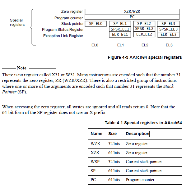
예시를 들어 설명드리겠습니다.

예를 들어, 아래의 명령어는 숫자 31을 제로 레지스터(ZR)로 인코딩하여 사용합니다:

scss
Copy code
ADD X0, X1, XZR   ; X0 = X1 + 0 (ZR)
SUB W2, W3, WZR  ; W2 = W3 - 0 (ZR)
위의 예시에서 XZR은 64비트 제로 레지스터(X31에 해당)를 나타내며, WZR은 32비트 제로 레지스터(W31에 해당)를 나타냅니다. 숫자 31은 제로 레지스터로 사용되어 해당 레지스터에 0 값을 의미합니다.

또한, 스택 포인터(SP)를 나타내기 위해 숫자 31이 인수로 사용되는 예시를 살펴보겠습니다:

bash
Copy code
LDR X0, [SP, #31]  ; X0 = SP + 31
위의 예시에서는 SP에 31을 더한 값을 X0에 로드합니다. 여기서 숫자 31은 SP(스택 포인터)를 나타내며, 현재 스택의 위치를 가리킵니다.

이러한 방식으로 명령어가 인코딩되어 숫자 31이 제로 레지스터 또는 스택 포인터를 나타내는데 사용됩니다.
In the ARMv8 architecture, when executing in AArch64, the exception return state is held in the following dedicated registers for each Exception level :
- Exception Link Register(ELR).
- Saved Processor State Register(SPSR).
ARMv8 아키텍처에서 AArch64로 실행될 때, 예외 복귀 상태는 각 예외 수준에 대해 다음과 같은 전용 레지스터에 저장됩니다:

예외 링크 레지스터 (ELR): 예외 링크 레지스터는 각 예외 수준마다 예외 복귀 주소를 저장하는 데 사용됩니다. 예외가 발생할 때 현재 명령어의 주소가 ELR에 저장되며, 예외 처리가 완료되면 해당 주소로 복귀합니다.

저장된 프로세서 상태 레지스터 (SPSR): SPSR은 각 예외 수준에 대해 예외가 발생하기 전의 프로세서 상태를 저장하는 데 사용됩니다. 예외가 발생하면 현재의 프로세서 상태 (플래그, 모드, 인터럽트 비트 등)가 SPSR에 저장되며, 예외 처리가 완료된 후 이전 상태로 복귀할 때 사용됩니다.
There is a dedicated SP per Exception level, but it is not used to hold return state.
zero register
The zero register reads as zero when used as a source register and discards the result when used as a destination register. You can use the zero reigster in most, but not all , instructions.
stack pointer
In the ARMv8 architecture, the choice of stack pointer to use is separated to some extent from the Exception level. By default, taking an exception selects the stack pointer for the target Exception level, SP_ELn. for example, tacking an exception to EL1 selects SP_EL1.''When in AArch64 at an Exception level other than EL0, the processor can use either :
-
A dedicated 64bit stack pointer associated with that Exception level(SP_ELn).
-
The stack pointer ssociated with EL0(SP_EL0).
EL0 can only ever access SP_EL0
The t suffix indicates that the SP_EL0 stakc pointer is selected. The h suffix indicates that the SP_ELn stack pointer is selected.
The SP cannot be referenced by most instructions. However, some forms of arithmetic instructions, for example, the ADD instruciton, can read and write to the currnet stack pointer to adjust the stack pointer in a unctiopn.
->
ARMv8 아키텍처에서는 대부분의 명령어에서 스택 포인터(SP)를 직접 참조할 수 없습니다. 그러나 ADD와 같은 일부 산술 명령어는 현재 스택 포인터의 값을 읽고 쓸 수 있어 스택 포인터를 조정하는 데 사용될 수 있습니다.

예를 들어, ADD SP, SP, #0x10은 함수 내에서 스택 포인터를 조정하는 방법을 보여줍니다. 이 명령은 스택 포인터의 현재 값에 0x10이라는 즉시값을 더하고 그 결과를 다시 스택 포인터에 저장합니다. 이로써 스택 포인터는 0x10바이트만큼 증가하여 스택에 추가적인 공간을 할당하게 됩니다.
4.1.3 Program Counter
One feature of the original ARMv7 instruction set was the use of R15, the Program Counter as a general purpose register. The PC enabled some clever programming tricks, but it introduced complications for compilers and the design of complex pipelines. Removing direct access to the PC in ARMv8 makes return prediction easier and simplifies the ABI specification.
The PC is never accessible as a named register. Its use is implicit in certain instuctions such as PC-relative load and address generation. The PC cannot be specified as the destination of a data processing insturcion or load instruction.
4.1.4 Exception Link Register (ELR)
The Exception Link Register holds the exception return address.
4.1.5 Saved Processs Status Register
When taking an exception, the processor state is stored in the relevant Saved Program Status Register(SPSR), in a similar way to the CPSR in ARMv7. the SPSR holds the value of PSTATE before taking an exception and is used to restore the value of PS
| 31 | 30 | 29 | 28 | 27 26 25 24 23 22 | 21 | 20 | 19 18 17 16 15 14 13 12 11 10 | 9 | 8 | 7 | 6 | 5 | 4 | 3 2 1 0 |
|---|---|---|---|---|---|---|---|---|---|---|---|---|---|---|
| N | Z | C | V | SS | IL | D | A | I | F | M | M[3:0] |
The individual bits represent the following values for AArch64 :
N Negative result (N flag )
Z Zero Result (z) flag
C Carry out(C flag).
V Overflow (V flag).
SS Software Steop. Indicate whether software step was enabled when an exception was taken.
IL Illegal Execution State bit. Shows the value of PSTATE.IL immediately before the exception was take.
D Process state Debug mask. Indicates whether debug exceptions from watchpoint, breakpoint, and software step debug events that are targeted at the Exception level the exception occurred in were masked or not.
A SError(System Error)mask bit.
I IRQ mask bit.
F FIQ mask bit.
M[4] Execution state that the exception was taken from . A value of 0 indicates AArch 64.
M[3:0] Mode of Exception level that an exception was taken from.
In ARMv8, the SPSR written to depends on the Exception level. If the exception is taken in EL1, then SPSR_EL1 is used.
AArch64에서의 PSTATE(Program Status Register)의 각 비트는 다음과 같은 의미를 가지고 있습니다.

N (Negative): 이 비트는 연산 결과가 음수일 때 N 플래그로 설정됩니다. 예를 들어, 연산 결과가 음수이면 N=1이 되고, 양수나 0인 경우 N=0이 됩니다.

Z (Zero): 연산 결과가 0일 때 Z 플래그로 설정됩니다. 연산 결과가 0이면 Z=1이 되고, 0이 아닌 경우 Z=0이 됩니다.

C (Carry): 이 비트는 캐리 아웃(Carry out)이 발생했을 때 C 플래그로 설정됩니다. 예를 들어, 덧셈에서 발생한 캐리 아웃이나 뺄셈에서 발생한 캐리인(Carry-in)을 나타냅니다.

V (Overflow): 오버플로우(Overflow)가 발생했을 때 V 플래그로 설정됩니다. 예를 들어, 부호 있는 정수 연산에서 범위를 넘어가는 오버플로우가 발생하면 V=1이 되고, 그렇지 않은 경우 V=0이 됩니다.

SS (Software Step): 소프트웨어 스텝이 활성화되어 예외가 발생했을 때 SS 비트가 설정됩니다. 소프트웨어 스텝은 디버깅 도구를 사용하여 프로그램을 단계별로 실행할 때 사용되는 기능입니다.

IL (Illegal Execution State): 예외가 발생하기 직전의 PSTATE.IL 값을 나타냅니다. PSTATE.IL은 비정상적인 실행 상태를 나타내는 비트입니다.

D (Process state Debug mask): 디버그 마스크로, 디버그 예외가 예외가 발생한 예외 수준에서 마스크되었는지 여부를 나타냅니다.

A (SError mask): 시스템 오류(SError) 마스크로, SError 예외가 마스크되었는지 여부를 나타냅니다.

I (IRQ mask): 인터럽트(IRQ) 마스크로, IRQ가 마스크되었는지 여부를 나타냅니다.

F (FIQ mask): 고속 인터럽트(FIQ) 마스크로, FIQ가 마스크되었는지 여부를 나타냅니다.

M[4] (Execution state): 예외가 발생한 실행 상태를 나타냅니다. AArch64에서는 M[4] 비트의 값이 0이면 AArch64 실행 상태임을 나타냅니다.

M[3:0] (Mode or Exception level): 예외가 발생한 모드 또는 예외 수준을 나타냅니다. 예를 들어, 0b1001은 EL1 (Exception Level 1)을 나타냅니다. 다양한 모드와 예외 수준에는 고유한 값을 가지게 됩니다.
4.2 Processor state
AArch64 does not have a direct equivalent of the ARMv7 Current Program Satus Register(CPSR). In AArch64, the components of the traditional CPSR are supplied as fields that can be made accessible independently. These are referred to collectively as Processor State(PSTATE).
The Processor State, or PSTATE fields, for AArch64 have the following definitions :
Table 4-4 PSTATE field definitions
| Name | Desrciption |
|---|---|
| N | Negative condition flag |
| Z | Zero condition flag. |
| C | Carry condition flag. |
| V | overflow condition flag. |
| D | Debug mask bit. |
| A | SError mask bit. |
| I | IRQ mask bit. |
| F | FIQ mask bit. |
| SS | Software Steop bit. |
| IL | Illegal execution state bit |
| EL(2) | Excetion level. |
| nRW | Execution state 0 = 64-bit 1 = 32-bit |
| SP | Stack ponter selector 0 = SP_EL0, 1 = SP_ELn |
In AArch64, you return from an exception by executing the ERET instruction, and this causes the SPSR_ELn to be copied into PSTATE. This restores the ALU flags, execution state, Exception level, and the processor branches. From here , you continue execution from the address in ELR_ELn.
The PSTATE, {N, Z, C, V} fields can be accessed at EL0. All other PSTATE fields can be executed at EL1 or higher and are UNDEFINED at EL0.
AArch64 아키텍처에서는 ARMv7의 CPSR(Current Program Status Register)와 직접적인 동등한 레지스터가 없습니다. AArch64에서는 전통적인 CPSR의 구성 요소들이 개별적으로 접근할 수 있는 필드로 제공됩니다. 이들은 모두 통칭해서 프로세서 상태(PSTATE)라고 합니다.

AArch64에서는 ERET 명령을 실행하여 예외에서 복귀합니다. 이로 인해 SPSR_ELn이 PSTATE로 복사되며, 이는 ALU 플래그, 실행 상태, 예외 수준 및 프로세서 분기 등을 복원합니다. 여기에서 ELR_ELn의 주소에서 실행을 계속합니다.

PSTATE의 {N, Z, C, V} 필드는 EL0에서 접근할 수 있습니다
4.3 System registers
In AArch64, system configuration is controlled through system registers, and accessed using MSR and MRS instrucitons. This contrast with ARMv7-A, where such registers were typically accessed through coprocessor 15(CP15) operations. The name of a register tells you the lowest Exception level that it can be accessed from.
For example :
- TTBR0_EL1 is accessible from EL1, EL2, and EL3.
- TTBR0_EL2 is accessible from EL2, and EL3.
REgisters that have the suffix _ELn have a separate,banked copy in some or all of the levels though usualy not EL0. Few system registers are accessible from EL0, although the Cache Type Register(CTR_EL0) is an example of one that can be accessuble.
Code to access system registers takes the following form :
MRS x0, TTBR0_EL1
MSR TTBRO_EL1, x0
AArch64 아키텍처에서는 시스템 구성이 시스템 레지스터(system registers)를 통해 제어되며, MSR 및 MRS 명령을 사용하여 액세스됩니다.
The table shows the Exception levels taht have separate copies of each register. For example, separate Auxiliary Control Registers(ACTLRs) exist as ACTLR_EL1, ACTLR_EL2 and ACTLR_EL3.
Table 4-5 System registers
| Name | Register | Description | Allowed Values of n |
|---|---|---|---|
| ACTLR_ELn | Auxiliary Control Register | Controls processor-specific features. | 1,2,3 |
| CCSIDR_ELn | Current Cache Size ID Register | Provides information about the architecture of the currnetly selected cache. | 1 |
| CLIDR_ELn | Cache Level ID Regsiter | The type of chache, or chches, implemented at each level. The level of Coherency and level of Unification for the cache hierarchy. | 1,2,3 |
| CNTFRQ_ELn | Counter-timer Requecny Register | Reports the Frequency of the System timer. | |
| CNTPCT_ELn | Counter timer physical Counter Register | Holds the 64bit current count value. | |
| CNTKCTL_ELn | Counter timer kernel Control register | Controls the generation of an event stream from the birtual counter. Also controls access from EL0 to the physical ocunter, virtual counter,EL1 physical tiemrs, and the virutal timer. | 1 |
....
아래는 몇 가지 시스템 레지스터와 그 설명입니다:

CNTP_CVAL_ELn: EL1 물리 타이머의 비교 값을 저장하는 레지스터입니다.
CPACR_ELn: Trace, 부동 소수점 및 NEON 기능에 대한 액세스를 제어하는 코프로세서 액세스 제어 레지스터입니다.
CSSELR_ELn: 현재 캐시 크기 ID 레지스터(CCSIDR_EL1)를 선택하는 캐시 크기 선택 레지스터입니다.
CNTP_CTL_ELn: EL1 물리 타이머의 제어 레지스터입니다.
CTR_ELn: 통합 캐시의 아키텍처에 대한 정보를 제공하는 캐시 유형 레지스터입니다.
DCZID_ELn: Data Cache Zero by Virtual Address (DCZVA) 시스템 명령에서 0으로 쓰여진 블록 크기를 나타내는 데이터 캐시 제로 ID 레지스터입니다.
ELR_ELn: 예외를 발생시킨 명령의 주소를 저장하는 예외 링크 레지스터입니다.
ESR_ELn: 예외의 원인에 대한 정보를 포함하는 예외 신호 레지스터입니다.
FAR_ELn: 가상 예외 주소를 저장하는 폴트 주소 레지스터입니다.
FPCR: 부동 소수점 제어 레지스터로, AArch32 FPSCR의 해당 필드에 매핑됩니다.
FPSR: 부동 소수점 상태 레지스터로, AArch32 FPSCR의 해당 필드에 매핑됩니다.
HCR_ELn: 가상화 설정과 예외 트랩을 제어하는 가상화 설정 레지스터입니다.
MAIR_ELn: ELn의 stage 1 변환에 대한 Long-descriptor 형식 테이블 엔트리에 해당하는 메모리 속성 인덱레이션 레지스터입니다.
MIDR_ELn: 코드가 실행 중인 프로세서의 유형을 나타내는 메인 ID 레지스터입니다.
MPIDR_ELn: 다중 코어 또는 클러스터 시스템에서 프로세서 및 클러스터 ID를 제공하는 다중 프로세서 유사도 레지스터입니다.
SCTLR_ELn: 아키텍처적인 기능 (예: MMU, 캐시, 정렬 확인)을 제어하는 시스템 제어 레지스터입니다.
SPSR_ELn: 해당 모드 또는 예외 수준로 예외가 발생할 때 저장된 프로세서 상태를 저장하는 레지스터입니다.
TCR_ELn: ELn에서의 메모리 액세스를 위한 stage 1 변환에 필요한 변환 테이블 베이스 레지스터를 지정하고, 변환 테이블 형식과 캐시 가능성 및 공유 가능성 정보를 제어하는 변환 제어 레지스터입니다.
TPIDR_ELn: ELn에서 실행되는 소프트웨어가 스레드 식별 정보를 저장할 수 있는 위치를 제공하는 스레드 ID 레지스터입니다.
TPIDRRO_ELn: EL1 이상에서 실행되는 소프트웨어가 스레드 식별 정보를 저장할 수 있는 위치를 제공합니다. 이 정보는 EL0에서 실행되는 소프트웨어에도 표시되어 OS 관리에 사용됩니다.
TTBR0_ELn: ELn의 stage 1 메모리 액세스 변환 중 하나인 변환 테이블 0의 기준 주소와 해당 메모리에 대한 정보를 저장하는 레지스터입니다.
TTBR1_ELn: EL0 및 EL1의 stage 1 메모리 액세스 변환 중 하나인 변환 테이블 1의 기준 주소와 해당 메모리에 대한 정보를 저장하는 레지스터입니다.
VBAR_ELn: ELn로 발생하는 예외의 베이스 주소를 저장하는 벡터 기반 주소 레지스터입니다.
VTCR_ELn: Non-secure EL0 및 EL1에서의 메모리 액세스에 대한 stage 2 변환에 필요한 변환 테이블 워크를 제어하고, 액세스에 대한 캐시 가능성 및 공유 가능성 정보를 저장하는 가상화 변환 제어 레지스터입니다.
VTTBR_ELn: Non-secure EL0 및 EL1에서의 메모리 액세스에 대한 stage 2 변환의 변환 테이블 기준 주소를 저장하는 가상화 변환 테이블 기준 레지스터입니다.
4.3.1 The system control register
The System Control Regsiter(SCTLR) is a register that controls standard memory, system facilities and provides status information for functions that are implemented in the core.
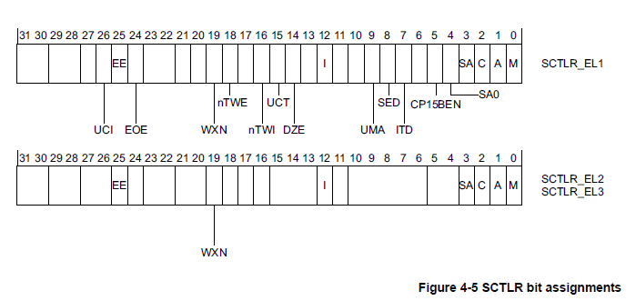
Not all bits are available above EL1. The individual bits represent the following :
UCI When set, Enable EL0 access in AArch64 for DC CVAU, DC, CIVAC, DC CVAC, and IC IVAU instructions.
EE Exception endianness
<0> Little endian
<1> Big endian
EOE Endianness of explicit data access at EL0. The possible values of this bit are :
0 Explicit data access at EL0 are liitle - endian.
1 Explicit data acceses at EL0 are big-endian.
WXN Write permission implies XN(eXecute Never).
0 Regions with write permission are not forced to XN.
1 Regions with write permission are forced to XN.
nTWE Not trap WFE. A value of 1 means that WFE instructions are executed as normal.
nTWI Not trap WFI. A value of 1 means that WFI instructions are executed as normal.
UCT When set, enables EL0 access in AArch64 to the CTR_EL0 register.
DZE Access to DC ZVA instruction at EL0.
0 Execution prohibited
1 Execution allowed/
I Instruction cache enable. This is an enable bit for instruction caches at EL0 and EL1. Instruction accesses to cacheable Normal memory are cached.
UMA User Mask Access. Controls access to interrupt masks from EL0, when EL0 is using AArch64.
SED SETEND Disable. Disables SETEND insturctions at EL0 using AArch32.
0 SETEND instructions are enabled.
1 The SETEND instruction is disabled.
ITD IT Disable. The possible values of this bit are :
0 The IT instruction is available.
1 The IT instruction is treated as a 16-bit instruction.
CP15BEN CP15 barrier enable. If implemneted, it is an enable bit for the AArch32 CP15 DMB,DSB, and ISB barrier operations.
SA0 Stack Alignment Check Enable for EL0.
SA Stack Alignment Check Enable.
C Data Cache enable. This is an enable bit for data caches at EL0 and EL1. Data accesses to cacheable Normal memory are cached.
A Alignment check enable bit.
M Enable the MMU.
Accessing the SCTLR
To accessing the SCTLR_ELn, use :
MRS , SCTLR_ELn // Read sCTLR_ELn into Xt
MRS X0, SCTLR_EL1	// Read System Control Register Configuration Data
ORR X0, X0, #(1 << 2)	// Set [C] bit and enable data caching.
ORR X0, X0, #(1 << 12) // Set [I] bit and enable instruction caching
MSR SCTLR_EL1, X0 // Write System Control Regster configuration data.
  UCI (UCI): 이 비트가 설정되면 AArch64에서 EL0에서 DC CVAU, DC CIVAC, DC CVAC, IC IVAU 명령에 대한 액세스를 허용합니다. 이 명령들은 캐시 관리에 사용되며, 이 비트가 설정되어야 EL0에서 해당 명령을 실행할 수 있습니다.

EE (Exception endianness): 이 비트는 예외 발생 시 사용되는 엔디안을 나타냅니다. 0은 리틀 엔디안을, 1은 빅 엔디안을 의미합니다. 엔디안은 데이터의 바이트 순서를 가리키며, 예외 처리 동안에 어떤 엔디안을 사용할지를 결정합니다.

EOE (Endianness of explicit data accesses at EL0): 이 비트는 EL0에서 명시적 데이터 액세스의 엔디안을 나타냅니다. 0은 EL0에서 명시적 데이터 액세스가 리틀 엔디안을 사용하고, 1은 빅 엔디안을 사용함을 의미합니다. 명시적 데이터 액세스는 EL0에서 직접적으로 수행되는 데이터 액세스를 의미합니다.

WXN (Write permission implies XN): 이 비트는 쓰기 권한이 XN (eXecute Never)을 의미하는지 여부를 결정합니다. 0은 쓰기 권한이 XN을 강제로 할 필요가 없음을 의미하며, 1은 쓰기 권한이 XN을 강제로 합니다. XN은 해당 영역의 코드 실행을 막는 기능으로 사용됩니다.

nTWE (Not trap WFE): 이 비트가 1로 설정되면 WFE (Wait For Event) 명령이 트랩되지 않고 일반적으로 실행됩니다. WFE 명령은 대기 상태로 전환하여 이벤트가 발생할 때까지 실행을 중지하는 역할을 합니다.

nTWI (Not trap WFI): 이 비트가 1로 설정되면 WFI (Wait For Interrupt) 명령이 트랩되지 않고 일반적으로 실행됩니다. WFI 명령은 인터럽트가 발생할 때까지 실행을 중지하는 역할을 합니다.

UCT (User Configuration): 이 비트가 설정되면 AArch64에서 EL0에서 CTR_EL0 레지스터에 액세스할 수 있습니다. CTR_EL0 레지스터는 캐시 관련 정보를 저장하는 레지스터입니다.

DZE (Access to DC ZVA instruction at EL0): 이 비트가 1로 설정되면 EL0에서 DC ZVA (Data Cache Zero by Virtual Address) 명령에 대한 액세스가 허용됩니다. DC ZVA 명령은 특정 가상 주소 범위의 데이터 캐시 라인을 0으로 초기화하는 역할을 합니다.

I (Instruction cache enable): 이 비트는 명령 캐시를 활성화하는 비트입니다. EL0과 EL1에서 캐시 가능한 일반 메모리에 대한 명령 액세스를 캐싱합니다.

UMA (User Mask Access): 이 비트는 EL0이 AArch64를 사용할 때 EL0에서 인터럽트 마스크에 액세스할 수 있는지 여부를 제어합니다. 인터럽트 마스크는 인터럽트 처리를 제어하는데 사용되는 비트 집합입니다.

SED (SETEND Disable): 이 비트가 1로 설정되면 EL0에서의 SETEND 명령을 비활성화합니다. SETEND 명령은 AArch32 모드에서 사용되며, 엔디안을 전환하는데 사용됩니다.
Endianness
There are two basic wats of veiwing bytes in memory, either as LE or BE.
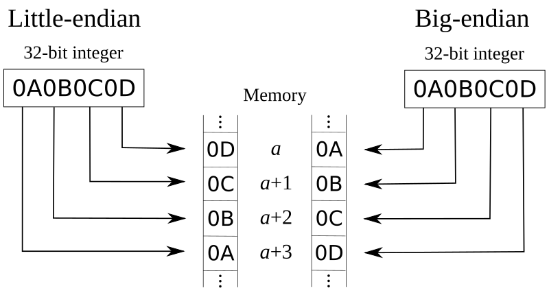
This data endianness os controlled independently for each Execution level. For EL3, EL2 and EL1, the relevant register of SCTLR_ELn. EE sets the endianness.
The additional bit at EL1, SCTLR_EL1,E0E controls the data endian setting for EL0. In the AArch64 executin state, data accesses can be LE or Be, while instruction fetches are always LE.
Whether a processor supports both LE and BE depends upon the implementation of the processor. If only little endianess is supported, then the EE and E0E bit are always 0.
Similarly, if only big-endianess m then the EE and E0e bits are at a static 1 value.
When using AArch32, having the CPSR_E bit have a different value to the equivalent System Control register EE bit When in EL1, EL2, or EL3 is now deprecated. The use of the ARM v7 SETEND instruction is also deprecated. It is possible to cause the Undef exception to be taken upon executing a SETEND instruction, by setting the SCTLR SED bit.
Changing Execution state( again )
In Changing execution state on page 3-8, we descrived the change between AArch 64 and AArch 32 in terms for Exception levels. Noew we consider the change from the point of view of the registers.
On entry to an Exception level using AArch64 from an Exception level using AArch 32 :
The values of the upper 32 bits of registers that were accessible to any lower Exception level using AArc32 execution are UNKNOWN.
The registers that are not accessible during AArch32 execution retain the state that they had before AArch32 execution.
AArch64 Stack Pointer(SPs) and Exception Link Register(ELRs) associated with an Exception level that is not accessible during AArch32 execution, at that Exception level, retain the state that they had before AArch32 execution.
-
SP_EL0.
-
SP_EL1.
-
SPEL2.
ELR_EL1.In general, application programmers write applications for either AArch32 or AArch64. It is only the OS that musk take account of the two execution states and the swtich between them.
AArch64를 사용하여 AArch32를 사용하는 예외 수준으로 진입할 때 다음과 같은 사항을 고려해야 합니다:
AArch32 실행 중 하위 예외 수준에서 접근할 수 있는 레지스터의 상위 32비트 값은 알 수 없는 상태입니다.
AArch32 실행 중 접근할 수 없는 레지스터는 AArch32 실행 이전의 상태를 유지합니다.
AArch32를 사용하던 상태에서 EL2가 AArch32를 사용하는 EL3으로 예외 진입할 때, ELR_EL2의 상위 32비트 값은 알 수 없는 상태입니다.
AArch32 실행 중 접근할 수 없는 예외 수준의 AArch64 스택 포인터(SP) 및 예외 링크 레지스터(ELR)는 해당 예외 수준에서 AArch32 실행 이전의 상태를 유지합니다. 이는 다음 레지스터에 적용됩니다:
SP_EL0.
SP_EL1.
SP_EL2.
ELR_EL1.
일반적으로 응용 프로그래머는 AArch32 또는 AArch64를 대상으로 응용 프로그램을 작성합니다. 두 실행 상태와 그 사이의 전환을 고려해야 하는 것은 운영 체제뿐입니다.
