SystemVerilog - 0
Overview of the book
The systemVerilog Language includes features for design, verification, assertion, and more. This book focuses on the constructs used to verify a design. There are many ways to solve a problem using SystemVerilog. This book expains the trade-offs between alternative solutions.
Chapter 1, Verification Guidelines, presents verification techniques to serve as a foundation for learning and using the SystemVerilog language.
Chapter 2, Data Types, covers the new System Verilog data types such as arrays, structures, enumerated types, and packed variables.
Chapter 3 , Procedural Statements and Routines, shows the new procedural statements and improvements for tasks and functions.
Chapter 4 , Basic OOP, is an introduction to Object Oriented Programming, explaining how to build classes, construct objects, and use handles.
Chapter 5, Connecting the Testbench and Desgin, shows the new SystemVerilog verification constructs, such as program blocks, interfaces, and clocking blocks, and how they are used to build your testbench and connect it to the design under test.
Chapter 6, Randomization, shows you how to use System Verilog's constrained-random stimulus generation, including many techniques and examples.
Chapter 7, Threads and Interprocess Communication, shows how to create multiple threads in your testbench, use interprocess communication to exchange data between these threads and synchronize them
Chapter 8, Advanced OOP and Guidelines, shows how to build a layered testbench with OOP's ingeritance so that the components can be shared by all tests.
Chapter 9, Functional Coverage, explains the different types of coverage and how you can use functional coverage to measure your progress as you follow a verificaiton plan.
Chapter 10, Adcanced Interfaces, shows how to use virtual interfaces to simplify your testbench code, connect to multiple design configurations, and create interfaces with procedural code so your testbench and design can work at a higher level of abstraction.
- Constrained-random stimulus generation
- Functional coverage
- Higher-level structures, especially Object Oriented Programming
- Multi-threading and interprocess communication
- Support for HDL types such as Verilog's 4-state values
- Tight integration with event-simulator for control of the design.
1.2 The Verification Process
1.5 Basic Testbench Functionality
The purpose of a testbench is to determine the correctness of the desgin under test. This is accomplished by the following steps.
- Generate stimulus
- Apply Stimulus to the DUT
- Capture the response
- Check for correctness
- Measure progress against the overall verification goals
Some steps are accomplished automatically by the testbench, while others are manually determined by you,
1.6 Directed Testing
1.12.2 The signal and command layers
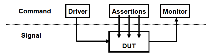
At the bottom is the signal layer that contains the design under test and the signals that connect it to the testbench.
the next level up is the command layer. The DUT's inputs are driven by the driver that runs single commands such as bus read or write. The DUT's output drives the monitor that takes signal transition and groups them together into commands. Assertions also cross the command/signal layer, as they look at individual signals but look for changes across and entire command.
1.12.3 The functional layer
The functional layer feeds the command layer. The agent block(called the ransacotr in the VMM) receives higher-level transactions such as DMA read or write and breaks them into individual commands. These commands are also sent to the scoreboard that predicts the results of the transaction.
1.12.4 The scenario layer
The functional layer is driven by the generator in the scenario layer. What is a scenario? Remember that your job as a verificaiton engineer is to make sure that this device accomplishes its intended task.
For example,
Downloading a music file takes several steps, such as contorl register reads and writes to set up the operation, multiple DMA writes to transfer the song, and then another group of reads and writes. The scenario layer of your testbench orchestrates all these steps with constrained-random values for parameters such as track size and memory location
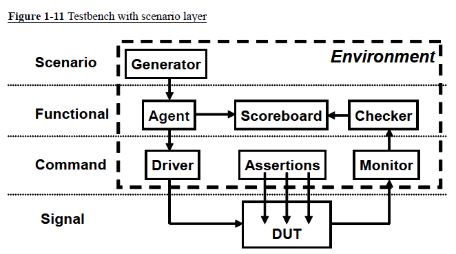
The blocks in the testbench enviroment(inside the dashed line) are written at the start of development. During the project they may evolve and you may add functionality,but these blocks should not change for indicidual tests. This is done by leaving "hooks" in the code so that a test can change the behavior of these blocks without having to rewrite them. You create these hooks with callbacks and factory patterns.
1.12.5 The test layer and functional coverage
You are now at the top of the testbench, the test layer, as shown in Figure. 1-12 Design bugs that occur between DUT blocks are harder to find as they involve multiple people reading and interpreting multiple specifications.
The top-level test is a conductor who does not play any musical instrument, but instead guides the efforts of others. The test contains the constraints to create the stimulus.
Functional coverage measures the progress of all tests in fullfiling the requirements in the verification plan. The functional coverage code changes through the project as the various criteria compete. Because it is constantly being modified, it is not part of the environment.
You can create a "directed test" in a constrained-random environment. Simply insert a section of directed test case into the middle of or in parallel with a random sequence. The directed code performs the work you wnat, but the random " background noise " may cause a bug to become visible, perhaps in an unanticipated block.
Do you need all these layers in your testbench? The answer depends on what your DUT looks like. A complicated design requires a sophisticated testbench. You always need the test layer. For a simple design, the scenario layer may be so simple that you can merge it with the agent. When estimating the effort to test a design, don;t count the number of gates; count the number of designers.
You may need more layers. If your DUT has several protocol layers, each should get its own layer in the testbench environment. For example, if you have TCP traffic that is wrapped in IP and set in Ethernet packets, consider using three separate layers for generation and checking. Better yet, use existing verification components.
One last note about the above diagram : It shows some of the possible connections between blocks, but your testbecnch may have a different set. The test may need to reach down to the driver layer to force physical errors.
1.13 Building a Layered Testbench
Now it is time to take the previous diagrams and learn how to map the components into System Verilog constructs
1.13.1 Creating a simple driver

The driver receives commands from the agent, may inject errors or add delays, and then breaks the commnad down into individual signal changes such as bus request, handshakes, etc. The general term for such a testbench block is a "transactor," which, at its core, is a loop :
task run();
done = 0;
while(!done) begin
// Get the next transaction
// Make transformations
// Send out transactions
end
endtask
Chapter 4 presents basic OOP and how to create an object taht includes the routines and data for a transactor. Another example of a transactor is the agent. It might break apart a complex transaction such as a DMA read into multiple bus commands Also in Chapter 4, you will see how to build an object that contains the dta and routines that make up a command. These objects are sent between transactors using System Veriog mailboxes. In Chapter 7, you will learn about many ways to exchange data between the different layers and to synchronize the transactors.
1.14 Simulation Environment Phases
Up until now you have been learning what parts make up the environment. When do these parts execute? You want to clearly define the pahses to coordinate the testbench so all the code for a project works together. The three primary phases are build, run, and wrap-up. Each is divided into smller steps.
The Build phase is divided into the following steps :
Generate Configuration : randomize the configuration of the DUT and the surrounding environment.
Build Environment: Allocate and connect the testbench components based on the configuration. A testbench component is one that only exists in the testbench, as opposed to physical components in the design that are built with RTL code. For example, if the configuration chose three bus drivers, the testbench would allocate and initialize them in this step.
Reset the DUT.
-
Configure the DUT based on generated configuration from the first step.
The Run phase is where the test actually runs. It has the following steps :
Start environment : run the testbench components such as BFMs and stimulus generators.
Run the test : start the test and then wait for it to complete. It is easy to tell when a directed test has completed, but doing so can be complex for a random test. You can use the testbench layers as a guide. Starting from the top, wait for a layer to drain all the inputs from the previous layer(if any), wait for the current layer to become idle, and then wait for the next lower layer. You should also use time-out checkers to ensure that the DUT or testbench does not lock up.
The Wrap - up phase has two steps :
Sweep : After the lowest layer completes, you need to wait for the final transactions to drain out of the DUT.
Report : Once the DUT is idle, sweep the testbench for lost data.
Sometimes the scoreboard holds transactions that never came out, perhaps becuase they were dropped by the DUT. With this information you can create the final report on whether the test passed or failed. If it failed, be sure to delete any functional coverage data, as it may not be correct
