이번 실험은 Common 단자를 이용하여 ROW와 COL이 같은 곳에 LED를 켜는 것이다. 그리고 도트 매트릭스에 X모양으로도 LED를 켠다.
스케치 8-4 도트 매트릭스의 COL 방향 LED 켜기
byte col = 0;
byte leds[8][8];

// pin[xx] on led matrix connected to nn on Arduino
// (-1 is dummy to make array start at pos 1)
int pins[17]= {-1, 5, 4, 3, 2, 14, 15, 16, 17, 13, 12, 11, 10, 9,8, 7, 6};

// row[xx] of leds = pin yy on led matrix
int rows[8] = {pins[9], pins[14], pins[8], pins[12], pins[1],pins[7], pins[2], pins[5]};

// col[xx] of leds = pin yy on led matrix
int cols[8] = {pins[13], pins[3], pins[4], pins[10], pins[06],pins[11], pins[15], pins[16]};

void setup() {
  // put your setup code here, to run once:
  for (int i = 1; i <= 16; i++) {
    pinMode(pins[i], OUTPUT);
  }
  for (int i = 1; i <= 8; i++) {
    digitalWrite(cols[i - 1], HIGH);
  }
  // set up cols and rows
  for (int i = 1; i <= 8; i++) {
    digitalWrite(rows[i - 1], LOW);
  }
}
void loop() {
  for (int i = 0; i < 8; i++) {
    digitalWrite(rows[i], HIGH);
    digitalWrite(cols[0], LOW);
  }
}
스케치 8-4 분석
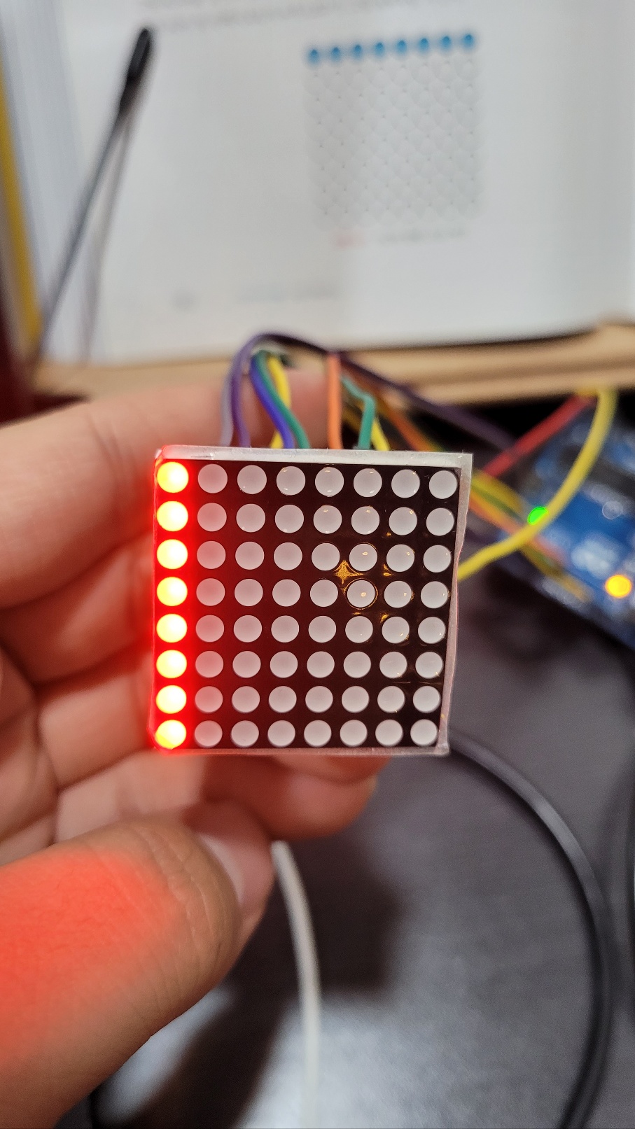
COL 1에 LOW 그리고 그리고 8개의 ROW에 HIGH를 입력하면 전류가 흐르게 되어 첫번째 ROW의 LED가 켜진다.
스케치 8-4 실행결과
스케치 8-5 도트 매트릭스의 ROW 방향 LED 켜기
byte col = 0;
byte leds[8][8];

// pin[xx] on led matrix connected to nn on Arduino
// (-1 is dummy to make array start at pos 1)
int pins[17]= {-1, 5, 4, 3, 2, 14, 15, 16, 17, 13, 12, 11, 10, 9,8, 7, 6};

// row[xx] of leds = pin yy on led matrix
int rows[8] = {pins[9], pins[14], pins[8], pins[12], pins[1],pins[7], pins[2], pins[5]};

// col[xx] of leds = pin yy on led matrix
int cols[8] = {pins[13], pins[3], pins[4], pins[10], pins[06],pins[11], pins[15], pins[16]};

void setup() {
  // put your setup code here, to run once:
  for (int i = 1; i <= 16; i++) {
    pinMode(pins[i], OUTPUT);
  }
  for (int i = 1; i <= 8; i++) {
    digitalWrite(cols[i - 1], HIGH);
  }
  // set up cols and rows
  for (int i = 1; i <= 8; i++) {
    digitalWrite(rows[i - 1], LOW);
  }
}
void loop() {
  for (int i = 0; i < 8; i++) {
    digitalWrite(rows[0], HIGH);
    digitalWrite(cols[i], LOW);
  }
}
스케치 8-5 분석
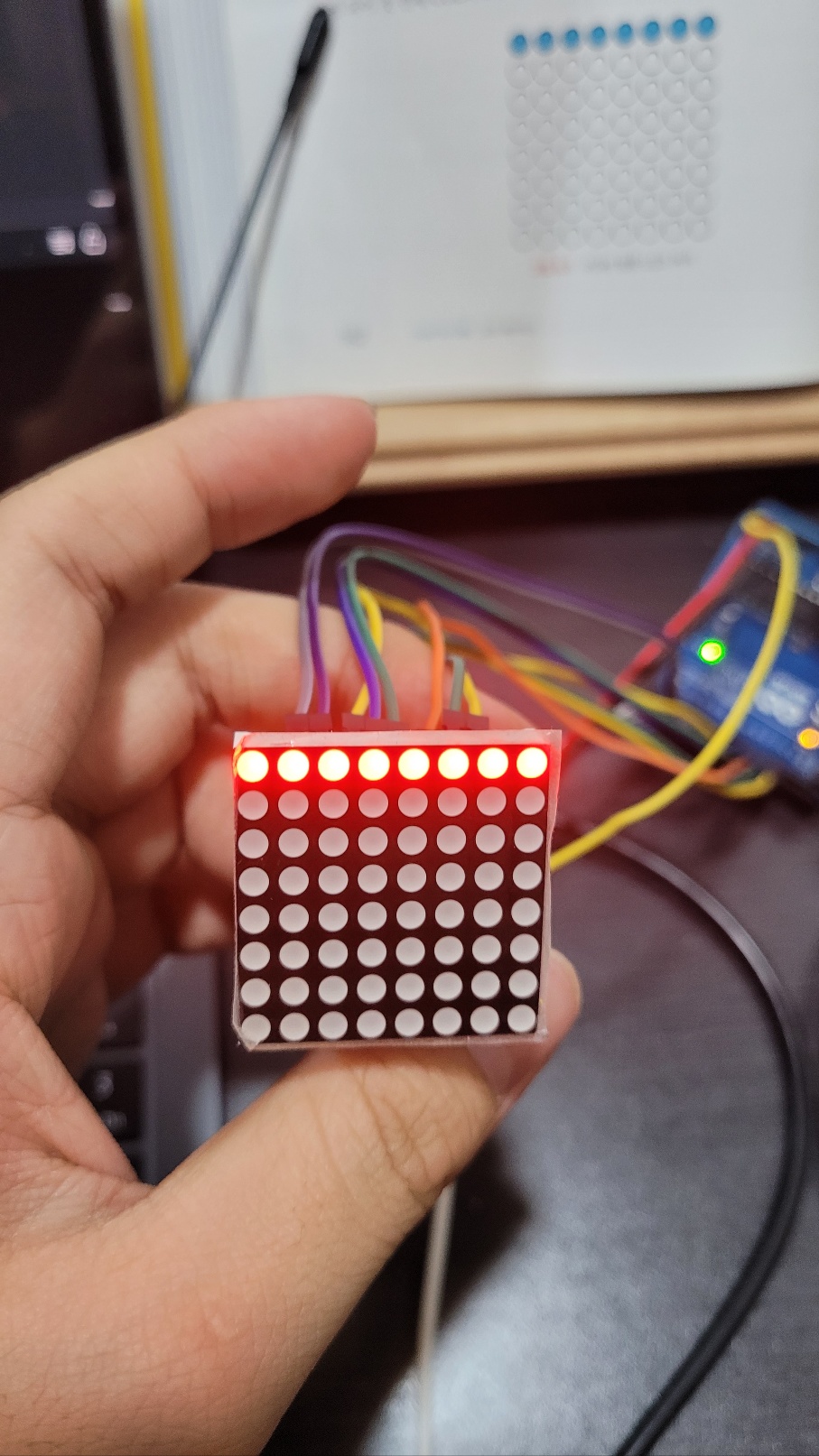
ROW 1에 HIGH 그리고 8개의 COL에 LOW을 입력하면 전류가 흐르게 되어 첫 번째 COL의 8개 LED가 켜진다.
스케치 8-5 실행결과
스케치 8-6 도트 매트릭스의 대각선 방향 LED 켜기
byte col = 0;
byte leds[8][8];
// pin[xx] on led matrix connected to nn on Arduino
// (-1 is dummy to make array start at pos 1)
int pins[17]= {-1, 5, 4, 3, 2, 14, 15, 16, 17, 13, 12, 11, 10, 9,8, 7, 6};
// row[xx] of leds = pin yy on led matrix
int rows[8] = {pins[9],pins[14],pins[8],pins[12],pins[1],pins[7],pins[2],pins[5]};
// col[xx] of leds = pin yy on led matrix
int cols[8] = {pins[13],pins[3],pins[4],pins[10],pins[06],pins[11],pins[15],pins[16]};
void setup() {
// put your setup code here, to run once:
for (int i = 1; i <= 16; i++) {
pinMode(pins[i], OUTPUT);
}
for (int i = 1; i <= 8; i++) {
digitalWrite(cols[i - 1], HIGH);
}
// set up cols and rows
for (int i = 1; i <= 8; i++) {
digitalWrite(rows[i - 1], LOW);
}
}
void loop() {
for (int i = 0; i < 8; i++) {
for (int j = 0; j < 8; j++) {
if (i == j) {
digitalWrite(rows[7-j], HIGH);
digitalWrite(rows[j], HIGH);
digitalWrite(cols[i], LOW);
}
digitalWrite(rows[7-j], LOW);
digitalWrite(rows[j], LOW);
digitalWrite(cols[i], HIGH);
}
}
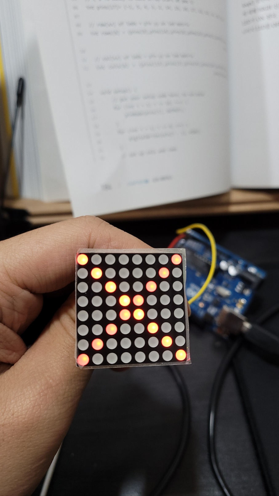
}스케치 8-6 분석
loop( ) 함수의 두 번째 for문 안에서 ROW와 COL이 같은 경우 ROW가 7-j번째인 경우에 대해 HIGH 신호를 그리고 COL에 대해서는 LOW 신호를 입력하면 전류가 흐르게 되어 LED가 ON 된다. 그러나 대각선 이외의 LED는 OFF가 되어야 하므로 두 번째 for문 안에 나머지 LED를 OFF 시키는 3개 문장을 넣웆ㄴ다.
스케치 8-5 실행결과

Shine like a star, Just like a star