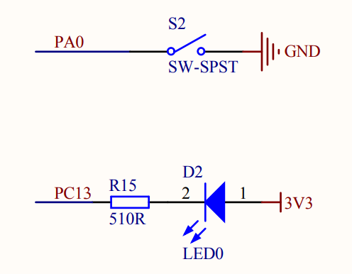
- 개발보드 회로도
1. GPIO 설정
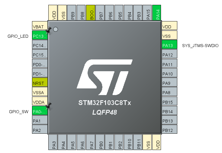
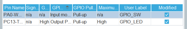
개발보드에 있는 SW를 PA0에, LED를 PC13에 설정해주었다.
SW: GPIO INPUT MODE
LED: GPIO OUTPUT MODE
설정을 해주면 코드가 알아서 생성된다.
2. HAL 드라이버로 GPIO 분석
1) MX_GPIO_Init 분석
static void MX_GPIO_Init(void)
{
  GPIO_InitTypeDef GPIO_InitStruct = {0};
/* USER CODE BEGIN MX_GPIO_Init_1 */
/* USER CODE END MX_GPIO_Init_1 */

  /* GPIO Ports Clock Enable */
  __HAL_RCC_GPIOC_CLK_ENABLE();
  __HAL_RCC_GPIOA_CLK_ENABLE();

  /*Configure GPIO pin Output Level */
  HAL_GPIO_WritePin(GPIO_LED_GPIO_Port, GPIO_LED_Pin, GPIO_PIN_SET);

  /*Configure GPIO pin : GPIO_LED_Pin */
  GPIO_InitStruct.Pin = GPIO_LED_Pin;
  GPIO_InitStruct.Mode = GPIO_MODE_OUTPUT_PP;
  GPIO_InitStruct.Pull = GPIO_PULLUP;
  GPIO_InitStruct.Speed = GPIO_SPEED_FREQ_HIGH;
  HAL_GPIO_Init(GPIO_LED_GPIO_Port, &GPIO_InitStruct);

  /*Configure GPIO pin : GPIO_SW_Pin */
  GPIO_InitStruct.Pin = GPIO_SW_Pin;
  GPIO_InitStruct.Mode = GPIO_MODE_INPUT;
  GPIO_InitStruct.Pull = GPIO_PULLUP;
  HAL_GPIO_Init(GPIO_SW_GPIO_Port, &GPIO_InitStruct);

/* USER CODE BEGIN MX_GPIO_Init_2 */
/* USER CODE END MX_GPIO_Init_2 */
}
(1) GPIO 포트 CLOCK 활성화
 /* GPIO Ports Clock Enable */
  __HAL_RCC_GPIOC_CLK_ENABLE();
  __HAL_RCC_GPIOA_CLK_ENABLE();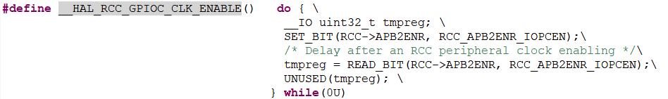
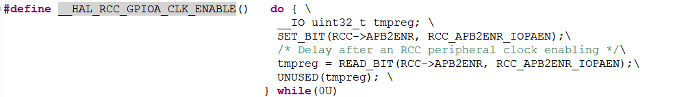
중요 포인트 SET_BIT
/*GPOPC*/
SET_BIT(RCC->APB2ENR, RCC_APB2ENR_IOPCEN);

/*GPIOA*/
SET_BIT(RCC->APB2ENR, RCC_APB2ENR_IOPAEN);#define SET_BIT(REG, BIT) ((REG) |= (BIT))or 연산을 하는 코드이다.
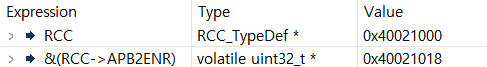

GPIOC
REG = RCC->APB2ENR = 0x40021018
BIT = RCC_APB2ENR_IOPCEN = 16

*(0x40021018) |= (1<<4) : BIT 4 활성화
GPIOA
REG = RCC->APB2ENR = 0x40021018
BIT = RCC_APB2ENR_IOPAEN = 4

*(0x40021018) |= (1<<2) : BIT 2 활성화
결론
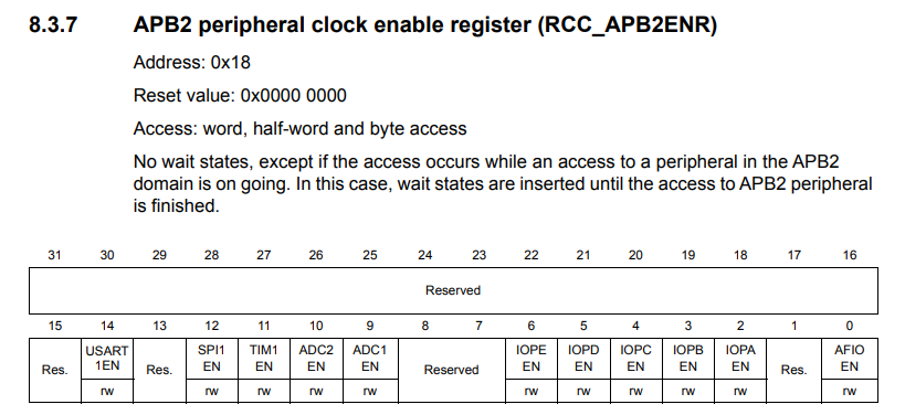

RCC_APB2ENR (APB2 Peripheral Clock Enable Register)는 STM32 마이크로컨트롤러에서 APB2(Advanced Peripheral Bus 2)에 연결된 다양한 주변 장치의 클럭을 활성화하거나 비활성화하는 역할을 하는 레지스터이다.
이 레지스터는 RCC(Reset and Clock Control) 모듈의 일부로, 시스템의 주변 장치 클럭을 관리한다.
따라서 PORT A의 클럭을 활성화 시키기 위해서는 BIT 2를 활성화해야 하고,
PORT C의 클럭을 활성화 시키기 위해서는 BIT 4를 활성화해야 한다.
그래서
*(0x40021018) |= (1<<2) : BIT 2 활성화
*(0x40021018) |= (1<<4) : BIT 4 활성화
이러한 코드가 나온 것이다.
시스템 구조
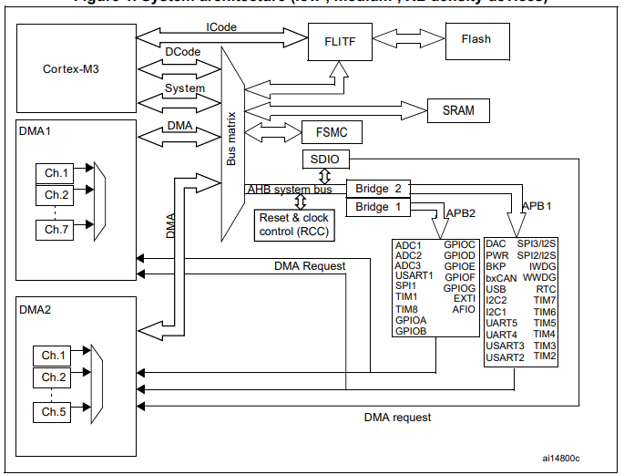
장치마다 클럭이 다르기 때문에 클럭 속도마다 연결되는 버스가 다르다.
* APB 란?
APB는 CPU와 주변 장치 간의 통신을 효율적으로 처리하는 역할을 한다.
APB1 : 상대적으로 속도가 낮은 장치들과 연결된다.
APB2 : 고속장치들이 연결된다.
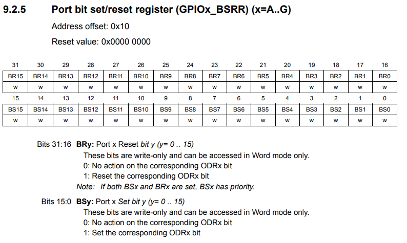
(2) LED 값 설정
/*Configure GPIO pin Output Level */
  HAL_GPIO_WritePin(GPIO_LED_GPIO_Port, GPIO_LED_Pin, GPIO_PIN_SET);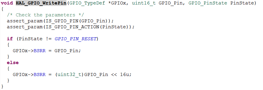
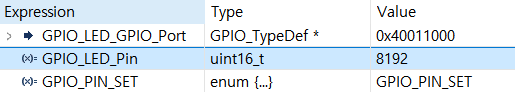
GPIO_LED_GPIO_Port : 0x40011000
GPIO_LED_GPIO_Port ->BSRR : 0x40011010
GPIO_LED_Pin : 8192 = binary 1000000000000 : BIT 13
GPIO_PIN_SET : 1
PC13 포트를 제어한다.
중요포인트
if (PinState != GPIO_PIN_RESET)
  {
    GPIOx->BSRR = GPIO_Pin;
  }
  else
  {
    GPIOx->BSRR = (uint32_t)GPIO_Pin << 16u;
  }
PinState 가 1이면 GPIOx_BSRR에서 BIT 13(BS13)에 1을 넣어라 = set
PinState 가 0이면 GPIOx_BSRR에서 BIT 29(BR13)에 1을 넣어라 = reset
(3) 중간 점검 - 클럭 활성화, LED 깜빡거리기
/* Initialize all configured peripherals */
  //MX_GPIO_Init();  //주석처리
  /* USER CODE BEGIN 2 */

  // __HAL_RCC_GPIOC_CLK_ENABLE(); 클럭 활성화
  volatile unsigned int * reg = 0x40021018;
  *reg |= 16;

  // 다음시간에 자세히 다룸
  GPIO_InitTypeDef GPIO_InitStruct = {0};
  GPIO_InitStruct.Pin = GPIO_LED_Pin;
  GPIO_InitStruct.Mode = GPIO_MODE_OUTPUT_PP;
  GPIO_InitStruct.Pull = GPIO_PULLDOWN;
  GPIO_InitStruct.Speed = GPIO_SPEED_FREQ_HIGH;
  HAL_GPIO_Init(GPIO_LED_GPIO_Port, &GPIO_InitStruct);
  /* USER CODE END 2 */

  /* Infinite loop */
  /* USER CODE BEGIN WHILE */

  volatile unsigned int *reg2 = 0x40011010;
  while (1)
  {
  	  //HAL_GPIO_WritePin();
	  *reg2 = 0x2000; //high - led off
	  HAL_Delay(1000);

	  *reg2 = (0x2000 << 16); // low - led on
	  HAL_Delay(1000);

    /* USER CODE END WHILE */

    /* USER CODE BEGIN 3 */
  }
  /* USER CODE END 3 */
}
이렇게하면 LED가 깜빡거리는 코드를 실행할 수 있다.
(4) configure 세팅
/*Configure GPIO pin : GPIO_LED_Pin */
  GPIO_InitStruct.Pin = GPIO_LED_Pin;
  GPIO_InitStruct.Mode = GPIO_MODE_OUTPUT_PP;
  GPIO_InitStruct.Pull = GPIO_PULLUP;
  GPIO_InitStruct.Speed = GPIO_SPEED_FREQ_HIGH;
  HAL_GPIO_Init(GPIO_LED_GPIO_Port, &GPIO_InitStruct);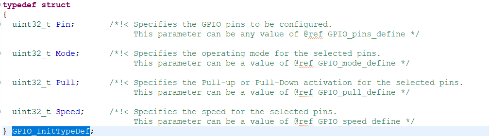
처음에 first.ioc 에서 LED를 GPIO OUTPUT 으로 설정할 때 옵션을 설정한 것을 자동으로 코드로 바꿔준 부분이다.
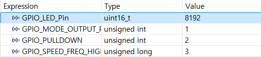
PIN = 8192 (= 1<<13) = 13번 핀을 설정 (PC13)
MODE = 1 : OUTPUT 옵션
PULL = 2 : PULLDOWN 옵션
SPEED = 3 : HIGH 옵션
HAL_GPIO_Init()
HAL_GPIO_Init(GPIO_LED_GPIO_Port, &GPIO_InitStruct);
위에서 설정한 옵션을 GPIO_LED_GPIO_Port로 넣어준다
이때 GPIO_LED_GPIO_Port는 GPIOC이다.

void HAL_GPIO_Init(GPIO_TypeDef  *GPIOx, GPIO_InitTypeDef *GPIO_Init)
{
  uint32_t position = 0x00u;
  uint32_t ioposition;
  uint32_t iocurrent;
  uint32_t temp;
  uint32_t config = 0x00u;
  __IO uint32_t *configregister; /* Store the address of CRL or CRH register based on pin number */
  uint32_t registeroffset;       /* offset used during computation of CNF and MODE bits placement inside CRL or CRH register */

  /* Check the parameters */
  assert_param(IS_GPIO_ALL_INSTANCE(GPIOx));
  assert_param(IS_GPIO_PIN(GPIO_Init->Pin));
  assert_param(IS_GPIO_MODE(GPIO_Init->Mode));

  /* Configure the port pins */
  while (((GPIO_Init->Pin) >> position) != 0x00u)
  {
    /* Get the IO position */
    ioposition = (0x01uL << position);

    /* Get the current IO position */
    iocurrent = (uint32_t)(GPIO_Init->Pin) & ioposition;

    if (iocurrent == ioposition)
    {
      /* Check the Alternate function parameters */
      assert_param(IS_GPIO_AF_INSTANCE(GPIOx));

      /* Based on the required mode, filling config variable with MODEy[1:0] and CNFy[3:2] corresponding bits */
      switch (GPIO_Init->Mode)
      {
        /* If we are configuring the pin in OUTPUT push-pull mode */
        case GPIO_MODE_OUTPUT_PP:
          /* Check the GPIO speed parameter */
          assert_param(IS_GPIO_SPEED(GPIO_Init->Speed));
          config = GPIO_Init->Speed + GPIO_CR_CNF_GP_OUTPUT_PP;
          break;

        /* If we are configuring the pin in OUTPUT open-drain mode */
        case GPIO_MODE_OUTPUT_OD:
          /* Check the GPIO speed parameter */
          assert_param(IS_GPIO_SPEED(GPIO_Init->Speed));
          config = GPIO_Init->Speed + GPIO_CR_CNF_GP_OUTPUT_OD;
          break;

        /* If we are configuring the pin in ALTERNATE FUNCTION push-pull mode */
        case GPIO_MODE_AF_PP:
          /* Check the GPIO speed parameter */
          assert_param(IS_GPIO_SPEED(GPIO_Init->Speed));
          config = GPIO_Init->Speed + GPIO_CR_CNF_AF_OUTPUT_PP;
          break;

        /* If we are configuring the pin in ALTERNATE FUNCTION open-drain mode */
        case GPIO_MODE_AF_OD:
          /* Check the GPIO speed parameter */
          assert_param(IS_GPIO_SPEED(GPIO_Init->Speed));
          config = GPIO_Init->Speed + GPIO_CR_CNF_AF_OUTPUT_OD;
          break;

        /* If we are configuring the pin in INPUT (also applicable to EVENT and IT mode) */
        case GPIO_MODE_INPUT:
        case GPIO_MODE_IT_RISING:
        case GPIO_MODE_IT_FALLING:
        case GPIO_MODE_IT_RISING_FALLING:
        case GPIO_MODE_EVT_RISING:
        case GPIO_MODE_EVT_FALLING:
        case GPIO_MODE_EVT_RISING_FALLING:
          /* Check the GPIO pull parameter */
          assert_param(IS_GPIO_PULL(GPIO_Init->Pull));
          if (GPIO_Init->Pull == GPIO_NOPULL)
          {
            config = GPIO_CR_MODE_INPUT + GPIO_CR_CNF_INPUT_FLOATING;
          }
          else if (GPIO_Init->Pull == GPIO_PULLUP)
          {
            config = GPIO_CR_MODE_INPUT + GPIO_CR_CNF_INPUT_PU_PD;

            /* Set the corresponding ODR bit */
            GPIOx->BSRR = ioposition;
          }
          else /* GPIO_PULLDOWN */
          {
            config = GPIO_CR_MODE_INPUT + GPIO_CR_CNF_INPUT_PU_PD;

            /* Reset the corresponding ODR bit */
            GPIOx->BRR = ioposition;
          }
          break;

        /* If we are configuring the pin in INPUT analog mode */
        case GPIO_MODE_ANALOG:
          config = GPIO_CR_MODE_INPUT + GPIO_CR_CNF_ANALOG;
          break;

        /* Parameters are checked with assert_param */
        default:
          break;
      }

      /* Check if the current bit belongs to first half or last half of the pin count number
       in order to address CRH or CRL register*/
      configregister = (iocurrent < GPIO_PIN_8) ? &GPIOx->CRL     : &GPIOx->CRH;
      registeroffset = (iocurrent < GPIO_PIN_8) ? (position << 2u) : ((position - 8u) << 2u);

      /* Apply the new configuration of the pin to the register */
      MODIFY_REG((*configregister), ((GPIO_CRL_MODE0 | GPIO_CRL_CNF0) << registeroffset), (config << registeroffset));

      /*--------------------- EXTI Mode Configuration ------------------------*/
      /* Configure the External Interrupt or event for the current IO */
      if ((GPIO_Init->Mode & EXTI_MODE) == EXTI_MODE)
      {
        /* Enable AFIO Clock */
        __HAL_RCC_AFIO_CLK_ENABLE();
        temp = AFIO->EXTICR[position >> 2u];
        CLEAR_BIT(temp, (0x0Fu) << (4u * (position & 0x03u)));
        SET_BIT(temp, (GPIO_GET_INDEX(GPIOx)) << (4u * (position & 0x03u)));
        AFIO->EXTICR[position >> 2u] = temp;


        /* Enable or disable the rising trigger */
        if ((GPIO_Init->Mode & RISING_EDGE) == RISING_EDGE)
        {
          SET_BIT(EXTI->RTSR, iocurrent);
        }
        else
        {
          CLEAR_BIT(EXTI->RTSR, iocurrent);
        }

        /* Enable or disable the falling trigger */
        if ((GPIO_Init->Mode & FALLING_EDGE) == FALLING_EDGE)
        {
          SET_BIT(EXTI->FTSR, iocurrent);
        }
        else
        {
          CLEAR_BIT(EXTI->FTSR, iocurrent);
        }

        /* Configure the event mask */
        if ((GPIO_Init->Mode & GPIO_MODE_EVT) == GPIO_MODE_EVT)
        {
          SET_BIT(EXTI->EMR, iocurrent);
        }
        else
        {
          CLEAR_BIT(EXTI->EMR, iocurrent);
        }

        /* Configure the interrupt mask */
        if ((GPIO_Init->Mode & GPIO_MODE_IT) == GPIO_MODE_IT)
        {
          SET_BIT(EXTI->IMR, iocurrent);
        }
        else
        {
          CLEAR_BIT(EXTI->IMR, iocurrent);
        }
      }
    }

	position++;
  }
}
while문
코드를 확인해보면 이렇게 긴데 while문부터 해석해보면,
  while (((GPIO_Init->Pin) >> position) != 0x00u){

  .
  .

  position++;
  }
binary
10000000000000 : GPIO_Init -> Pin , position == 0
01000000000000 position == 1
00100000000000 position == 2
00000000000001 position == 13
00000000000000 <- 이 때 while문 멈춤ioposition
ioposition = (0x01uL << position);binary
1 position == 0
10
100
1000
10000
10000000000000 position == 13iocurrent
iocurrent = (uint32_t)(GPIO_Init->Pin) & ioposition;GPIO_Init->Pin : 10 0000 0000 0000
ioposition은 1부터 ~ 10 0000 0000 0000까지
ioposition이 10 0000 0000 0000 이 아니라면 iocurrent == 0이다.
if문
if (iocurrent == ioposition)
    {

    }
-> iocurrent == ioposition 라는 것은 PIN 13번일 때를 찾는 코드였던것이다.
position == 13 일 때 if문에 들어갈 수 있다.
switch 문
/* Based on the required mode, filling config variable with MODEy[1:0] and CNFy[3:2] corresponding bits */
      switch (GPIO_Init->Mode)
      {
        /* If we are configuring the pin in OUTPUT push-pull mode */
        case GPIO_MODE_OUTPUT_PP:
          /* Check the GPIO speed parameter */
          assert_param(IS_GPIO_SPEED(GPIO_Init->Speed));
          config = GPIO_Init->Speed + GPIO_CR_CNF_GP_OUTPUT_PP;
          break;

        /* If we are configuring the pin in OUTPUT open-drain mode */
        case GPIO_MODE_OUTPUT_OD:
          /* Check the GPIO speed parameter */
          assert_param(IS_GPIO_SPEED(GPIO_Init->Speed));
          config = GPIO_Init->Speed + GPIO_CR_CNF_GP_OUTPUT_OD;
          break;

        /* If we are configuring the pin in ALTERNATE FUNCTION push-pull mode */
        case GPIO_MODE_AF_PP:
          /* Check the GPIO speed parameter */
          assert_param(IS_GPIO_SPEED(GPIO_Init->Speed));
          config = GPIO_Init->Speed + GPIO_CR_CNF_AF_OUTPUT_PP;
          break;

        /* If we are configuring the pin in ALTERNATE FUNCTION open-drain mode */
        case GPIO_MODE_AF_OD:
          /* Check the GPIO speed parameter */
          assert_param(IS_GPIO_SPEED(GPIO_Init->Speed));
          config = GPIO_Init->Speed + GPIO_CR_CNF_AF_OUTPUT_OD;
          break;

        /* If we are configuring the pin in INPUT (also applicable to EVENT and IT mode) */
        case GPIO_MODE_INPUT:
        case GPIO_MODE_IT_RISING:
        case GPIO_MODE_IT_FALLING:
        case GPIO_MODE_IT_RISING_FALLING:
        case GPIO_MODE_EVT_RISING:
        case GPIO_MODE_EVT_FALLING:
        case GPIO_MODE_EVT_RISING_FALLING:
          /* Check the GPIO pull parameter */
          assert_param(IS_GPIO_PULL(GPIO_Init->Pull));
          if (GPIO_Init->Pull == GPIO_NOPULL)
          {
            config = GPIO_CR_MODE_INPUT + GPIO_CR_CNF_INPUT_FLOATING;
          }
          else if (GPIO_Init->Pull == GPIO_PULLUP)
          {
            config = GPIO_CR_MODE_INPUT + GPIO_CR_CNF_INPUT_PU_PD;

            /* Set the corresponding ODR bit */
            GPIOx->BSRR = ioposition;
          }
          else /* GPIO_PULLDOWN */
          {
            config = GPIO_CR_MODE_INPUT + GPIO_CR_CNF_INPUT_PU_PD;

            /* Reset the corresponding ODR bit */
            GPIOx->BRR = ioposition;
          }
          break;

        /* If we are configuring the pin in INPUT analog mode */
        case GPIO_MODE_ANALOG:
          config = GPIO_CR_MODE_INPUT + GPIO_CR_CNF_ANALOG;
          break;

        /* Parameters are checked with assert_param */
        default:
          break;
      }
case GPIO_MODE_OUTPUT_PP:
/* Check the GPIO speed parameter */
assert_param(IS_GPIO_SPEED(GPIO_Init->Speed));
config = GPIO_Init->Speed + GPIO_CR_CNF_GP_OUTPUT_PP;
break;스위치 문의 목적은 config 값을 설정하기 위함이였다.
config 값 설정
config = GPIO_Init->Speed + GPIO_CR_CNF_GP_OUTPUT_PP;


/* GPIO_Init-> Speed == 3*/
#define  GPIO_SPEED_FREQ_HIGH             (GPIO_CRL_MODE0)   /*!< High speed */
#define GPIO_CRL_MODE0                       GPIO_CRL_MODE0_Msk
#define GPIO_CRL_MODE0_Msk                   (0x3UL << GPIO_CRL_MODE0_Pos)
#define GPIO_CRL_MODE0_Pos                   (0U)

/* GPIO_CR_CNF_GP_OUTPUT_PP == 0*/
#define  GPIO_CR_CNF_GP_OUTPUT_PP   0x00000000u /*!< 00: General purpose output push-pull  */
config = 3 + 0 = 3configregister, registeroffset
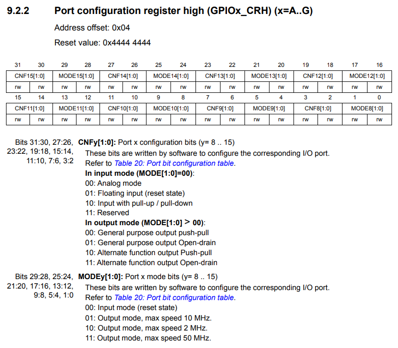
/* Check if the current bit belongs to first half or last half of the pin count number
       in order to address CRH or CRL register*/
      configregister = (iocurrent < GPIO_PIN_8) ? &GPIOx->CRL     : &GPIOx->CRH;
      registeroffset = (iocurrent < GPIO_PIN_8) ? (position << 2u) : ((position - 8u) << 2u);
configregister, registeroffset:
- GPIO PIN 8 미만이면 &GPIOx->CRL, (position << 2u)
- 이상이면 &GPIOx->CRH, ((position - 8u) << 2u)
13 pin이므로,
configregister = 0x40011004
registeroffset = 20

MODIFY_REG
/* Apply the new configuration of the pin to the register */
MODIFY_REG((*configregister), ((GPIO_CRL_MODE0 | GPIO_CRL_CNF0) << registeroffset), (config << registeroffset));#define MODIFY_REG(REG, CLEARMASK, SETMASK) WRITE_REG((REG), (((READ_REG(REG)) & (~(CLEARMASK))) | (SETMASK)))#define WRITE_REG(REG, VAL) ((REG) = (VAL))
#define READ_REG(REG) ((REG))
/* GPIO_CRL_MODE0 = (3<<0) = 3 */
#define GPIO_CRL_MODE0_Pos (0U)
#define GPIO_CRL_MODE0_Msk (0x3UL << GPIO_CRL_MODE0_Pos) /*!< 0x00000003 */
#define GPIO_CRL_MODE0 GPIO_CRL_MODE0_Msk
/* GPIO_CRL_CNF0 (3<<2) = 12 */
#define GPIO_CRL_CNF0_Pos (2U)
#define GPIO_CRL_CNF0_Msk (0x3UL << GPIO_CRL_CNF0_Pos) /*!< 0x0000000C */
#define GPIO_CRL_CNF0 GPIO_CRL_CNF0_Msk정리하면,
REG = *configregister = *0x40011004
CLEARMASK = (GPIO_CRL_MODE0 | GPIO_CRL_CNF0) << registeroffset = (3 | 12) << 20 = 15 << 20 = 15728640
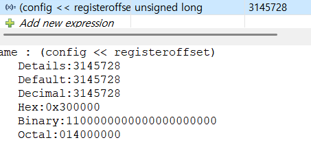
SETMASK = config << registeroffset = 3 << 20 = 3145728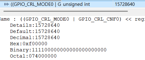
WRITE_REG(REG, (((READ_REG(REG)) & (~(CLEARMASK))) | (SETMASK)))

((READ_REG(REG)) & (~(CLEARMASK))) | (SETMASK))
: REG에 이미 설정된 값에 내가 설정하고싶은 값을 비트마스크로 CLEAR, SET을 하는 것이다.
*비트마스크
A & (~(B)) : CLEAR, RESET
만약 A : 11001110, B: 01100000이면
~(B) = 10011111
A &(~(B)) 10001110
A | B : SET
만약 A : 11001110, B: 01100000이면
A | B = 11101110
결론
HAL_GPIO_Init()은 핀 번호를 찾고,
config 값을 구한 후,
configregister의 값을 원하는 옵션으로 clear, set을 해주는 것이다.
*(configregister) = (*(configregister) & ~(CLEARMASK)) | (SETMASK);
*(0x40011004) = (*(0x40011004) & ~(15 << 20)) | (3 << 20);

GPIO Port C는 0x40011000 - 0x400113FF 주소에서 다룬다.
(5) 최종 - HAL 드라이버 없이 LED제어하기
/* Initialize all configured peripherals */
    //MX_GPIO_Init(); 주석처리
    /* USER CODE BEGIN 2 */

    // __HAL_RCC_GPIOC_CLK_ENABLE(); 클럭활성화
    volatile unsigned int * reg = 0x40021018;
    *reg |= 16;

    // Configure GPIO pin 핀 옵션
    volatile unsigned int * configreg = 0x40011004;
    *configreg = (*configreg & ~(15 << 20)) | (3 << 20);
    /* USER CODE END 2 */

    /* Infinite loop */
    /* USER CODE BEGIN WHILE */

    volatile unsigned int *reg2 = 0x40011010;
    while (1)
    {
    	  //HAL_GPIO_WritePin(GPIO_LED_GPIO_Port, GPIO_LED_Pin, GPIO_PIN_SET);
  	  *reg2 = 0x2000; //high - led off
  	  HAL_Delay(1000);

  	  *reg2 = (0x2000 << 16); // low - led on
  	  HAL_Delay(1000);

      /* USER CODE END WHILE */

      /* USER CODE BEGIN 3 */
    }
    /* USER CODE END 3 */
  }