
서론
사용 보드 : F429ZI
IDE : Keil MDK-ARM
Input Capture
받아들인 신호를 잡는다.
그럼 이것은 무엇이냐?
아두이노에서 생각하면
기존의 Input 은 loop를 돌면서 정해진 간격의 신호를 받아들인다.
하지만 그것은 내가 직접 계산한 타이밍을 잡아줘야한다.
다른 Input 방법으로 버튼 인터럽트를 사용하면
원하는 타이밍에 신호를 받을 수 있다.
하지만, 결과값을 알려면 millis() 함수를 사용하여 계산하여야한다.
그럼 일정한 규칙을 가진 신호를 원하는 타이밍에 받고 그 결과를 알고 싶으면 어떻게 해야하나?
그건,
정해진 간격을 기준점(Timer)으로 보고 비교하면
계산한 값을 넣지 않고 받은 신호로만 그 결과를 알 수 있다.
즉, Timer 로 신호의 주파수와 듀티를 구할 수 있다.
이러한 Input Capture 기능을 잘 보기 위해서는
초음파 센서가 어울린다.
쉽게 구할 수 있는
HC-SR04 를 이용하자.
초음파 센서
초음파 센서는 Trigger 에서 신호를 내보내면
반사되어 Echo 쪽으로 신호를 받아
High 가 측정된 시간을 계산하여
거리를 파악하는 센서이다.
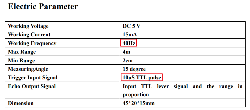
먼저 HC-SR04 초음파 센서의
▶ 작동 주파수(Working Frequency)
초음파 센서는 40Hz 이다.
40Hz 보다 느리게 신호를 줘야한다.
이 이유는 최대 거리(MAX Range) 4m 와 관련이 있는데
음속 : 340m/s
왕복거리 : 4m + 4m = 8m
거리 = 시간 x 속도
시간 = 거리 / 속도
최대거리 왕복 시간 = 8m / (340m/s) -> 계산하기 힘듬(약 0.0235s = 23ms)
최소거리 왕복 시간 = 0.04m/(340m/s) = 0.00011764s = 약 117 us
주파수 = 1/시간 = (340m/s)/8m = 42.5 Hz
라는 결과가 나온다.
즉, 왕복하는데 걸리는 최대 시간이
40Hz = 0.025 s = 25ms
이기 때문에 이 시간보다 빠르게(큰 주파수) 반복하면
센서는 인식할 수 "없-다" 는 말이다.
스텝모터의 주파수와는 의미가 다른데
스텝모터는 정해진 주파수에서 PWM으로 duty ratio만 조절하여
작동시킨다.
▶ 트리거 입력 신호(Trigger Input Signal)
Trigger 단자에 10us 의 TTL pulse를 내보내면
40kHz를 8번 내보내는 초음파가 생성된다.
TTL : Transistor-transistor logic
트랜지스터를 이용한 NAND 같은 논리 회로
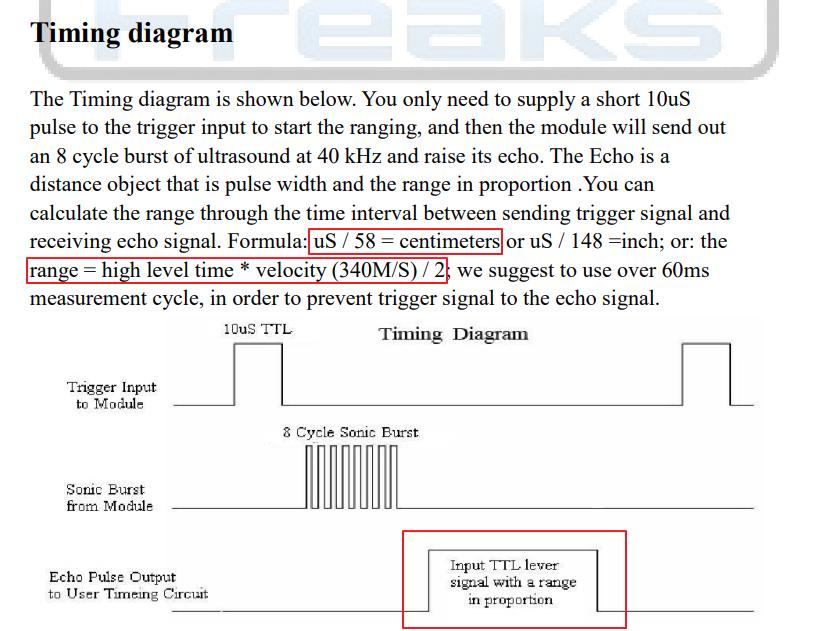
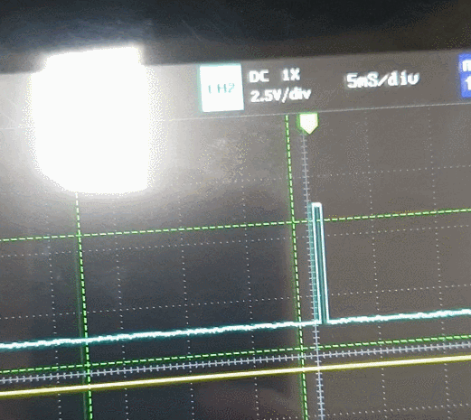
측정시간은 가장 밑 빨간 네모 부분이다.
측정 시간(us) / 58 -> cm
측정 시간(us) / 148 -> inch
거리 = 시간 x 속도
속도 = 소리의 속도(340m/s) / 2
최소 측정 사이클이 0.06s (60ms) <- 위에서는 25ms 라고 계산했지만
일반적으로 0.1 초로 잡으면 잘 측정될 것이다.
CubeMx 설정
1. TIM3 - Input Capture
Input Capture 를 사용하는 TIM3 의 경우
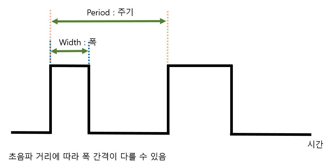
TIM3 주기 내에서 Rising(CH1)과 Falling(CH1) 이 측정되면
CCRx 레지스터에 값이 기록된다.
CCRx 값 사이의 간격을 이용하면 주기를 파악할 수 있다.
정확한 측정을 위해
Prescaler
Period
값을 알맞게 조절해야한다.
▶ prescaler 가 작으면
주파수 (f) 가 큼
-> 주기 (T) 가 짧음
-> 타이머가 빠르게 동작함
-> Counter Period 도 작게 했다면
-> 과한 updata Event 발생
-> Expired (만료) 된 클럭 발생
-> 측정 센서 또는 장비의 주기를 파악하기 힘듬
▶ prescaler 가 크면
분주되는 clock 의 주파수가 작아지기 때문에 (한 clock 시간 길어짐)
-> 작은 것을 모아서 크게 보는 것
-> 정밀도가 떨어진다.
측정하고자 하는 센서의 최소단위를 얻어야하기 때문에
필요 시간 간격 : 1us = 1MHz
TIM3 => APB1 Timer = 90MHz
prescaler = 90 ( 입력 : 90 - 1)
초음파를 0.1s 마다 보내고 있으니
Input capture가 발생하는 시간은 그 안쪽에 있다.
초음파의 한 주기보다 크기만 하면 Input Capture 값을 잘 측정할 수 있다.
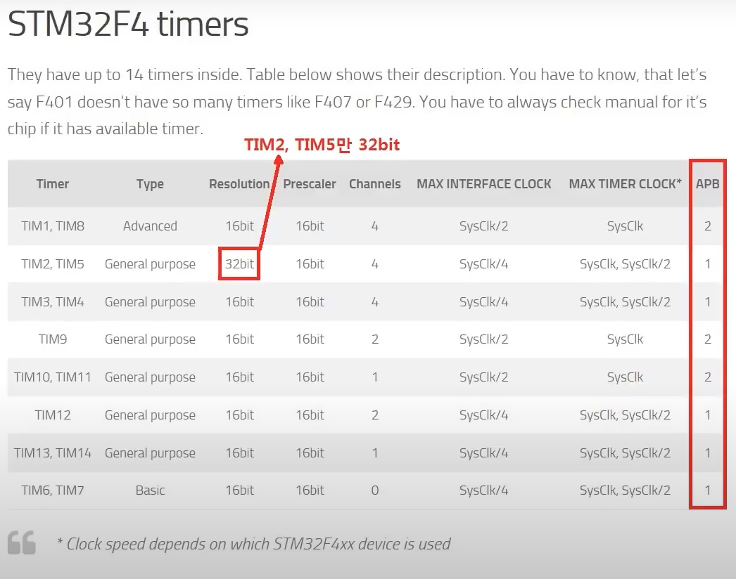
하지만, TIM3 는 16 bits 타이머라서
최대 Counter Period 값이 2^16 = 65536 ( 0 ~ 65535)
까지 밖에 안된다.
Counter Period = 65535
즉, Input Capture 의 타이머 카운터가 돌면서
Rising 과 Falling 을 측정하고
그 값을 DMA 에 넣어 저장하면
CPU 클럭 소모 없이 데이터를 얻을 수 있다.
Rising 과 Falling 을 측정할 Input Capture direct mode 를 선택한다.
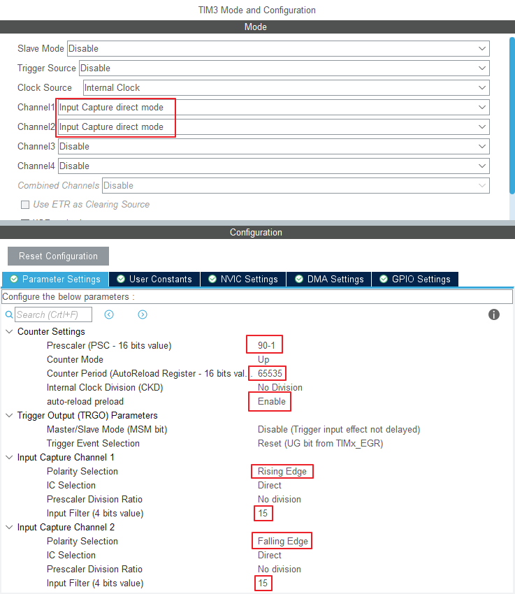
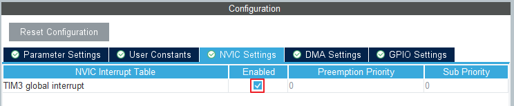
Interrupt 를 Enable 한다.
2. TIM4 - Trigger Output
초음파의 Trigger를 컨트롤하고자 사용하는 Timer 이다.
main 안에 넣기에는 지연시간이 생겨서 Timer로 분리 하고자 한다.
원하는 타이밍에 Output 신호를 내보내기 위해
Timer - Output Compare - Frozen Mode
로 설정한다.
방법 1.
Counter Period 값을 설정하고 Overflow 가 생기면
PeriodElapsedCallback 함수 내부에
Delay_us 함수를 만들어서 10us 생성
Timer 시간 = 초음파 시간
방법 2.
pulse 를 조절하여
PeriodElapsedCallback 함수 -> Trigger : HIGH
DelayElapsedCallback 함수 -> Trigger : LOW
HIGH - LOW 시간 간격 = 10us
Timer 시간 = 초음파 반복 시간
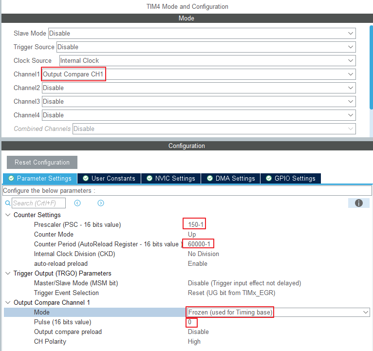
System Clock = 180MHz
APB1 Timer = 90MHz
원하는 시간 간격 = 0.1s
Prescaler = 150 -> (150-1 인 이유 : 0~149 => 150개)
분주된 시간 = 90,000,000 Hz / 150 = 600,000 Hz = 600kHz
Counter Period = 60000 (60000 -1)
Result = 600kHz/ 60000 = 10Hz => 0.1s
PeriodElapsedCallback 함수는 0.1s 마다 실행된다.
방법 2를 생각하면
여기에다가 가장 아래에 0으로 되어있는 Pulse (16 bits value) 를 설정하면된다.
Pulse -> CCR 값 ( Counter Period 의 한개 시간 간격 개수)
원하는 시간 간격 = 10us
0.1s -> 60000
0.00001s -> ?
Pulse = (0.00001s x 60000)/0.1s = 6
1us 마다 Pulse 0.6정도 증가
입력 : 6 - 1 = 5
11us = 6.6 -1 => 약 6 입력
=> 2번째 방법은 100ms 와 10us 시간 간격이 너무 크기 때문에 측정이 어렵다.
물론 가까이서 보면 잘 측정된다. 10us 보다 작아서 Pulse를 7정도로 하면 될 것 같다.
auto-reload preload => Enable
핀설정
PA6 -> TIM3_CH1
PC7 -> TIM3_CH2
PB6 -> GPIO_OUTPUT (LABEL : TRIGGER)
프로젝트 생성
Timer 함수
우리가 찾는 대부분의 기능은 HAL 드라이버 안에 있으니 잘 찾아보자.
위에서 말했다시피
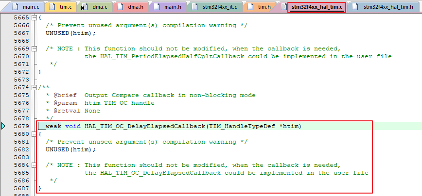
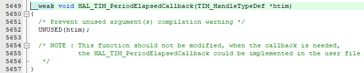
HAL_TIM_PeriodElapsedCallback 는 Counter_Period 를 넘어 Overflow가 발생했을 때
불러오고
HAL_TIM_OC_DelayElapsedCallback 는 pulse 로 정한 CCR 값에 도달했을 때 불러온다.
타이머를 시작하려면
HAL_TIM_Base_Start_IT(&사용타이머);
Output Compare Callback 함수를 사용하려면
HAL_TIM_OC_Start_IT(&사용타이머, 채널);
을 넣지 않으면 안된다.
HAL_TIM_Base_Start_IT(&htim4);
HAL_TIM_OC_Start_IT(&htim4, TIM_CHANNEL_1);
이 방식은 방법 2에 해당하는 것이다.
PeriodElapsedCallback -> 10ms
OC_DelayElapsedCallback - > 10us
void HAL_TIM_PeriodElapsedCallback(TIM_HandleTypeDef *htim)
{
	GPIOB->ODR |= 0x01 << 6;  // PB6 Trigger SET
}

void HAL_TIM_OC_DelayElapsedCallback(TIM_HandleTypeDef *htim)
{
	GPIOB->ODR &= ~(0x01 << 6);	// PB6 Trigger RESET
}
Delay_us
평소의 HAL_Delay() 가 ms 단위라면
DWT_Delay_us() 함수는 us 까지 입력가능하다.
uint32_t DWT_Delay_Init(void)
{
  /* Disable TRC */
  CoreDebug->DEMCR &= ~CoreDebug_DEMCR_TRCENA_Msk; // ~0x01000000;
  /* Enable TRC */
  CoreDebug->DEMCR |=  CoreDebug_DEMCR_TRCENA_Msk; // 0x01000000;

  /* Disable clock cycle counter */
  DWT->CTRL &= ~DWT_CTRL_CYCCNTENA_Msk; //~0x00000001;
  /* Enable  clock cycle counter */
  DWT->CTRL |=  DWT_CTRL_CYCCNTENA_Msk; //0x00000001;

  /* Reset the clock cycle counter value */
  DWT->CYCCNT = 0;

  /* 3 NO OPERATION instructions */
  __ASM volatile ("NOP");
  __ASM volatile ("NOP");
  __ASM volatile ("NOP");

  /* Check if clock cycle counter has started */
  if(DWT->CYCCNT)
  {
    return 0; /*clock cycle counter started*/
  }
  else
  {
    return 1; /*clock cycle counter not started*/
  }
}

void DWT_Delay_us(volatile uint32_t microseconds)
{
  uint32_t clk_cycle_start = DWT->CYCCNT;

  /* Go to number of cycles for system */
  microseconds *= (HAL_RCC_GetHCLKFreq() / 1000000);

  /* Delay till end */
  while ((DWT->CYCCNT - clk_cycle_start) < microseconds);
}
Delay와 타이머를 이용하면 0.1초마다 10us 펄스를 내보내는 것이다.
방법1이 이에 해당한다.
void HAL_TIM_PeriodElapsedCallback(TIM_HandleTypeDef *htim)
{
/* when TIM3 got Update Event */
if(htim->Instance == TIM3){
GPIOB->ODR |= 0x01 << 6; // PB6 Trigger SET
DWT_Delay_us(11);
GPIOB->ODR &= ~(0x01 << 6); // PB6 Trigger RESET
}
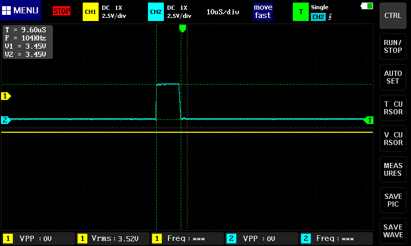
}이렇게 초음파가 제대로 생성되면
Echo 핀에서 거리에 따라 신호가 발생한다.
Input Capture
이 함수를 통해 Capture 한 CCR(Capture Compare Register) 값을 읽어 올 수 있다.
HAL_TIM_ReadCapturedValue(htim, TIM_CHANNEL_1);frequency(주파수) 계산을 할 때는 이 표를 봐야한다.
PCLK1 = APB1 peripheral Clock = 45MHz -> HAL_RCC_GetPCLK1Freq( )
PSC = Prescaler
관련 계산 코드
freq = (HAL_RCC_GetPCLK1Freq()*2)/(htim3.Instance->PSC + 1); // (45MHz*2) / 90 = 1MHz = 1,000,000 Hz
코드
코드에 대해 설명을 하자면
타이머가 신호에서 어떻게 자리 잡고 있는지 알아야한다.
RISING Edge
Rising Code 부분
/* Rising */
	if(htim->Instance == TIM3 && htim->Channel == HAL_TIM_ACTIVE_CHANNEL_1)
	{
		// Rising CCR 값 읽어오기
		risingCapture[risingCNT] = HAL_TIM_ReadCapturedValue(htim, TIM_CHANNEL_1);
		if(risingCNT == 1){
			risingCNT = 0;
			if(risingCapture[0] > risingCapture[1])
			{
				period = TIM3->ARR - risingCapture[0] + risingCapture[1];
                GPIOB->ODR |= LD3_Pin;
			}
			else
			{
				period = risingCapture[1] - risingCapture[0];
			}

			period += TIM3->ARR;	// 65535 + 34000 =>  sonar PSC 150 rising PSC 90
		}
		else
		{
			risingCNT = 1;
			GPIOB->ODR &= ~LD3_Pin;
		}
		GPIOB->ODR |= LD1_Pin;
		GPIOB->ODR &= ~LD2_Pin;

		freq = (HAL_RCC_GetPCLK1Freq()*2)/(htim3.Instance->PSC + 1);	// (45MHz*2) / 90 = 1MHz = 1,000,000 Hz
		freq = freq/period;
}if(risingCNT == 1)배열에 0, 1 인덱스를 넣는데
1일때 계산하니까 무조건 0 1 순서로 나열된다.
보통은 TIM3을 TIM4 보다 작은 주파수(긴 주기)로 Input Capture 하는 부분을 넓게 찍는데
1us 단위로 결과를 내고자
Prescaler를 작게 하여
16bits 최대 범위인 65535 의 Couter Period를 입력하여
약 15Hz 가 되었다.
그래서 아래와 같이 2개로 나눠졌는데
만약, 보통과 같이 TIM3 Hz < TIM4 Hz 로 했다면
위 if문만 빼고 사용하면 똑같다.
- 사진 누르면 커짐
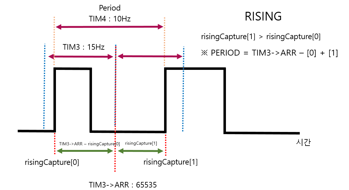
빨간색 점선이 구하고자 하는 Period 간격이다.
파란색 점선은 TIM3 의 간격이다.
노란색 점선은 TIM4 의 간격이다.
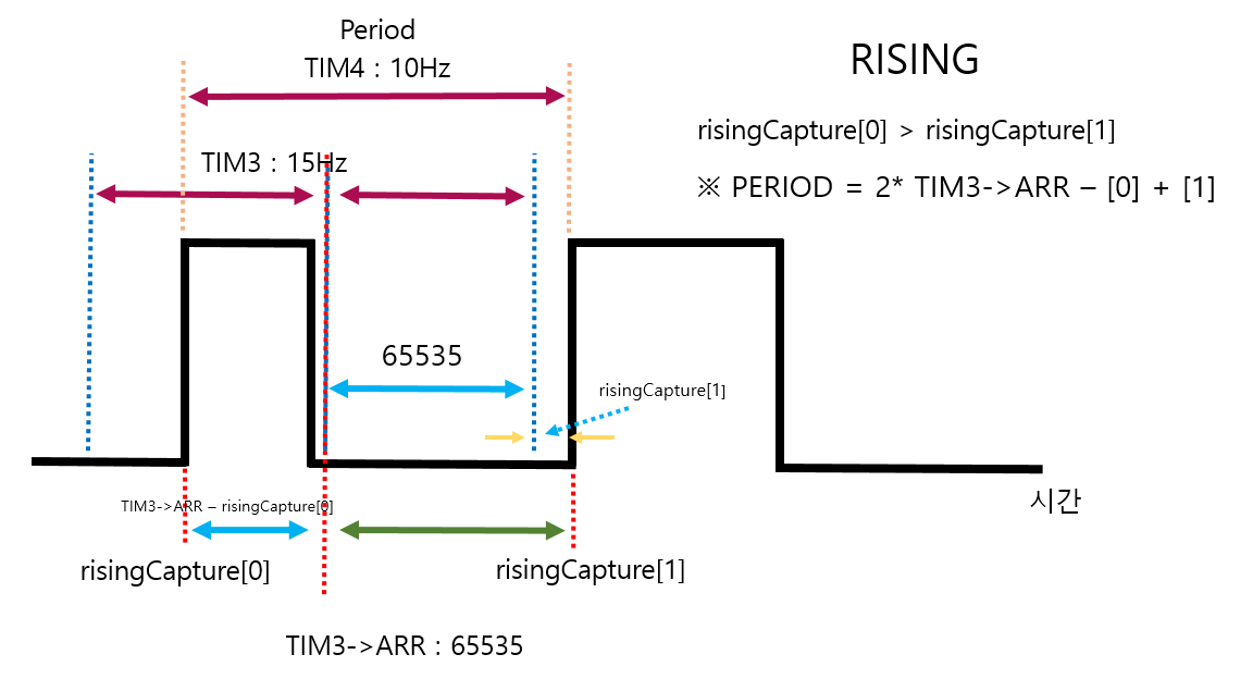
첫번째 if문에서 타이머3번의 channel_1 이 Rising 을 인식하면 활성화가 된다.
if(htim->Instance == TIM3 && htim->Channel == HAL_TIM_ACTIVE_CHANNEL_1)TIM3->ARR = 65535 의 겹치는 부분은 아래와 같이 처리했다.
period += TIM3->ARR; // 65535 + 34000 => sonar PSC 150 rising PSC 90주파수는 Timer 의 Counter Period 계산하듯 Prescaler 로 계산된 주파수를 Period 값으로 나누면된다.
freq = (HAL_RCC_GetPCLK1Freq()*2)/(htim3.Instance->PSC + 1);	// (45MHz*2) / 90 = 1MHz = 1,000,000 Hz
freq = freq/period;
FALLING Edge
/* Falling */
	if(htim->Instance == TIM3 && htim->Channel == HAL_TIM_ACTIVE_CHANNEL_2)
	{
    	// Falling CCR 값 읽어오기
		fallingCapture[fallingCNT] = HAL_TIM_ReadCapturedValue(htim, TIM_CHANNEL_2);
		if(fallingCNT == 1){
			fallingCNT = 0;
		}else{
			fallingCNT = 1;
		}

		if(fallingCapture[0] >= risingCapture[0] && fallingCapture[0] <= risingCapture[1])
		{
			width = fallingCapture[0] - risingCapture[0];

		}
		else if(fallingCapture[1] >= risingCapture[0] && fallingCapture[1] <= risingCapture[1])
		{
			width = fallingCapture[1] - risingCapture[0];
		}
		GPIOB->ODR &= ~LD1_Pin;
		GPIOB->ODR |= LD2_Pin;

		distance = width / 58;
		if(distance > 400) distance = 400;

		duty = width * 100/period;

	}
TIM3 의 channel_2에서 falling 을 Input Capture 했을 때 CCR 값을 저장한다.
fallingCapture[fallingCNT] = HAL_TIM_ReadCapturedValue(htim, TIM_CHANNEL_2);falling 과 rising이 교차했을 경우를 나눈 것이다.
자세히 보면 risingCapture[0] 과 risingCapture[1]은 바뀐게 없는데
fallingCapture[0]과 fallingCapture[1]만 바뀌었다.
한마디로 첫번째 rising을 검출하고 그 다음 falling 이 0이냐 1이냐 차이이다.
if(fallingCapture[0] >= risingCapture[0] && fallingCapture[0] <= risingCapture[1])
{
	width = fallingCapture[0] - risingCapture[0];
}
else if(fallingCapture[1] >= risingCapture[0] && fallingCapture[1] <= risingCapture[1])
{
	width = fallingCapture[1] - risingCapture[0];
}
Full Code
/* USER CODE END Header */
/* Includes ------------------------------------------------------------------*/
#include "main.h"
#include "tim.h"
#include "usart.h"
#include "gpio.h"

/* Private includes ----------------------------------------------------------*/
/* USER CODE BEGIN Includes */
#include "stdio.h"		// printf
#include "stdbool.h"	// true, false
/* USER CODE END Includes */

/* Private typedef -----------------------------------------------------------*/
/* USER CODE BEGIN PTD */

/* USER CODE END PTD */

/* Private define ------------------------------------------------------------*/
/* USER CODE BEGIN PD */
/* USER CODE END PD */

/* Private macro -------------------------------------------------------------*/
/* USER CODE BEGIN PM */

/* USER CODE END PM */

/* Private variables ---------------------------------------------------------*/

/* USER CODE BEGIN PV */
volatile uint16_t risingCapture[2];
volatile uint16_t fallingCapture[2];
uint8_t risingCNT = 0;
uint8_t fallingCNT = 0;
uint32_t period, freq, duty;
uint16_t width, distance;

// Printf 사용을 위한 더미 파일
struct __FILE {
    int dummy;
};
FILE __stdout;

/* USER CODE END PV */

/* Private function prototypes -----------------------------------------------*/
void SystemClock_Config(void);
/* USER CODE BEGIN PFP */

int fputc(int ch, FILE *f)
{
  HAL_UART_Transmit(&huart3, (uint8_t *)&ch, 1, 0xFFFF);

  return ch;
}
/* 마이크로세컨드 함수 선언 */
uint32_t DWT_Delay_Init(void);
void DWT_Delay_us(volatile uint32_t microseconds);
void TriggerEnable(void);

/* USER CODE END PFP */

/* Private user code ---------------------------------------------------------*/
/* USER CODE BEGIN 0 */

/* USER CODE END 0 */

/**
  * @brief  The application entry point.
  * @retval int
  */
int main(void)
{
  /* USER CODE BEGIN 1 */

  /* USER CODE END 1 */

  /* MCU Configuration--------------------------------------------------------*/

  /* Reset of all peripherals, Initializes the Flash interface and the Systick. */
  HAL_Init();

  /* USER CODE BEGIN Init */

  /* USER CODE END Init */

  /* Configure the system clock */
  SystemClock_Config();

  /* USER CODE BEGIN SysInit */

  /* USER CODE END SysInit */

  /* Initialize all configured peripherals */
  MX_GPIO_Init();
  MX_TIM3_Init();
  MX_TIM4_Init();
  MX_USART3_UART_Init();
  /* USER CODE BEGIN 2 */
	// timer, channel, array, quantity
	DWT_Delay_Init();
	// HAL_TIM_PeriodElapsedCallback
	HAL_TIM_Base_Start_IT(&htim4);

	// HAL_TIM_OC_DelayElapsedCallback
  	HAL_TIM_OC_Start_IT(&htim4, TIM_CHANNEL_1);		// create Sonar

	// HAL_TIM_IC_CaptureCallback
	HAL_TIM_IC_Start_IT(&htim3, TIM_CHANNEL_1);		// rising
	HAL_TIM_IC_Start_IT(&htim3, TIM_CHANNEL_2);		// falling

	printf("start the program\r\n");
	HAL_Delay(2000);
  /* USER CODE END 2 */

  /* Infinite loop */
  /* USER CODE BEGIN WHILE */
  while (1)
  {

		HAL_Delay(100);

		printf("[%5d, %5d]-%5d = %5d => Distance %4d cm| period : %6d | freq : %3d Hz| duty : %d %%\r\n", risingCapture[0], risingCapture[1], fallingCapture[0], width ,distance, period , freq, duty);

    /* USER CODE END WHILE */

    /* USER CODE BEGIN 3 */
  }
  /* USER CODE END 3 */
}

/**
  * @brief System Clock Configuration
  * @retval None
  */
void SystemClock_Config(void)
{
  RCC_OscInitTypeDef RCC_OscInitStruct = {0};
  RCC_ClkInitTypeDef RCC_ClkInitStruct = {0};

  /** Configure the main internal regulator output voltage
  */
  __HAL_RCC_PWR_CLK_ENABLE();
  __HAL_PWR_VOLTAGESCALING_CONFIG(PWR_REGULATOR_VOLTAGE_SCALE1);
  /** Initializes the RCC Oscillators according to the specified parameters
  * in the RCC_OscInitTypeDef structure.
  */
  RCC_OscInitStruct.OscillatorType = RCC_OSCILLATORTYPE_HSE;
  RCC_OscInitStruct.HSEState = RCC_HSE_BYPASS;
  RCC_OscInitStruct.PLL.PLLState = RCC_PLL_ON;
  RCC_OscInitStruct.PLL.PLLSource = RCC_PLLSOURCE_HSE;
  RCC_OscInitStruct.PLL.PLLM = 4;
  RCC_OscInitStruct.PLL.PLLN = 180;
  RCC_OscInitStruct.PLL.PLLP = RCC_PLLP_DIV2;
  RCC_OscInitStruct.PLL.PLLQ = 4;
  if (HAL_RCC_OscConfig(&RCC_OscInitStruct) != HAL_OK)
  {
    Error_Handler();
  }
  /** Activate the Over-Drive mode
  */
  if (HAL_PWREx_EnableOverDrive() != HAL_OK)
  {
    Error_Handler();
  }
  /** Initializes the CPU, AHB and APB buses clocks
  */
  RCC_ClkInitStruct.ClockType = RCC_CLOCKTYPE_HCLK|RCC_CLOCKTYPE_SYSCLK
                              |RCC_CLOCKTYPE_PCLK1|RCC_CLOCKTYPE_PCLK2;
  RCC_ClkInitStruct.SYSCLKSource = RCC_SYSCLKSOURCE_PLLCLK;
  RCC_ClkInitStruct.AHBCLKDivider = RCC_SYSCLK_DIV1;
  RCC_ClkInitStruct.APB1CLKDivider = RCC_HCLK_DIV4;
  RCC_ClkInitStruct.APB2CLKDivider = RCC_HCLK_DIV2;

  if (HAL_RCC_ClockConfig(&RCC_ClkInitStruct, FLASH_LATENCY_5) != HAL_OK)
  {
    Error_Handler();
  }
}

/* USER CODE BEGIN 4 */


/* Trigger 핀 활성화 */
void HAL_TIM_PeriodElapsedCallback(TIM_HandleTypeDef *htim)
{
	if(htim->Instance == TIM4)
	{
		GPIOB->ODR |= 0x01 << 6;  // PB 6 SET
	}
}

/* Trigger 핀 비활성화 */
void HAL_TIM_OC_DelayElapsedCallback(TIM_HandleTypeDef *htim)
{
	if(htim->Instance == TIM4)
	{
		GPIOB->ODR &= ~(0x01 << 6);	// PB 6	RESET, Pulse
	}
}


/* Input Capture 시 활성화 */
void HAL_TIM_IC_CaptureCallback(TIM_HandleTypeDef *htim)
{

	/* Rising */
	if(htim->Instance == TIM3 && htim->Channel == HAL_TIM_ACTIVE_CHANNEL_1)
	{
		// Rising CCR 값 읽어오기
		risingCapture[risingCNT] = HAL_TIM_ReadCapturedValue(htim, TIM_CHANNEL_1);
		if(risingCNT == 1){
			risingCNT = 0;
			if(risingCapture[0] > risingCapture[1])
			{
				period = TIM3->ARR - risingCapture[0] + risingCapture[1];
                GPIOB->ODR |= LD3_Pin;
			}
			else
			{
				period = risingCapture[1] - risingCapture[0];
			}

			period += TIM3->ARR;	// 65535 + 34000 =>  sonar PSC 150 rising PSC 90
		}
		else
		{
			risingCNT = 1;
			GPIOB->ODR &= ~LD3_Pin;
		}
		GPIOB->ODR |= LD1_Pin;
		GPIOB->ODR &= ~LD2_Pin;

		freq = (HAL_RCC_GetPCLK1Freq()*2)/(htim3.Instance->PSC + 1);	// (45MHz*2) / 90 = 1MHz = 1,000,000 Hz
		freq = freq/period;


	}

	/* Falling */
	if(htim->Instance == TIM3 && htim->Channel == HAL_TIM_ACTIVE_CHANNEL_2)
	{
    	// Falling CCR 값 읽어오기
		fallingCapture[fallingCNT] = HAL_TIM_ReadCapturedValue(htim, TIM_CHANNEL_2);
		if(fallingCNT == 1){
			fallingCNT = 0;
		}else{
			fallingCNT = 1;
		}

		if(fallingCapture[0] >= risingCapture[0] && fallingCapture[0] <= risingCapture[1])
		{
			width = fallingCapture[0] - risingCapture[0];

		}
		else if(fallingCapture[1] >= risingCapture[0] && fallingCapture[1] <= risingCapture[1])
		{
			width = fallingCapture[1] - risingCapture[0];
		}
		GPIOB->ODR &= ~LD1_Pin;
		GPIOB->ODR |= LD2_Pin;

		distance = width / 58;
		if(distance > 400) distance = 400;

		duty = width * 100/period;

	}
}


uint32_t DWT_Delay_Init(void)
{
  /* Disable TRC */
  CoreDebug->DEMCR &= ~CoreDebug_DEMCR_TRCENA_Msk; // ~0x01000000;
  /* Enable TRC */
  CoreDebug->DEMCR |=  CoreDebug_DEMCR_TRCENA_Msk; // 0x01000000;

  /* Disable clock cycle counter */
  DWT->CTRL &= ~DWT_CTRL_CYCCNTENA_Msk; //~0x00000001;
  /* Enable  clock cycle counter */
  DWT->CTRL |=  DWT_CTRL_CYCCNTENA_Msk; //0x00000001;

  /* Reset the clock cycle counter value */
  DWT->CYCCNT = 0;

     /* 3 NO OPERATION instructions */
     __ASM volatile ("NOP");
     __ASM volatile ("NOP");
  __ASM volatile ("NOP");

  /* Check if clock cycle counter has started */
     if(DWT->CYCCNT)
     {
       return 0; /*clock cycle counter started*/
     }
     else
  {
    return 1; /*clock cycle counter not started*/
  }
}

void DWT_Delay_us(volatile uint32_t microseconds)
{
  uint32_t clk_cycle_start = DWT->CYCCNT;

  /* Go to number of cycles for system */
  microseconds *= (HAL_RCC_GetHCLKFreq() / 1000000);

  /* Delay till end */
  while ((DWT->CYCCNT - clk_cycle_start) < microseconds);
}

void TriggerEnable(void)
{
	GPIOB->ODR &= ~TRIGGER_Pin;	// initialize
	DWT_Delay_us(2);
	GPIOB->ODR |= TRIGGER_Pin;	// Trigger signal
	DWT_Delay_us(11);
	GPIOB->ODR &= ~TRIGGER_Pin;	// shut down
}

/* USER CODE END 4 */

/**
  * @brief  This function is executed in case of error occurrence.
  * @retval None
  */
void Error_Handler(void)
{
  /* USER CODE BEGIN Error_Handler_Debug */
  /* User can add his own implementation to report the HAL error return state */
  __disable_irq();
  while (1)
  {
  }
  /* USER CODE END Error_Handler_Debug */
}

#ifdef  USE_FULL_ASSERT
/**
  * @brief  Reports the name of the source file and the source line number
  *         where the assert_param error has occurred.
  * @param  file: pointer to the source file name
  * @param  line: assert_param error line source number
  * @retval None
  */
void assert_failed(uint8_t *file, uint32_t line)
{
  /* USER CODE BEGIN 6 */
  /* User can add his own implementation to report the file name and line number,
     ex: printf("Wrong parameters value: file %s on line %d\r\n", file, line) */
  /* USER CODE END 6 */
}
#endif /* USE_FULL_ASSERT */