Digital System
Digital circuit = Logic circuit
Digital System
discrete or seperate over time
Analog System
continuous over time
3-1 Boolean Constants and Variables
Boolean algebra allows only two values → 0 and 1
| Logic 0 | Logic 1 |
|---|---|
| False | True |
| Off | On |
| LOW | HIGH |
| No | Yes |
| Open switch | Closed switch |
3-2 Truth Tables
A truth table describes the relationship between the input and output of a logic circuit.
The number of entries corresponds to the number of inputs.
- A 2-input table would have 2^2 = 4 entries.
- A 3-input table would have 2^3 = 8 entries.
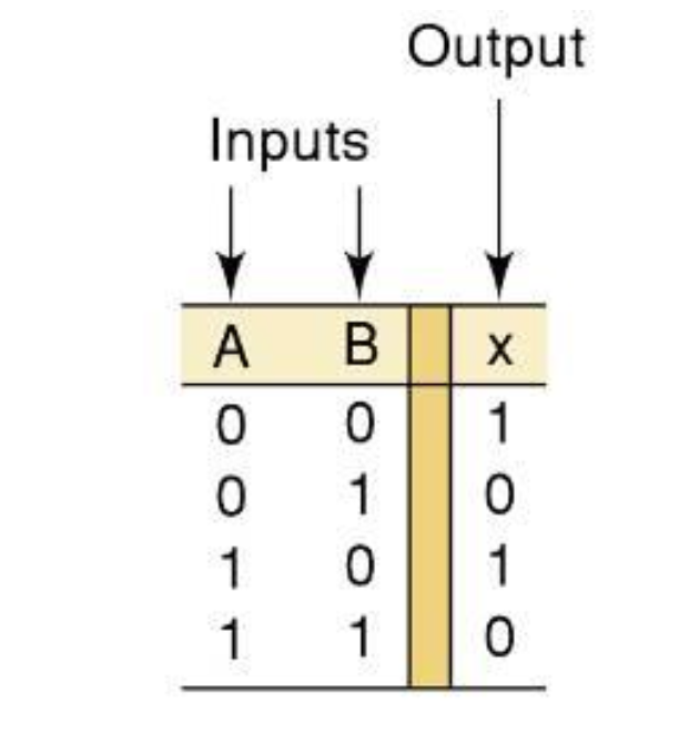
3-3 OR Operation With OR Gates
+ = "OR"

1 + 1 = 1
→ OR은 하나라도 1이면 결과가 1인 연산이다.

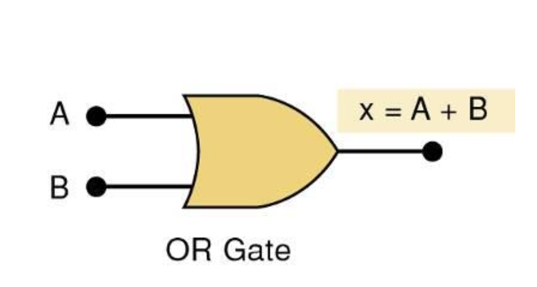
OR Gate
OR Gate is a circuit(Logic Circuit) with two or more inputs, whose output is equal to the OR combination of the inputs
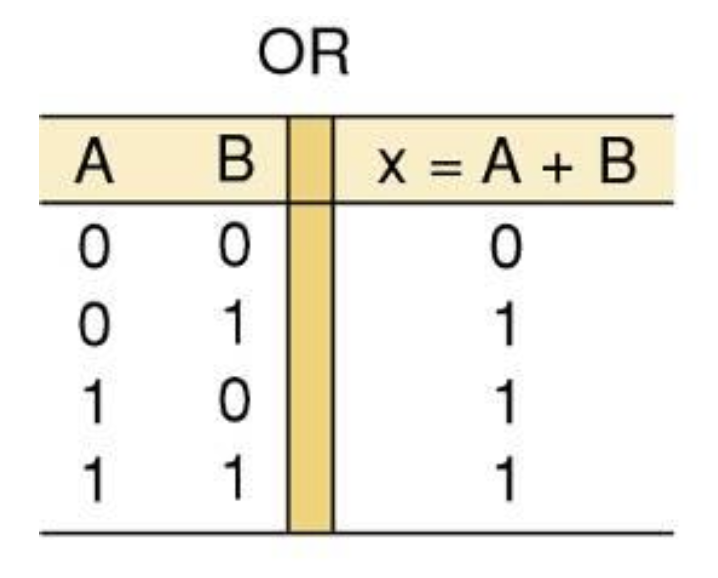
OR Truth table
Two input OR Gate Symbol
two input → all possible cases = 4
Three input OR Gate Symbol
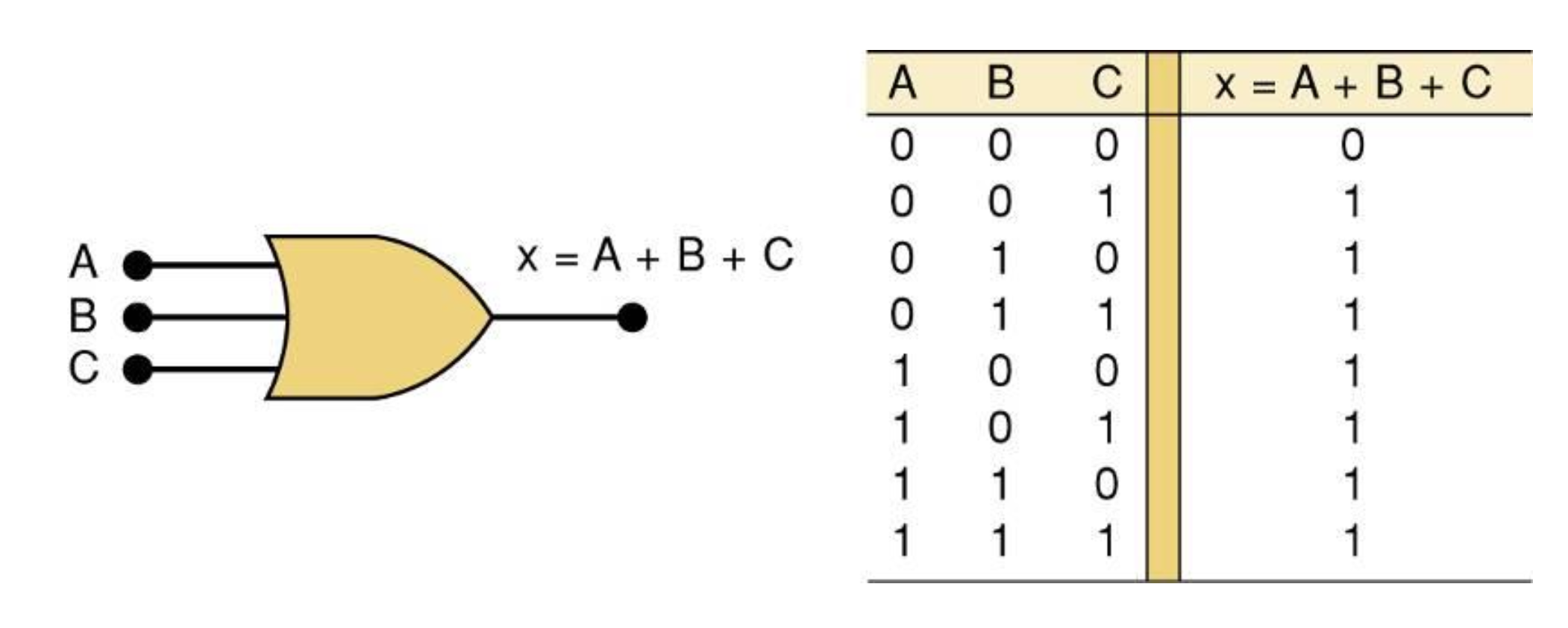
not popular
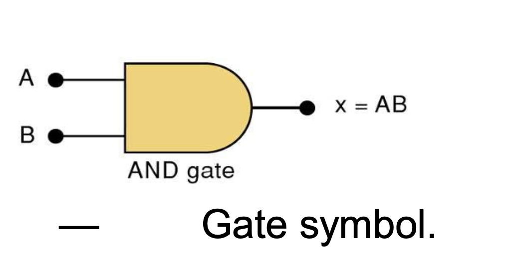
3-4 AND Operations with AND Gates
* = "AND"

→ 전부 1일(true) 때만 결과가 1이 나온다.
AND Truth table
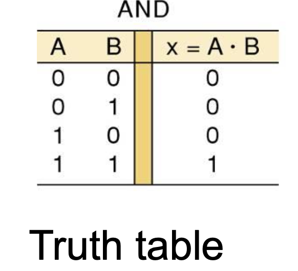
AND Gate Symbol
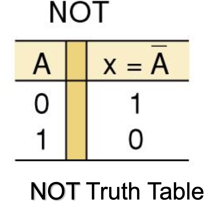
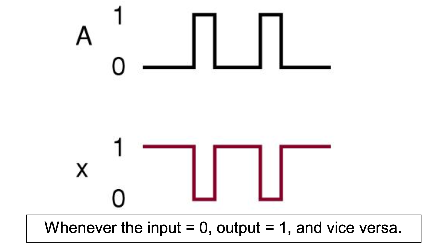
3-5 NOT Operation
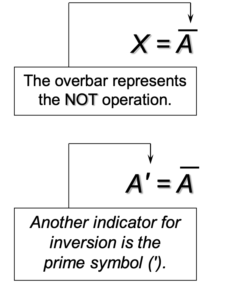
NOT A
= Bar A
= inverse of A
= complement(여집합) of A
NOT Truth Table
NOT Symbol

1 input → 1 output
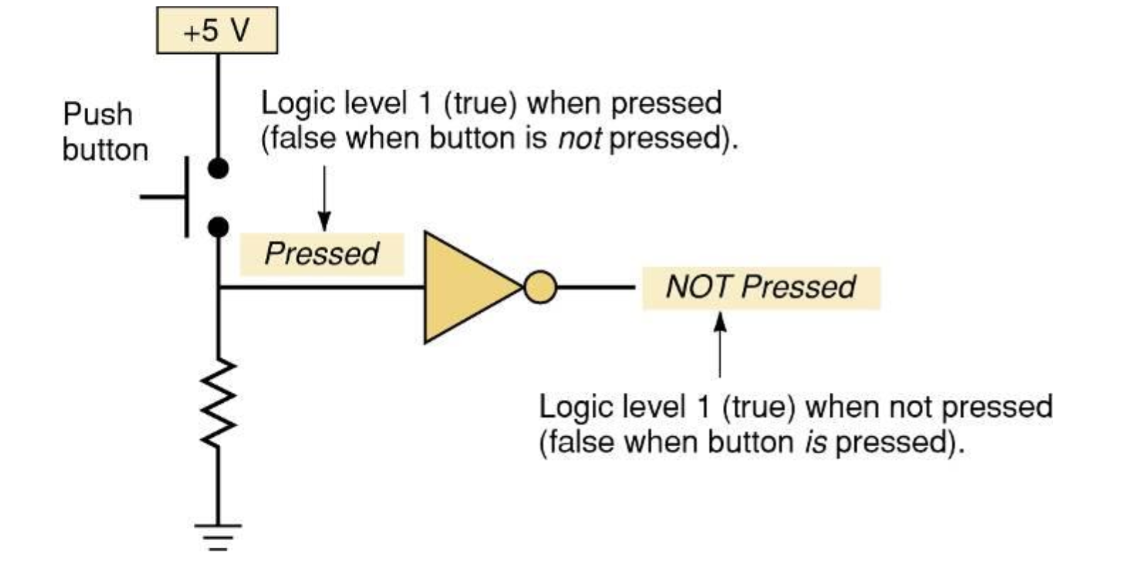
INVERTER
전형적인 NOT Gate
스위치가 눌리지 않은 상태 → 0 → NOT Gate → 1 = NOT Pressed
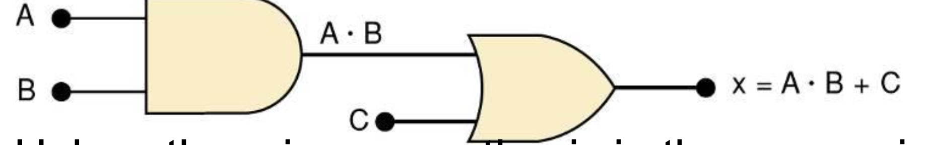
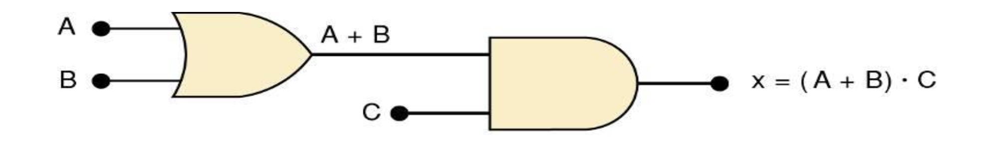
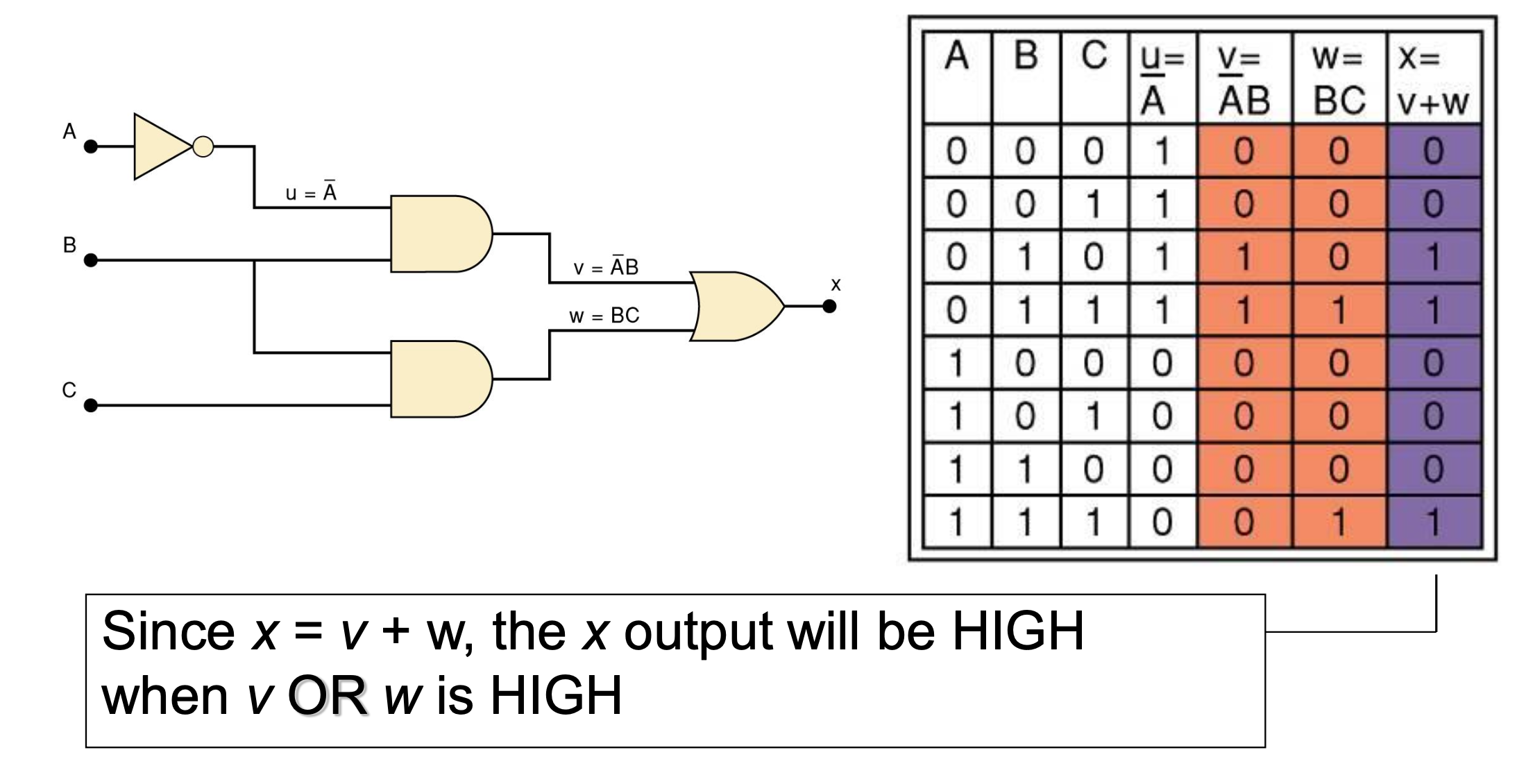
3-6 Describing Logic Circuit Algebraically
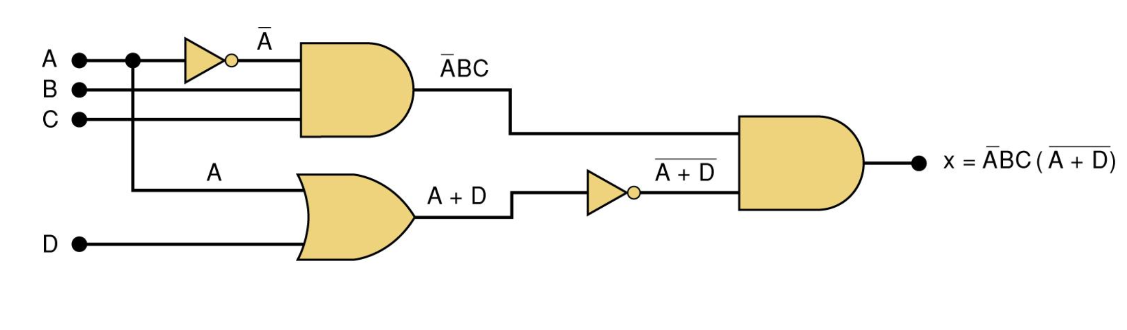
3-7 Evaluating Logic Circuit Outputs
Step 1
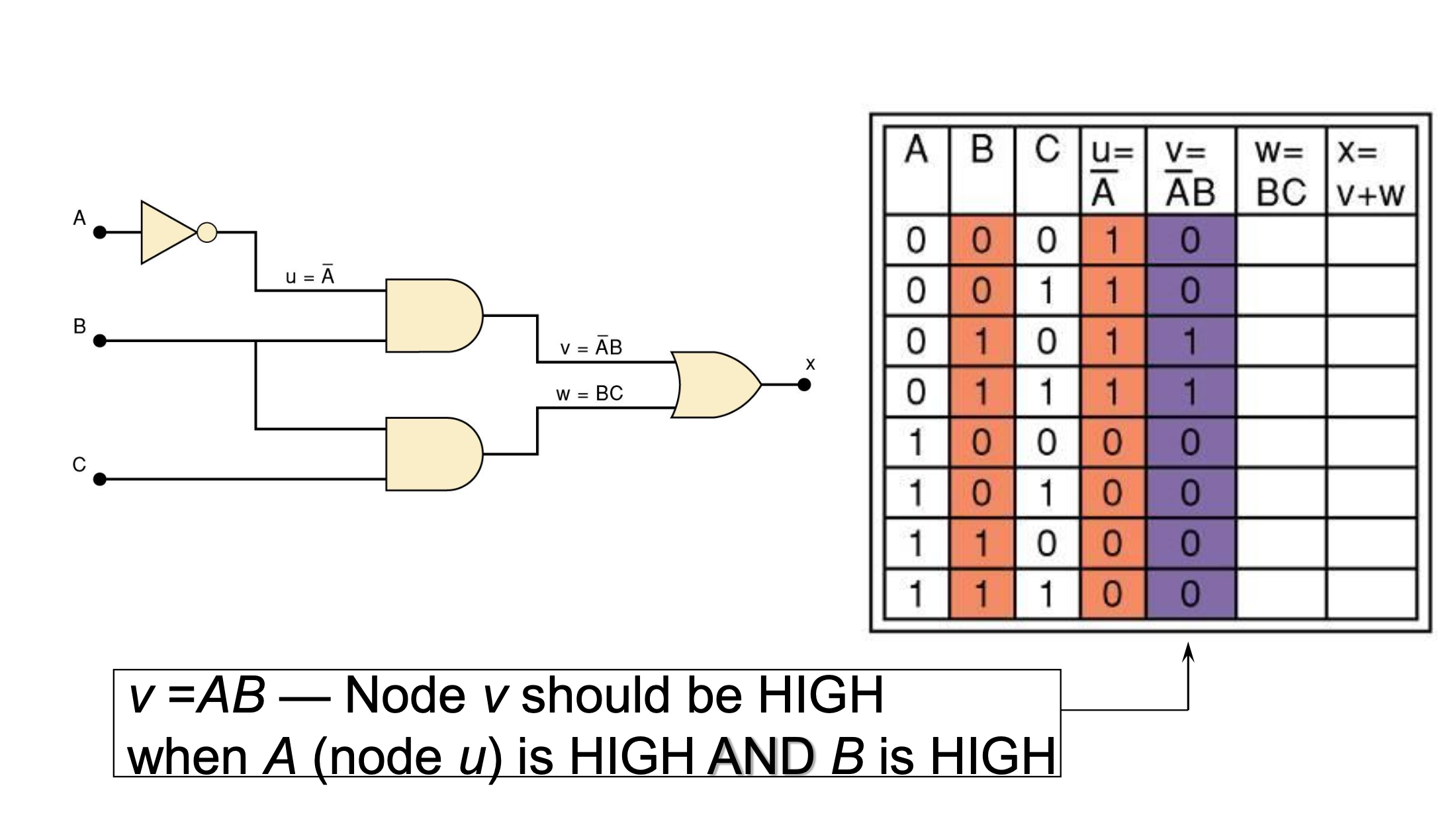
Step 2
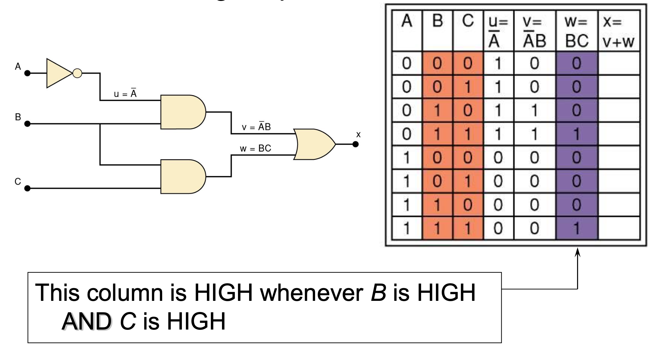
Step 3
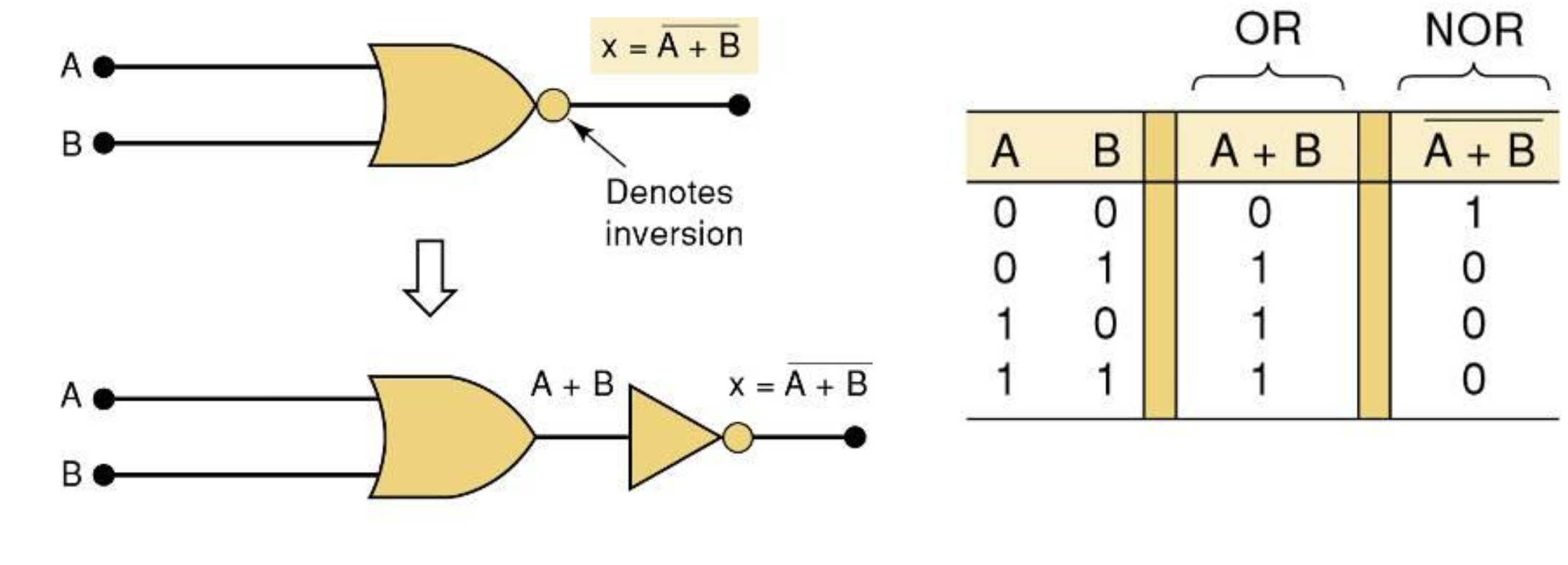
3-9 NOR Gates and NAND Gates
NOR Gate
OR 하고 NOT 하는 로직을 합친 게이트
NAND Gate
AND 하고 NOT 하는 로직을 합친 게이트

3-10 Boolean Theorems
AND
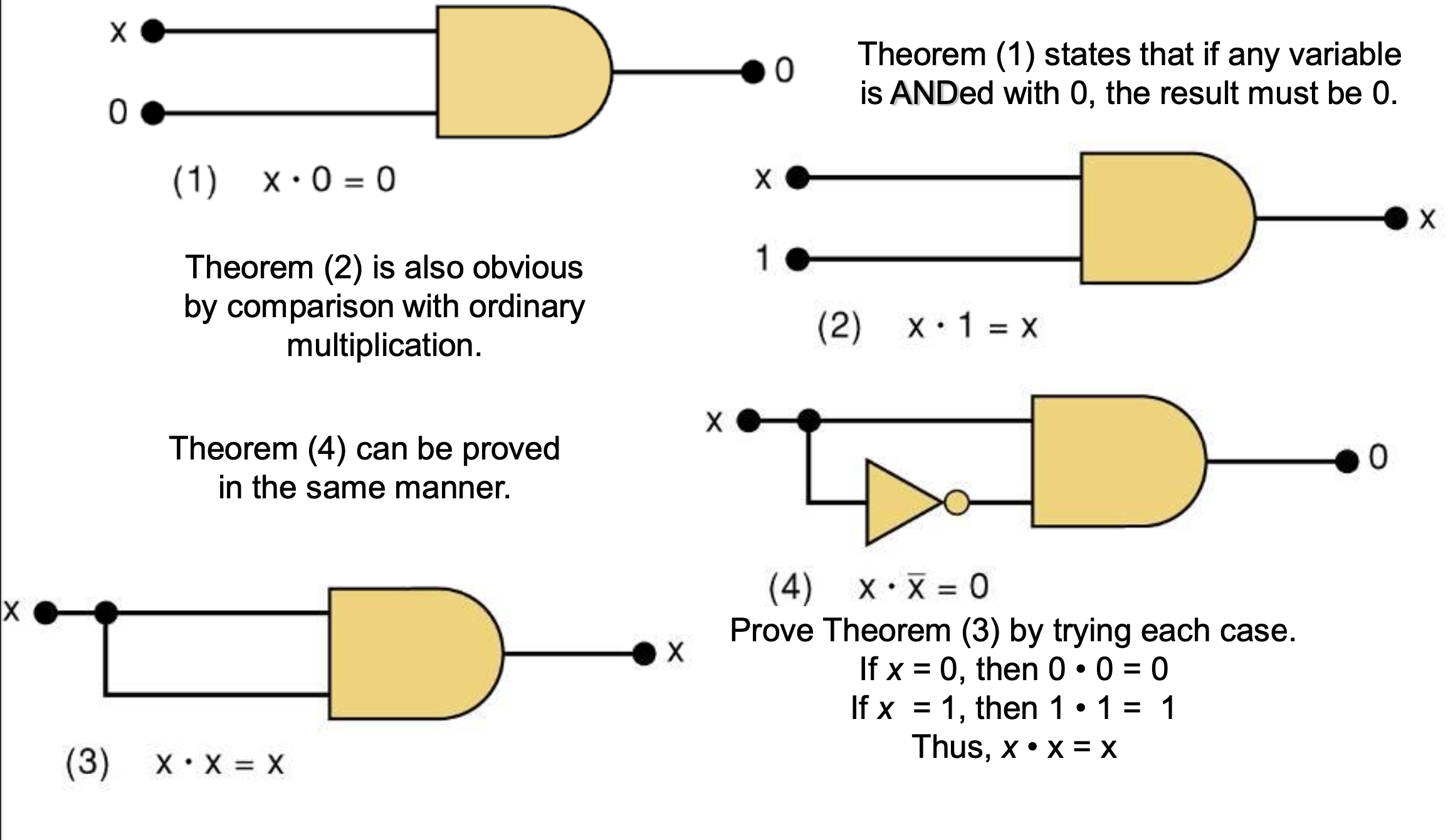
1. X*0 = 0
2. X*1 = X
3. X*X = X
4. X*!X = 0
OR
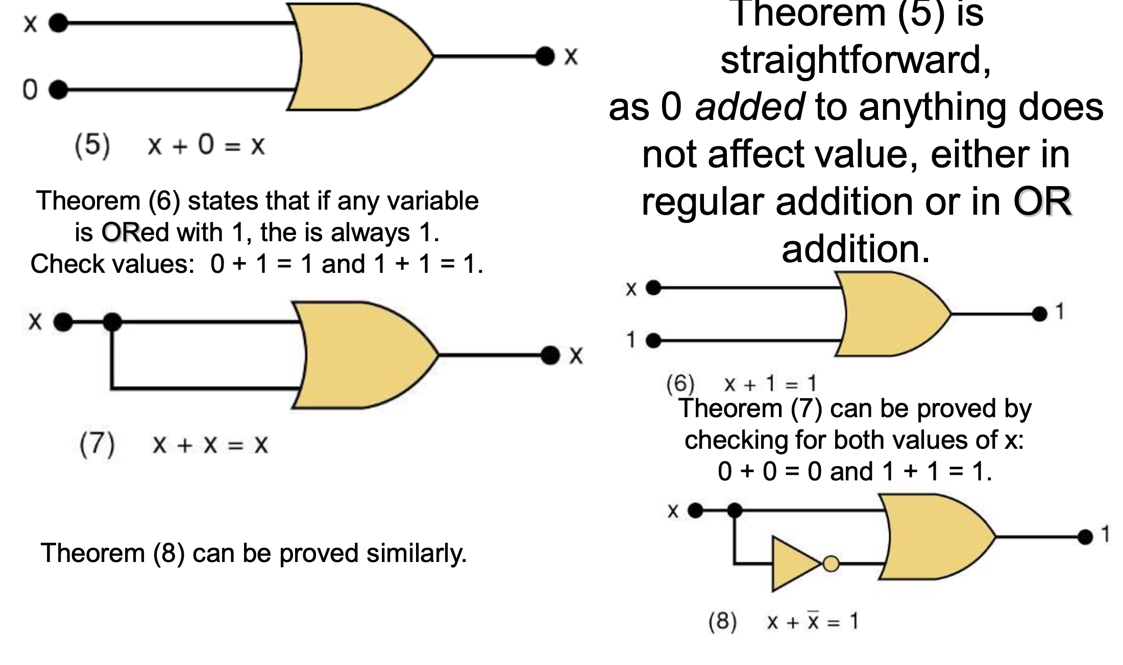
5. X + 0 = X
6. X + 1 = 1
7. X + X = X
8. X + !X = 1
Commutative laws
(교환법칙)
9. X + Y = Y + X
10. XY = YX
Associative laws
(결합법칙)
11. X + (Y + Z) = (X + Y) + Z = X + Y + Z
12. X(YZ) = (XY)Z = XYZ
Distributive law
(분배법칙)
13a. X(Y + Z) = XY + XZ
13b. (W + X)(Y + Z) = WY + XY + WZ + XZ
14. X + XY = X
X(1 + Y) = X*1 = X
15a. X + !XY = X + Y
15B. !X + XY = !X + Y
| input | output | |
|---|---|---|
| x+y | high | high |
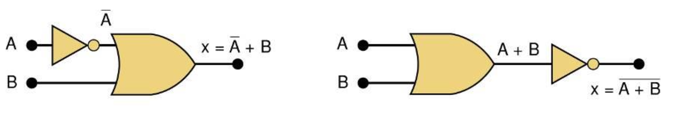
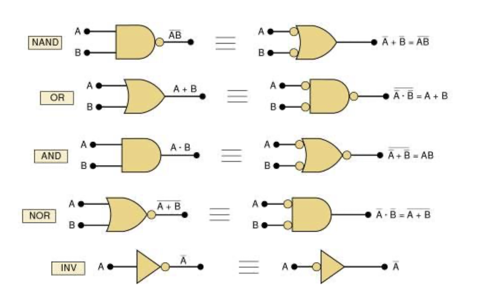
3-11 DeMorgan's Theorems
16. !(X + Y) = !X*!Y

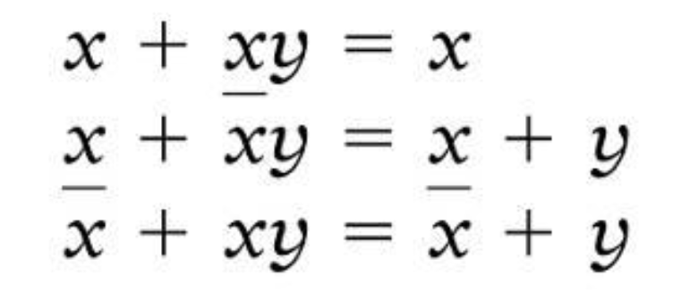
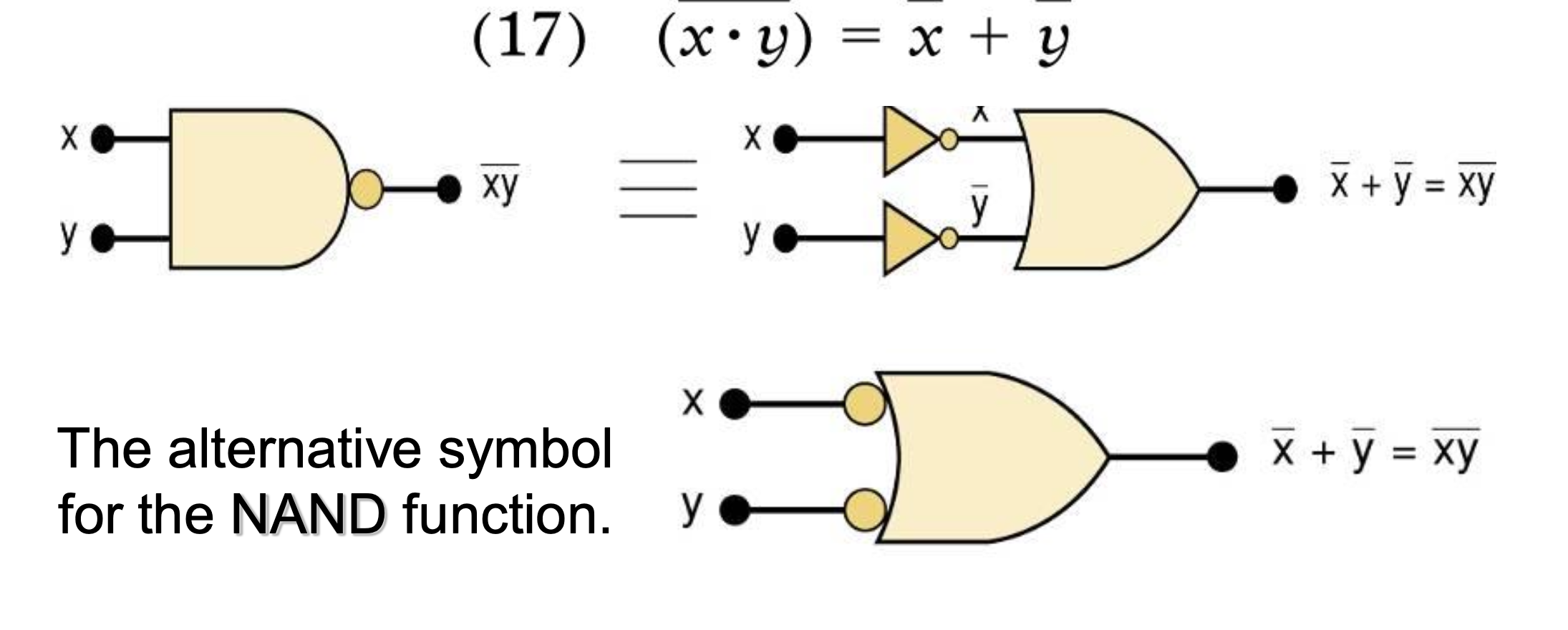
17. !(X*Y) = !X + !Y
두 게이트는 서로 생김새가 다르지만, 결과값은 동일하다.
단, 관점이 다르다.
- 왼쪽 게이트: 언제 0이 되지?
- 오른쪽 게이트: 언제 1(high)가 되지?
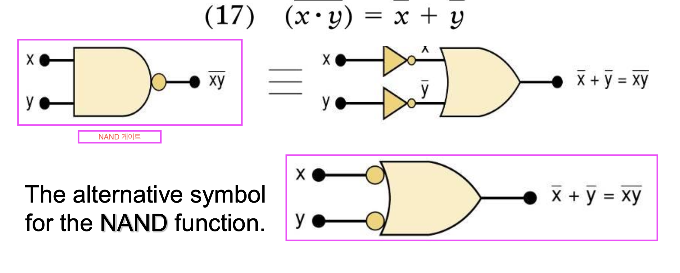
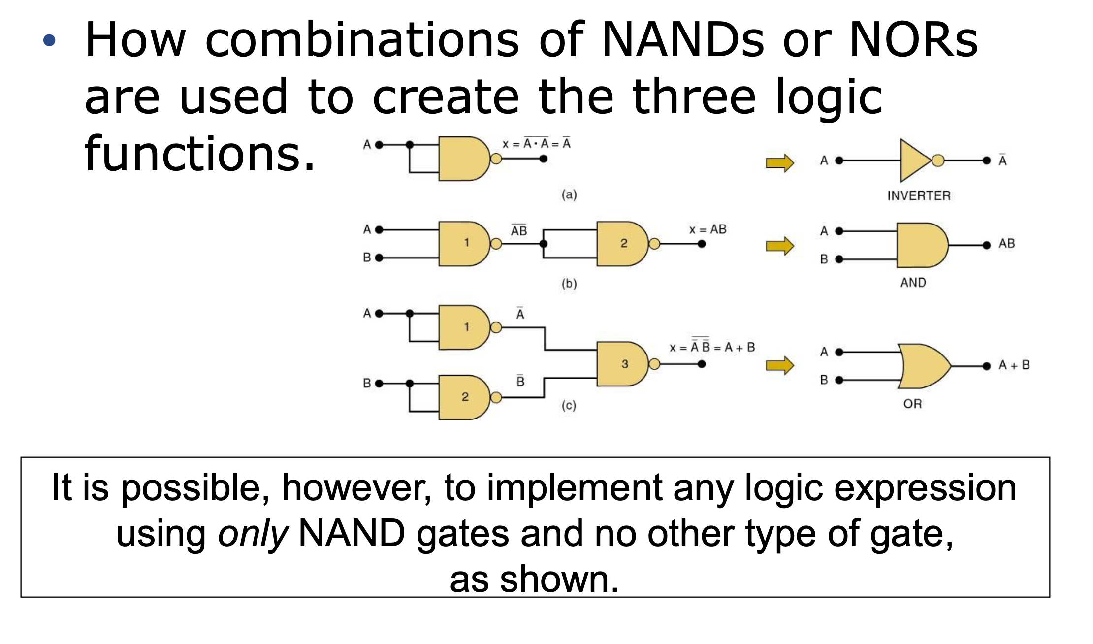
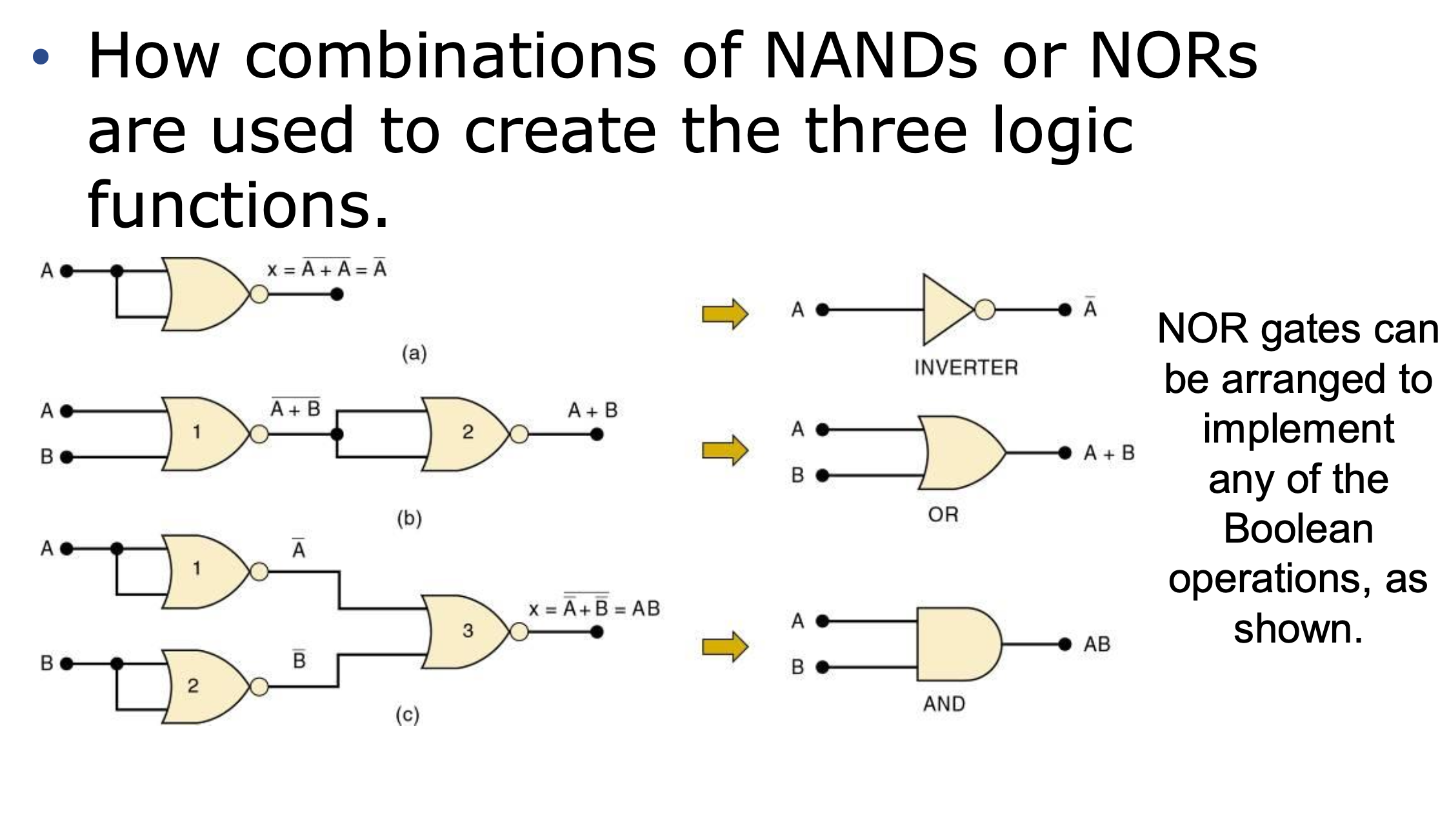
3-12 Universality of NAND and NOR Gates
Basic three gate
→ OR, AND, NOT(INVERT)
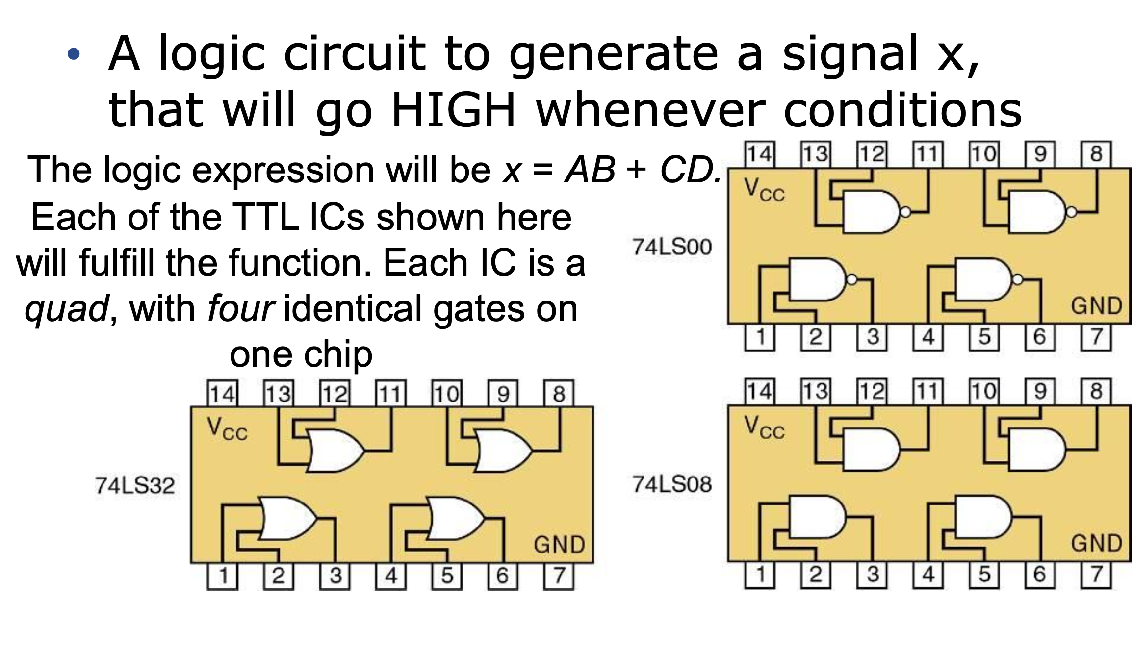
조건이 뭐든간에 항상 결과가 HIGH인 logic circuit
Possible Implementations # 1 ??
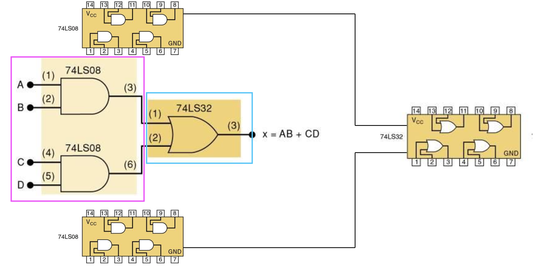
- Gate: 3개 사용
- Chip(IC Chip): 2개 사용
Possible Implementations #2 ??
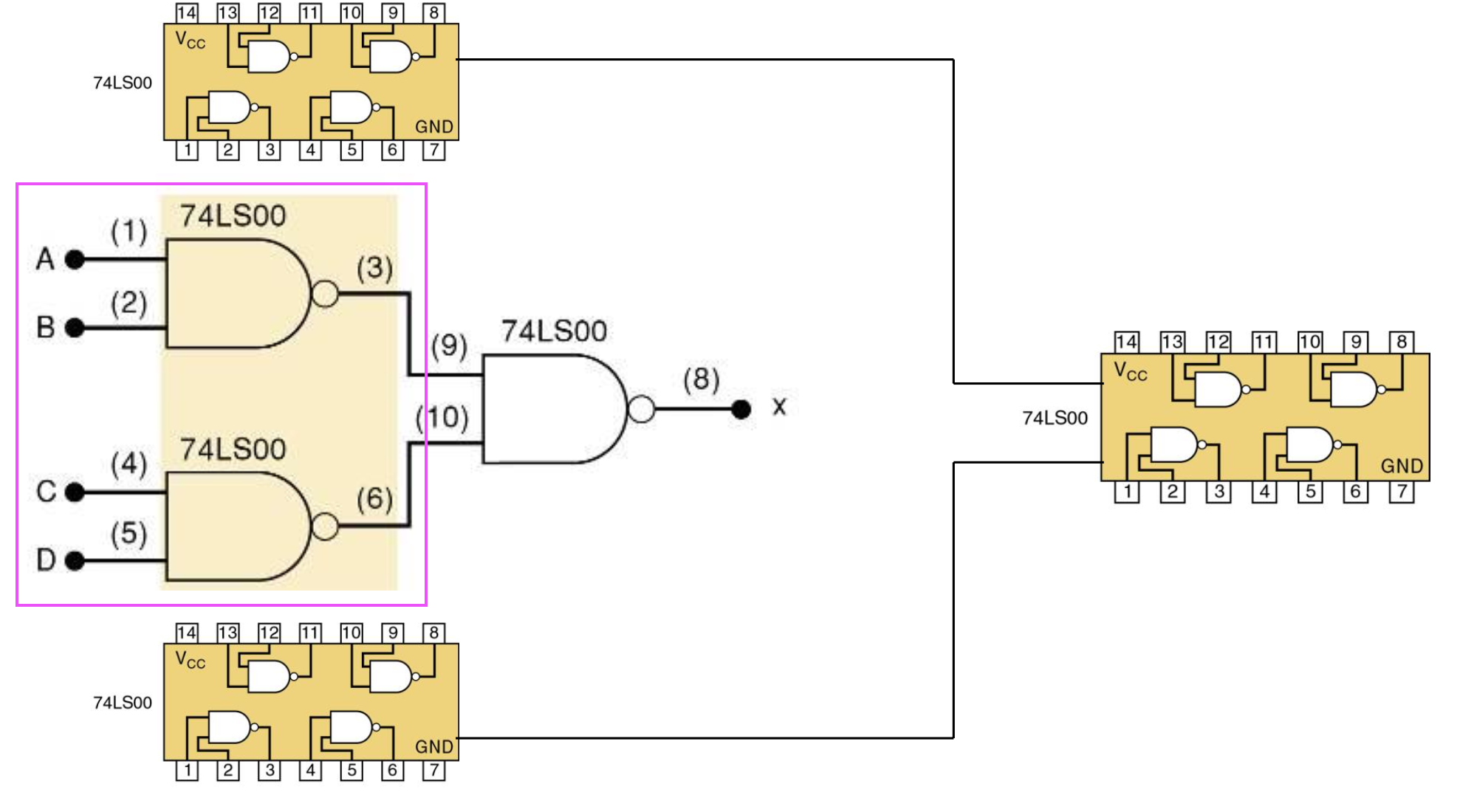
- Gate: 4개 사용
- Chip(IC Chip): 1개 사용
3-13 Alternate Logic-Gate Represetation
-
Bubble은Non-gate를 가르킨다. -
AND와OR게이트는 버블 반대로 하면 같은 게이트가 된다.
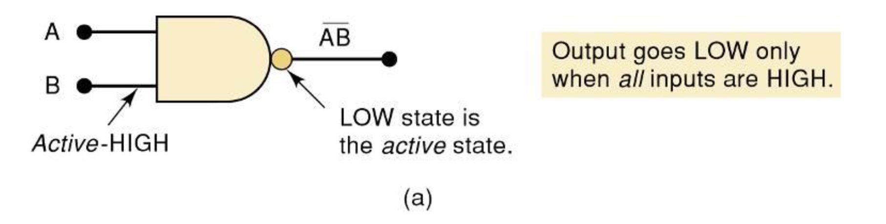
Active-HIGH
an input/output has no inversion bubble.
버블이 둘 다 붙어있지 않은 게이트
Active-LOW
an input or output has an inversion bubble.
버블이 둘 다 붙어있는 게이트
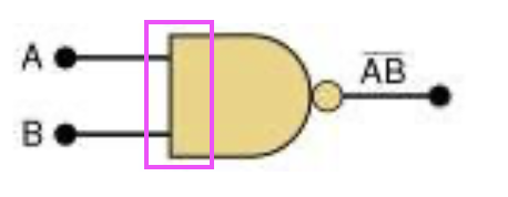
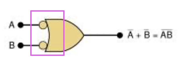
두 NAND Gate symbol의 해석 차이
NAND Gate
Output goes LOW only when all inputs are HIGH.
오직 모든 입력이 High 일 때만, 결과가 LOW가 된다.
Output will be HIGH when any input will go LOW.
입력에 LOW가 있기만 해도 출력은 항상 HIGH 이다.
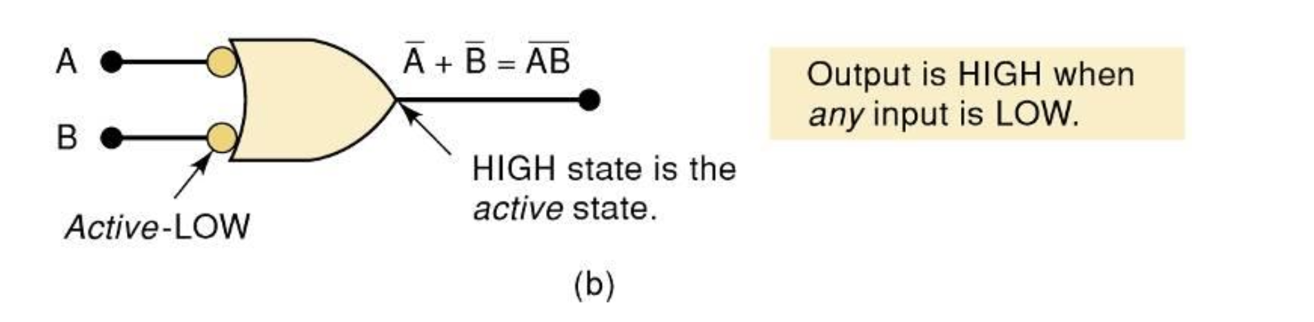
⇒ !A + !B = !(AB)
두 OR Gate symbol의 해석 차이
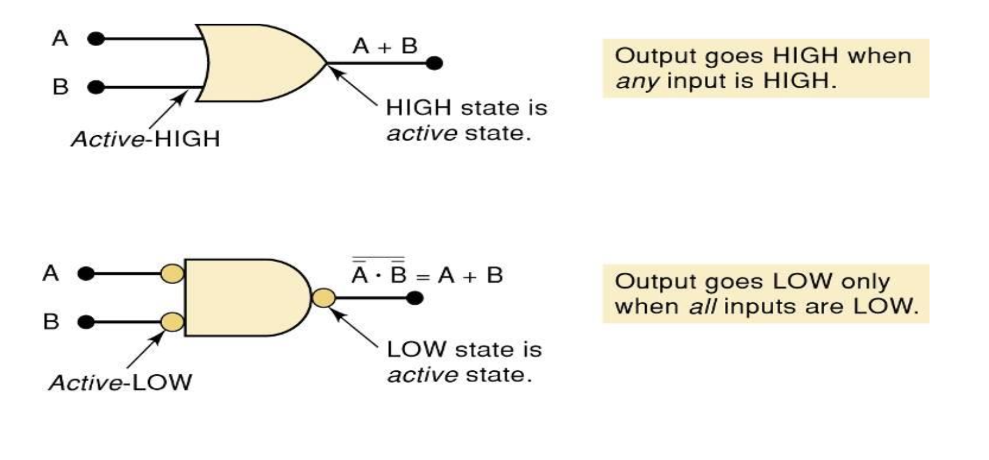
⇒ A + B = !(!A * !B)
5 Gates
- OR
- AND
- NOT
- NOR
- NAND
Alternatice Symbols
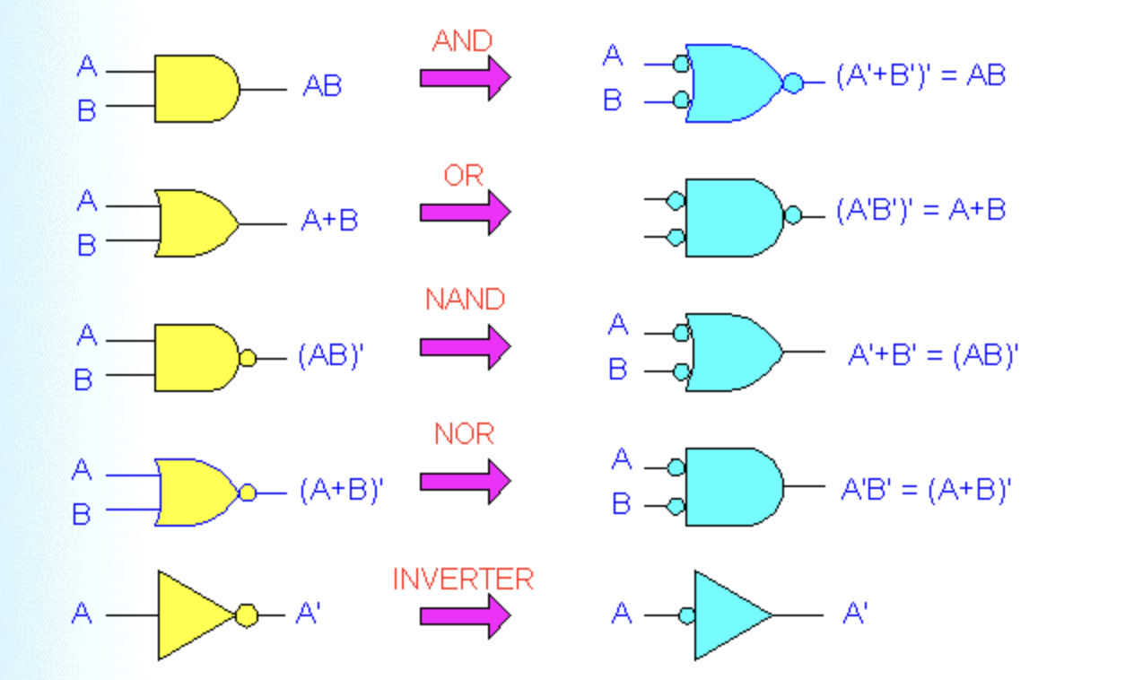
-
마지막 NOT Gate의 INVERTER 버전은 거의 사용되지 않는다.
-
Bubble을 지우는 방법 ⇒ Alternative Symbol
IC = Intergrate Chip
3-14 Which Gate Representation to Use(중요)
Circuit diagram에서 적절한 alternative gate symbol을 사용하는 것은 Circuit operation을 훨씬 더 쉽게 사용할 수 있게해준다.
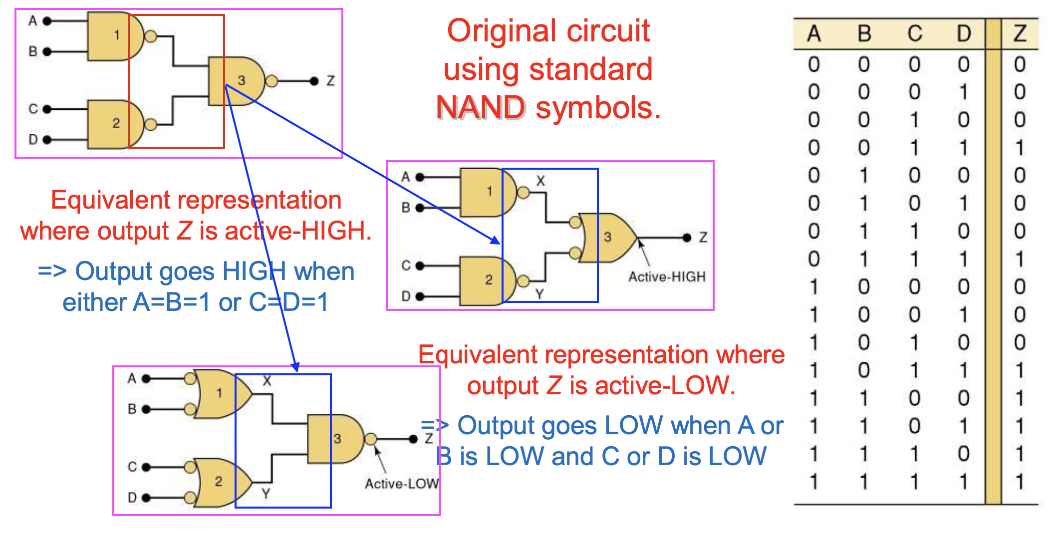
붙어있는 output과 input에 버블이 둘 다 있거나 없는 것이 좋다.
둘 다 있을 경우, 생략할 수 있다.
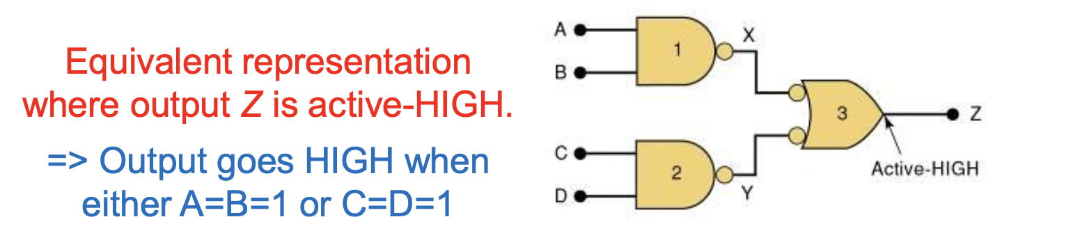
A=B=1 OR C=D=1 일 때, Output은 HIGH가 된다.
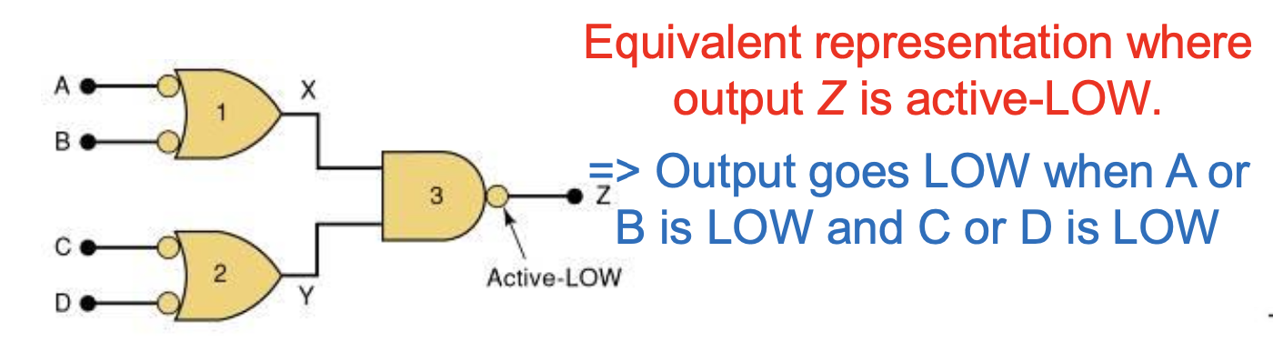
A OR B is LOW and C or D is LOW 일 때, Output은 LOW가 된다.
Logic Signal
Logic Signal이 active state(HIGH or LOW)라면 asserted(강조) 되었다고 한다.
Logic Signal이 inactive state(HIGH or LOW)라면 unasserted 되었다고 한다.
-
bar가 붙으면,
(active) LOW라고 강조된다.
-
bar가 붙지 않으면,
(activate) HIGH라고 강조된다.

가능하다면, bubble outputs은 bubble input이랑 연결되는 gate symbol을 골라라.
Nonbubble output은 nonbubble input이랑 연결되는 게 좋음.
알람 logic circuit
밑의 logic circuit은 Z가 HIGH일 때, 활성화된다.
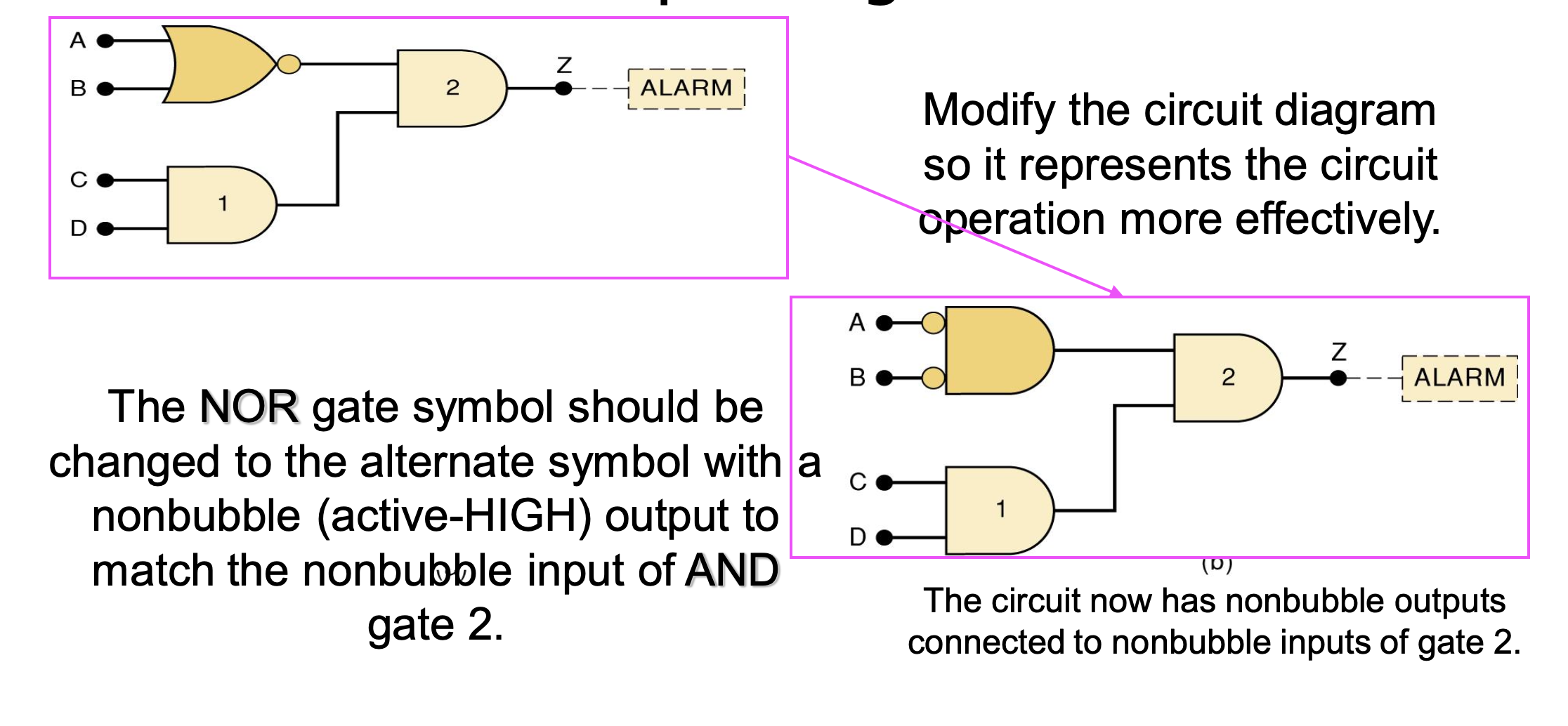
회로 다이어그램을 수정하여 회로 명령을 효율적으로 만들었다.
3-15 Propagation Delay
전파지연시간
Logic circuit의 속도는 Propagation Delay와 관련 있다.
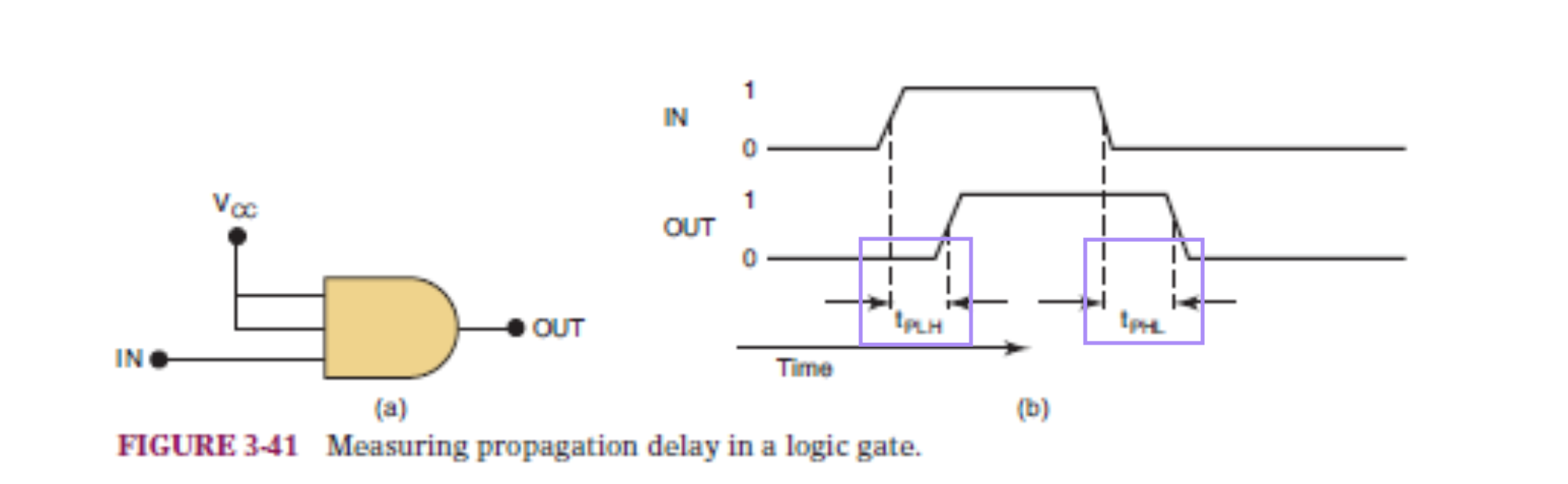
- tPLH = Propagation Low to High
- tPHL = Propagation High to Low
3-16 Summary of Methods To Describe Logic Circuits (중요)
다음을 사용하여 각각의 Basic Logic Functions을 표현한다.
- Logical Statememts in our own Language
- Truth tables
- Traditional graphic logic symbols
- Boolean algebra expressions
- Timing diagrams
3-17 Description vs.Programming Languages
HDL (Hardware Discription Languages)
HDL을 사용하면 엄격하게 정의된 언어로 논리 회로를 나타낼 수 있다.
AHDL (Altera Hardware Description Language)
- Altera에서 개발하여 Altera Programmable Logic Devices(PLD)를 구성한다.
- 논리 회로를 설명하기 위한 범용 언어로 사용하기 위한 것이 아니다.
VHDL (Very High Speed Integrated circuit Hardware Description Language)
- Developed by U.S. Department of Defense (DoD).
- Standardized by IEEE.
- 설계를 실제 장치를 프로그래밍하는 비트 패턴으로 변환하는 데 널리 사용된다.
HDL(Hardware Description Languages)와 Programming Language를 구별하는 것이 중요하다.
3-18 Implementing Logic Circuit With PLDs
PLD
Programmable Logic Devices (PLDs) 논리 기능을 수행하기 위해 다양한 방식으로 구성할 수 있는 장치이다.
→ 프로그램 장치에 대한 내부 연결이 전자적으로 이루어진다.
PLD는 전자적으로 구성되며 내부 회로는 전자적으로 함께 "wired"되어 논리 회로를 형성한다.
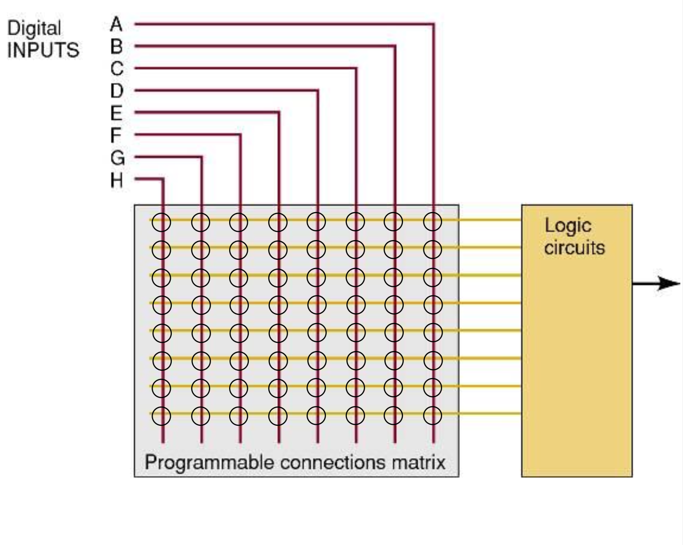
이 프로그래밍 가능한 배선은 연결되거나(1) 연결되지 않은(0) 수천 개의 연결로 생각할 수 있다.
행(수평 와이어) 및 열(수직 와이어)의 각 교차점은 프로그래밍 가능한 연결이다.
HDL은 만들 연결은 정의한다.
3-19 HDL Format and Syntax
컴퓨터들에 의해 해석되어진 언어들은 엄격한 syntax (구문) 규칙을 따라야한다.
syntax는 요소들의 순서를 나타낸다.