Computer Network
Chapter6 : Delivery and Forwarding of IP packets
6.1 Delivery
The network layer supervises delivery.
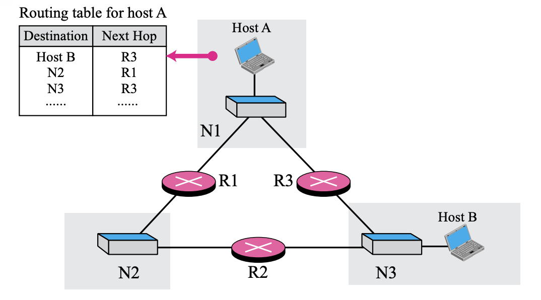
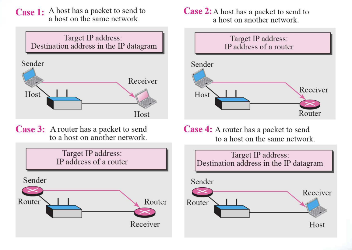
The Delivery of a packet to its final destination is accomplished using two different methods of delivery : Direct and Indirect
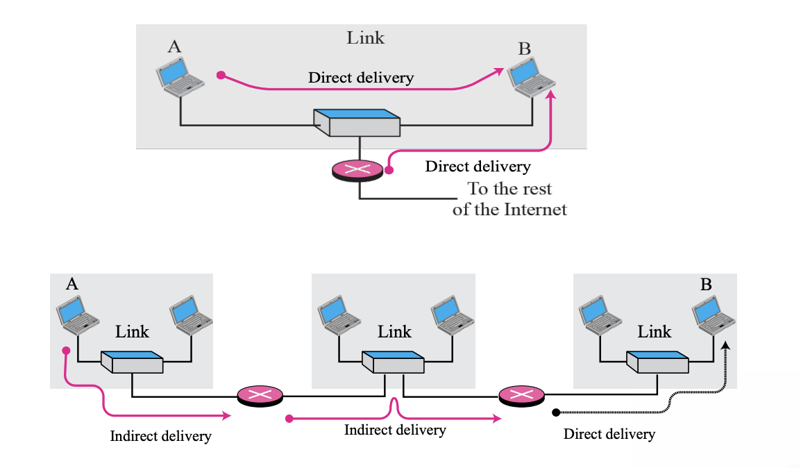
- Direct Delivery
- Hosts with final destinations connected to the same network
- Packets are located on the same network as their source and destination
- Performed between the final router and the destination host
- If NetID is extracted from the destination address and compared to the network address, it is directly Perform Forwarding
- Indirect Delivery
- Final destination is a host that is not on the same network
- Forward via multiple routers
- Use the routing table to find the IP address
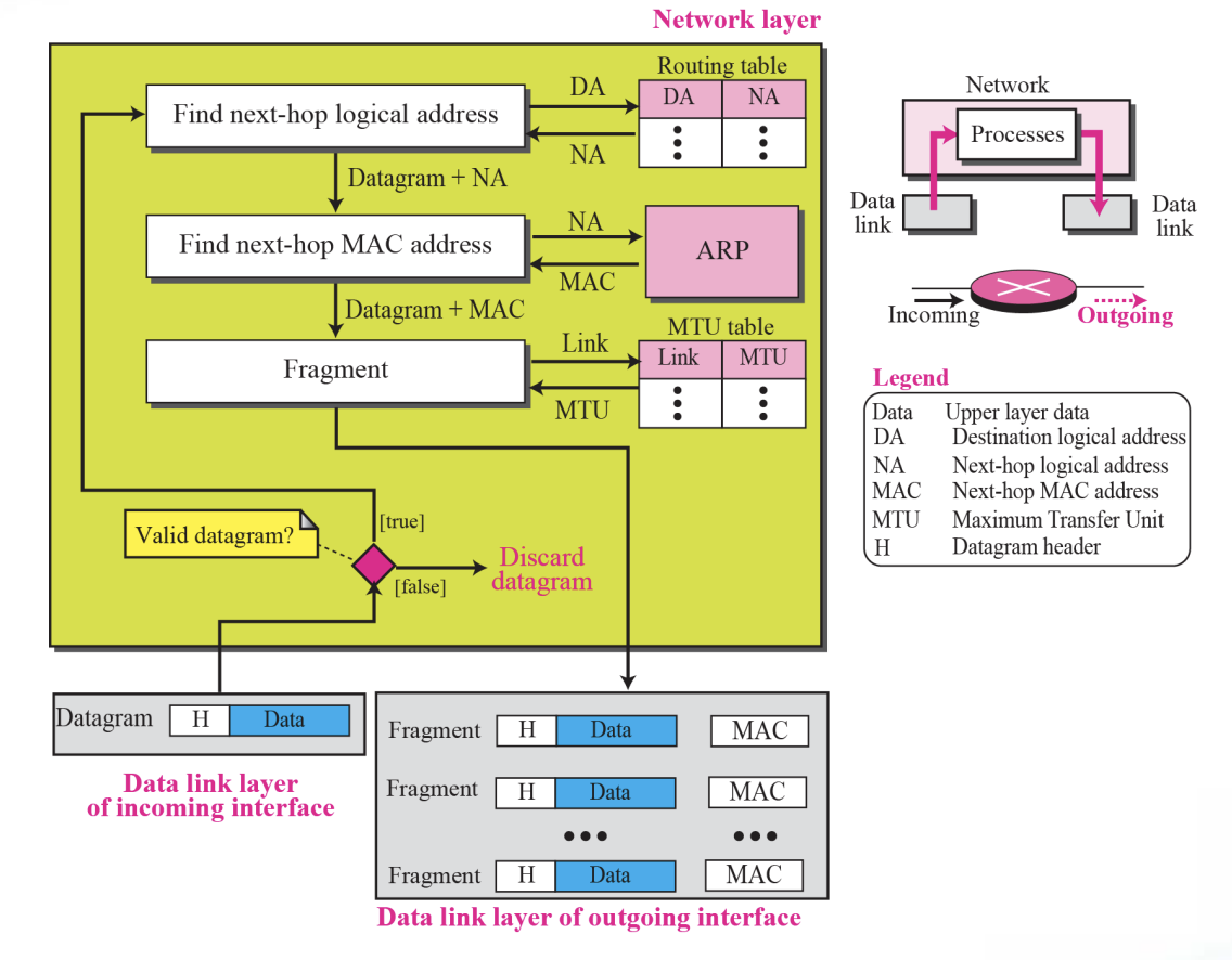
6.2 Forwarding
Forwarding means to place the packet in its route to its destination. Forwarding requires a host or a router to have a routing table.
- Today, simple solution(look up route at a table) is impossible today in an internetwork
- Several techniques can make the size of the routing table manageable and also handle issues such as security
Forwarding techniques
- Next-hop method
- Network-specific method
- Host-specific method
- Default method
6.3 Next-hop method
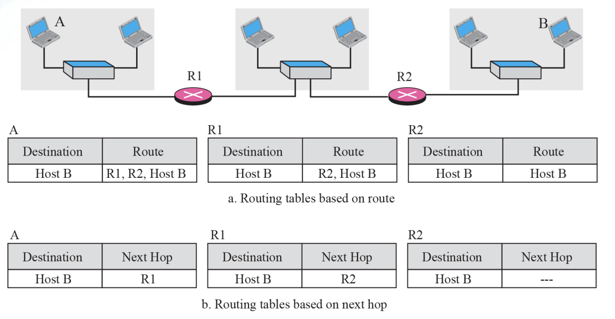
Next-hop method is
- To reduce the contents of a routing table
- The routing table holds only the address of the next hop instead of information about the complete route
6.4 Network-specific method
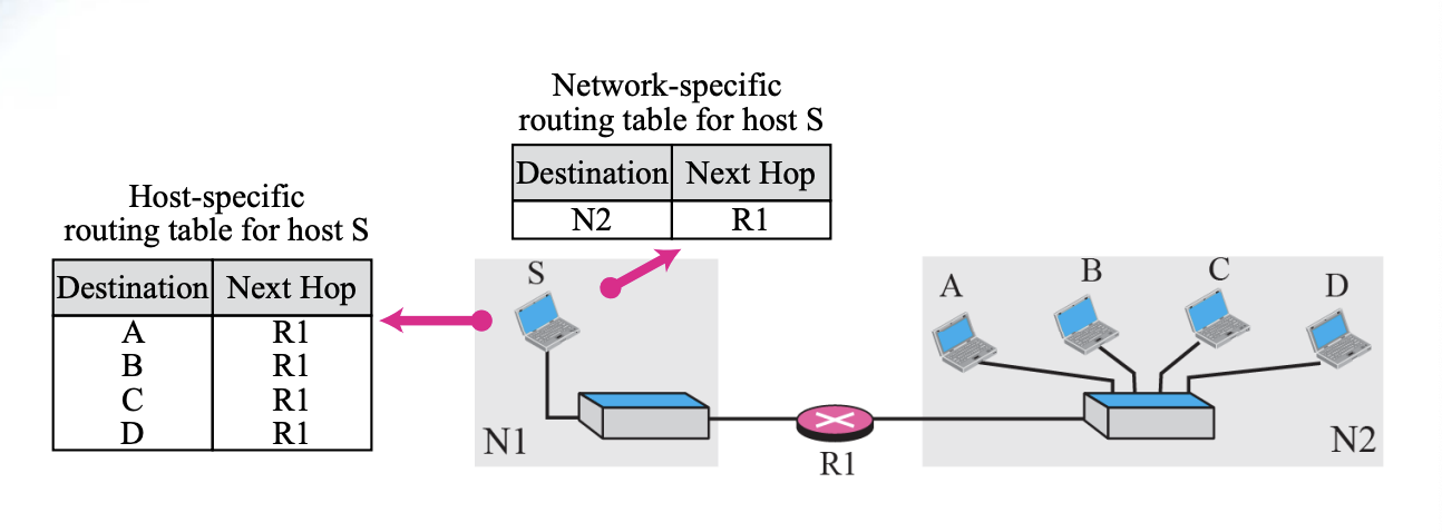
Network-specific method is
- To reduce the routing table and simplify the searching process
- Instead of having an entry for every destination host connected to the same physical network, we have only one entry that defines the address of the destination network itself
6.5 Host-specific routing
Host-specific method is
- The destination host address is given in the routing table
- ~inverse of the network-specific method
6.6 Default Routing
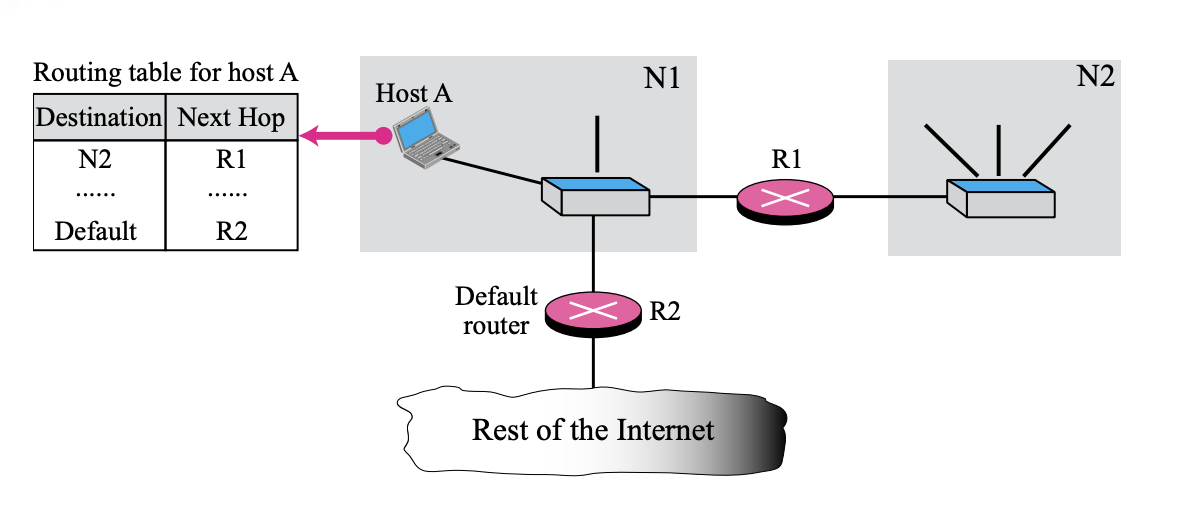
Default method is
- Instead of listing all networks in the entire Internet, host A can just have one entry (0.0.0.0) called the default.
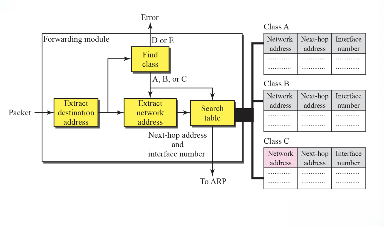
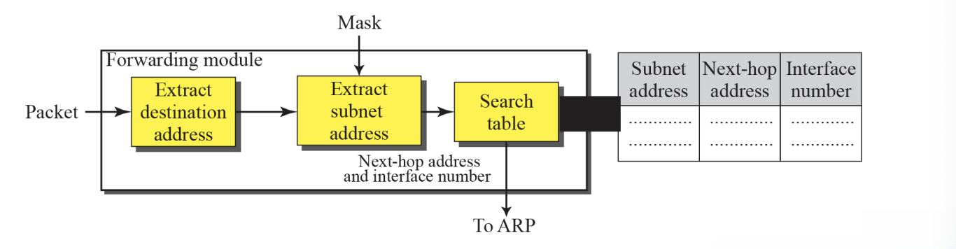
6.6 Forwarding with Classful Addressing
- In classful addressing, most of the routers in the global Internet are not involved in subnetting (Forwarding without Subnetting)
- A router has three tables (Class A, B, and C)
Each routing table has a minimum three columns
- The network address of the destination network tells us where the destination host is located (use network-specific forwarding normally)
- The next-hop address tells us to which router the packet must be delivered for an indirect delivery(empty for a direct delivery)
- The interface number defines the outgoing port from which the packet is sent out(m0, m1, and so on)

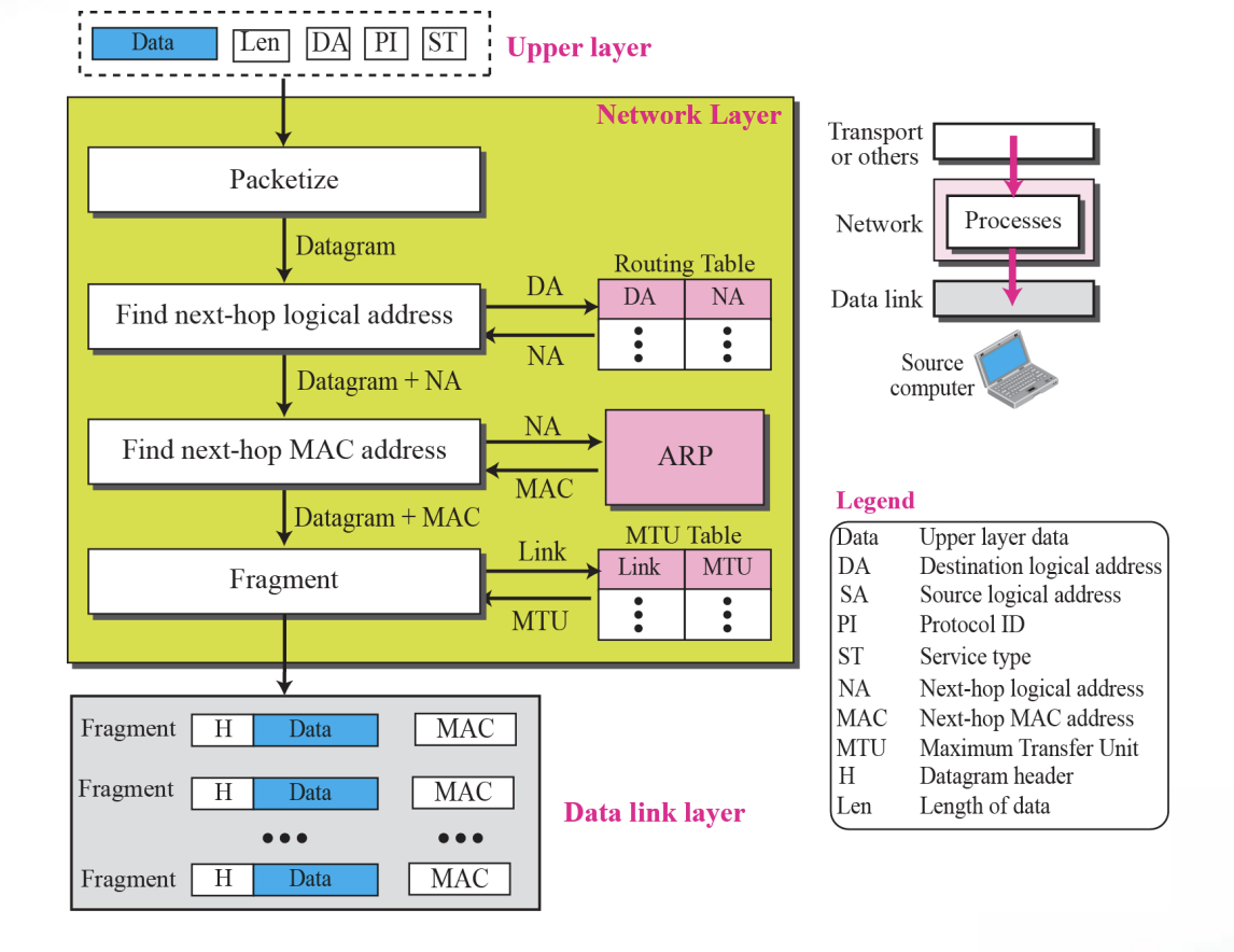
6.7 Forwarding without Subnetting (forwarding module step)
-
The destination address of the packet is extracted
-
A copy of the destination address is used to find the class of the address(shift 28bits to the right)
-
The result of Step 2 (class of the address) and destination address are used to extract the network address
-
The class of the address and destination address are used to find next-hop information (if no match is found, the default is used)
-
The ARP module (Chapter 7) uses the next-hop address and the interface number to find the physical address of the next router
-
Simplified forwarding module in classful address without subnetting
Figure 6.7
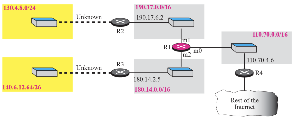
➭ Example 6.1
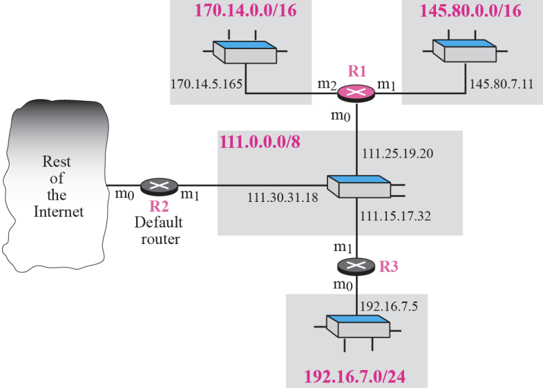
Figure shows an imaginary part of the Internet. Show the routing tables for router R1.
➭ Example 6.2
Router R1 receives a packet with destination address 192.16.7.14.
Show how the packet is forwarded.
[Solution]
The destination address is
11000000 00010000 00000111 00001110
A copy of the address is shifted 28 bits to the right. The result is
00000000 00000000 00000000 00001100 or 12.
The destination network is class C. The network address is extracted by
masking off the leftmost 24 bits of the destination address; the result is
192.16.7.0. The table for Class C is searched. The network address is found in the first row. The next-hop address 111.15.17.32. and the interface m0 are passed to ARP
➭ Example 6.3
Router R1 receives a packet with destination address 167.24.160.5.
Show how the packet is forwarded.

[Solution]
The destination address in binary is
10100111 00011000 10100000 00000101.
**A copy of the address is shifted 28 bits to the right. The result is
00000000 00000000 00000000 00001010 or 10.
**The class is B. The network address can be found by masking off 16 bits of the destination address, the result is 167.24.0.0. The table for Class B is searched. No matching network address is found. The packet needs to be forwarded to the default router. The next-hop address 111.30.31.18 the interface number m0 are passed to ARP.
6.8 Forwarding with Subnetting

- Figure shows a shows a simplified module for fixed length subnetting
- The module extract the destination address of the packet
- The destination address and the mask are used to extract the subnet address
- The table is searched using the subnet address to find the next-hop address and the interface number (if no match is found, the default is used)
- The next-hop address and the interface number are given to ARP
➭ Example 6.4 : Configuration

➭ Example 6.5
The router in Example 6.4 receives a packet with destination address 145.14.32.78. Show how the packet is forwarded.
(00100000)
[Solution]
The mask is /18. After applying the mask, the subnet address is 145.14.0.0.The packet is delivered to ARP (see Chapter 8) with the next-hop address 145.14.32.78 and the outgoing interface m0.
➭ Example 6.6
A host in network 145.14.0.0 in Figure 6.11 has a packet to send
to the host with address 7.22.67.91. Show how the packet is routed.
[Solution]
The router receives the packet and applies the mask (/18). The network address is 7.22.64.0. The table is searched and the address is not found. The router uses the address of the default router (not shown in figure) and sends the packet to
that router.
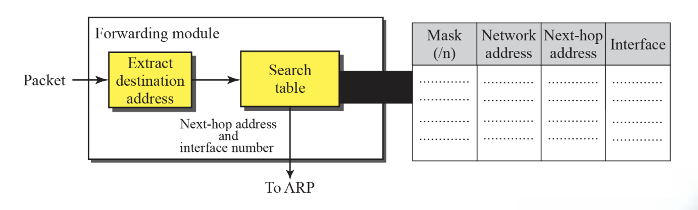
6.9 Forwarding with Classless Addressing
- In classless addressing, the whole address space is one entity (there are no classes)
- The mask(/n) is included in the table(an extra column)
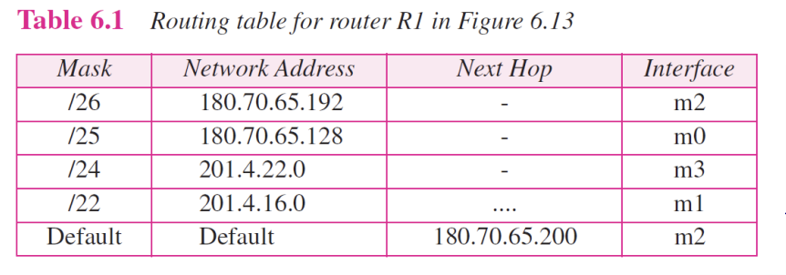
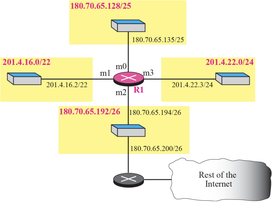
- Configuration for Example 6.7 Figure 6.13

Show the forwarding process if a packet arrives at R1 in Figure
6.13 with the destination address 180.70.65.140.
140 => (10001100)[Solution]
The router performs the following steps:
- The first mask (/26) is applied to the destination address. The result is 180.70.65.128, which does not match the corresponding network address.
- The second mask (/25) is applied to the destination address. The result is 180.70.65.128, which matches the corresponding network address. The next hop address (the destination address of the packet in this case) and the interface number m0 are passed to ARP for further processing.
➭ Example 6.9
Show the forwarding process if a packet arrives at R1 in Figure 6.13 with the destination address 201.4.22.35.

[Solution]
The router performs the following steps
- The first mask(/26) is applied to the destination address. The result is 201.4.22.0, which does not match the corresponding network address (row 1).
- The second mask (/25) is applied to the destination address. The result is 201.4.22.0, which does not match the corresponding network address (row2)
- The third mask (/24) is applied to the destination address. The result is 201.4.22.0, which matches the corresponding network address. The destination Address of the package and the interface number m3 are passed to ARP.
- Guessed topology for Example 6.11 :: Figure 6.14

- Hierarchical routing with ISPs :: Figure 6.17
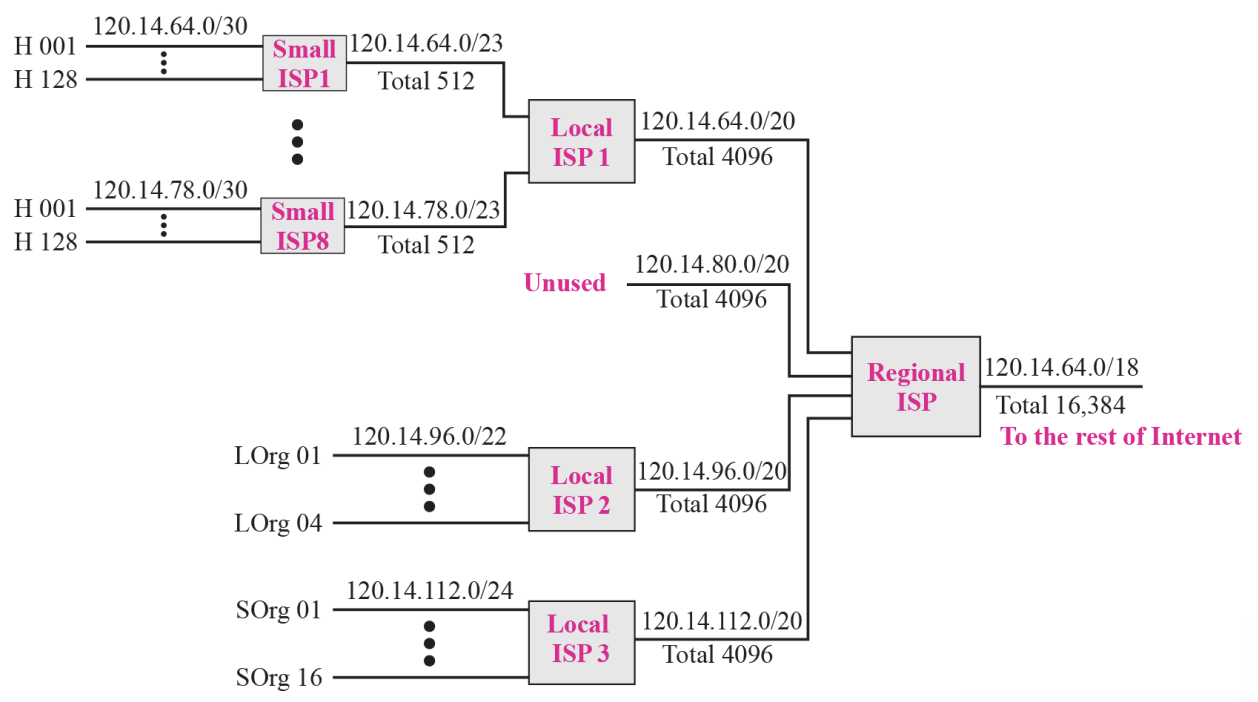
➭ Example 6.12
- As an example of hierarchical routing, let us consider Figure 6.17
- A regional ISP is granted 16,384 addresses starting from 120.14.64.0.
- The regional ISP has decided to divide this block into 4 sub-blocks, each with 4096 addresses.
- Three of these sub-blocks are assigned to three local ISPs, the second sub-blocks is reserved for future use.
- Note that the mask for each block is/20 because the original block with mask /18 is divided into 4 blocks
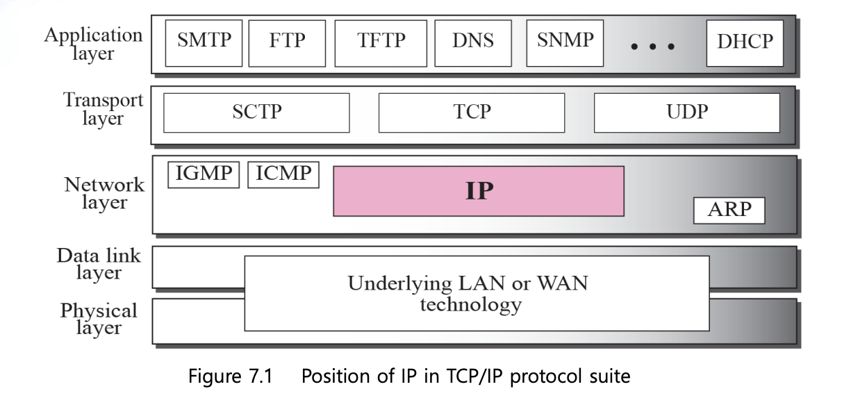
Chapter7 : Internet Protocol V4(IPv4)
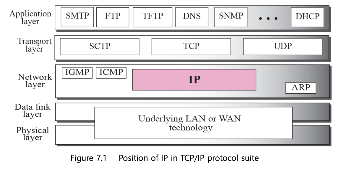
7.1 Internet Protocol
- The Internet Protocol (IP) is the transmission mechanism used by the TCP/IP Protocols
- IP is an unreliable and connectionless datagram protocol (a best-effort delivery service)
7.2 Datagram
- Packets in the IP layer are called a Datagrams
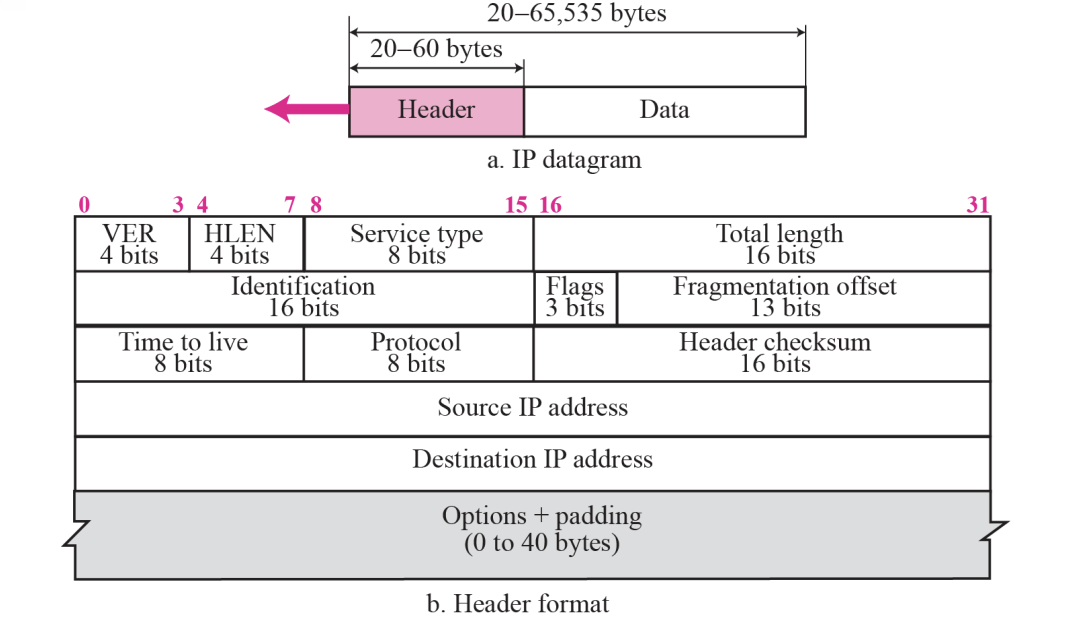
- A datagram is a variable-length packet consisting of two pares : header (20~60 bytes, for routing and delivery) and data
7.3 Header
1.Version(VER) : 4bits
- ~defines the version of the IP protocol
- If the machine is using some other version of IP, the datagram is discarded
2.Header length(HLEN, 20~60 bytes) : 4bits
- ~defines the total length of the datagram header in 4-bytes words
3.Service type : 8bits
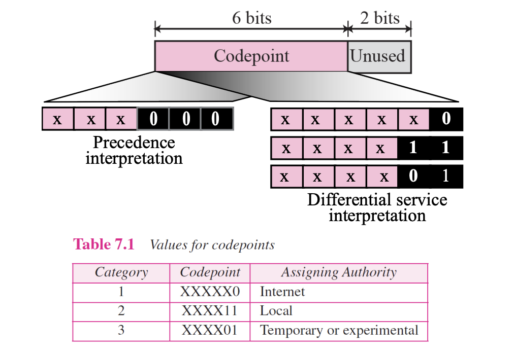
- This field, previously called Type of Service, is now called Differentiated Service
4.Total length : 16bits
- ~defines the total length (header plus data) of the IP datagram in bytes
- The length of data is calculated by :

- Since the field length is 16 bits, the total length of the IP datagram is limited to 65,535 (2^16 - 1) bytes
- The Ethernet protocol has a minimum and maximum restriction on the size of data that can be encapsulated in a frame(46~1500 bytes)

5.Identification : 16bits
6.Flags : 3bits
7.Fragmentation offset : 13bits
Identification & Flags & Fragmentation offset are used in fragmentation
8.Time to live : 8bits
- A datagram has a limited lifetime in its travel through an internet
- This field is mostly used to control the maximum number of hops (routers) visited by the datagram
- This value is approximately two times the maximum number of routes between any two hosts
- Each router decrements this number by one
- If this value, after being decremented, is zero, the router discards the datagram
- Another us of this field is to intentionally limit the journey of the packet (the value is 1 for the local network)
9.Protocol : 8bits
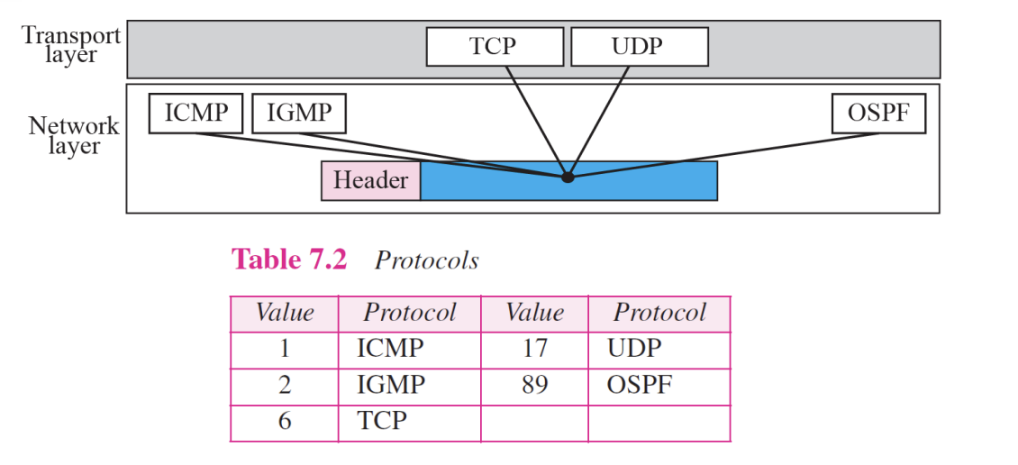
Multiplexing
- ~defines the higher-level protocol that uses the services of the IP layer
- An IP datagram can encapsulate data from several higher level protocols such as TCP, UDP, ICMP, and IGMP
10.Checksum : 16bits
•Source Adress (32 bits)
- ~defines the IP address of the source
- ~is unchanged during the time the IP datagram travels from the source host to the destination host
•Destination Adress (32bits)
- ~defines the IP address of the destination
- ~is unchanged during the time the IP datagram travels from the source host to the destination host
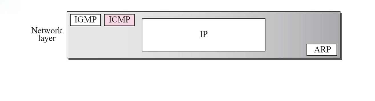
Chapter8 : Address Resolution Protocol [ARP]
8.1 Address Mapping
- The delivery of packets to a host or a router requires two levels of addressing : Logical and Physical Address
- We need to be able to map a Logical Address to its corresponding Physical Address and vice versa
- These can be done using either Static or Dynamic mapping
8.2 Internet Addresses
Static Mapping
- Creating a table that associates a logical address with physical address
- This table is stored in each machine on the network
- Each machine knows the IP address of another machine
- It has some limitations because Physical Address may change in the following ways : (changing NIC, moving mobile Computer)
Dynamic Mapping
- Each time a machine knows one of the two addresses(Logical or Physical), it can use a protocol to find the another one
- ARP(Address Resolution Protocol)
- Internet Addresses
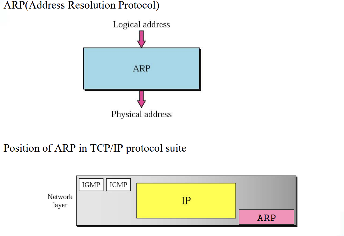
8.3 The ARP Protocol

-
ARP associates an IP address with its Physical Address
-
On a typical Physical network, such as a LAN, each device on a link is identified by a physical or station address that is usually imprinted on the NIC
-
ARP accepts a Logical Address from the IP protocol, maps the address to the corresponding Physical Address and pass it to the data link layer
-
ARP Operation
Figure 8.2
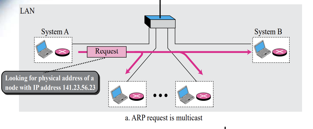
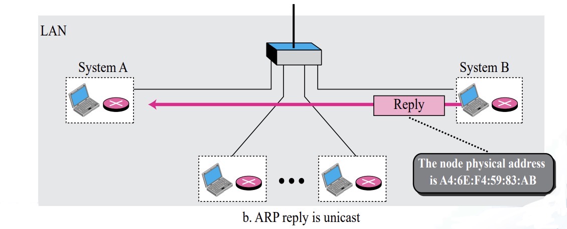
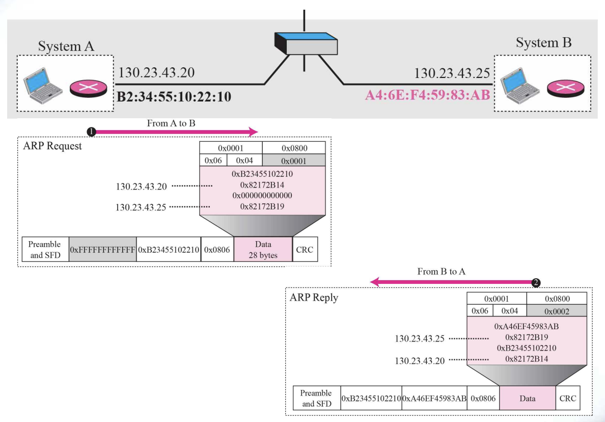
The ARP Protocol : ARP Operation ( A → B in Figure 8.2)
- A first checks whether B’s Physical address is stored in its cache and uses the stored information if it is
- If it is not in the cache, create an ARP Request message (ARP packet) and broadcast it to all hosts ( A→ B )
- B receives the ARP packet broadcast by A, records its physical address in the packet, and sends it to A in a reply message ( B → A )
- A stores B’s Physical Address in cache and uses it (usually for 20minutes)
- All other hosts that do not correspond to the destination address will ignore this message
- ARP Packet :: Figure 8.3
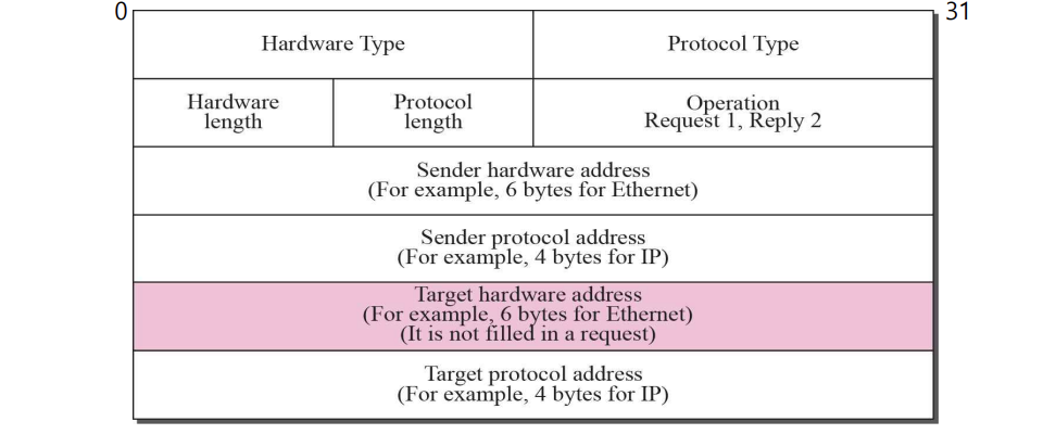
Packet Format
- Hardware type : the type of network (Ethernet : 1)
- Protocol type : defining protocol (IPv4 : 080016)
- Hardware length : the length of PHY address. in bytes
- Protocol length : the length of logical address. In bytes
- Operation : type of packet-ARP request(1), ARP reply(2)
- Sender hardware address : sender PHY address
- Sender protocol address : sender Logical address
- Target hardware address : receiver PHY address
- Target protocol address : receiver Logical address
- Encapsulation of ARP packet :: Figure 8.4
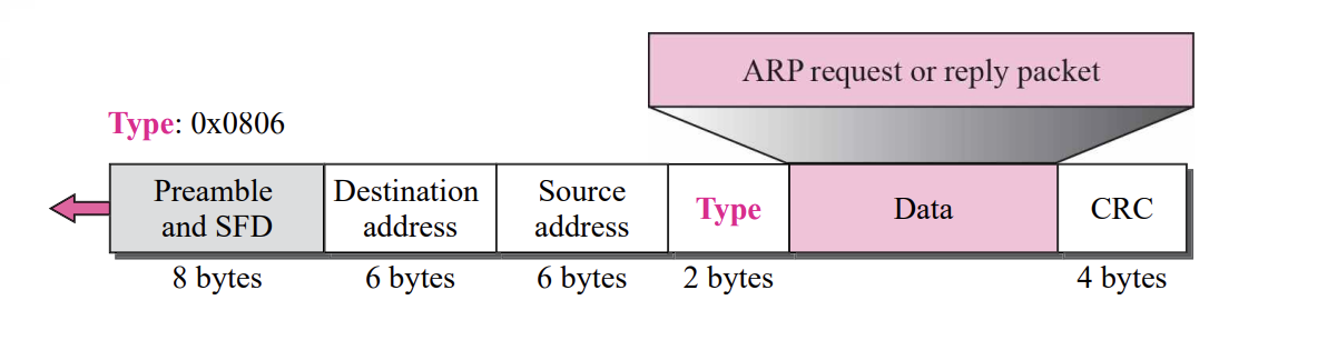
ARP Encapsulation step is
- Sender knows target IP address
- IP requests ARP to generate an ARP request message (sender Physical Address, IP Address, target IP address, Physical address)
- When delivered to the DLL, the sender address is the sender Physical address, and the target address is the PHY broadcasting address
- All hosts or routers receive frames and forward them to their ARP
- Target system sends ARP reply message including its own physical address (unicast)
- Sender receives a reply message and knows the target system's physical address
- IP datagram is encapsulated into a frame and unicast to the target
- Four cases using ARP :: Figure 8.5
Example8.1
A host with IP address 130.23.43.20 and physical address B2:34:55:10:22:10 has a packet to send to another host with IP address 130.23.43.25 and physical address A4:6E:F4:59:83:AB. The two hosts are on the same Ethernet network. Show the ARP request and reply packets encapsulated in Ethernet frames.
[Solution]
Figure 8.6 shows the ARP request and reply packets. Note that
the ARP data field in this case is 28 bytes, and that the individual
addresses do not fit in the 4-byte boundary. That is why we do not show the regular 4-byte boundaries for these addresses. Also note that the IP addresses are shown in hexadecimal.
- Example 8.1 :: Figure 8.6
8.4 ARP Package
- In the section, we give an example of a simplified ARP software package to show the components and the relationship between the components.
This ARP Package involves five modules
- a cache table
- Queues
- an output module
- an input module
- a cache-control module
- ARP Components :: Figure 8.3
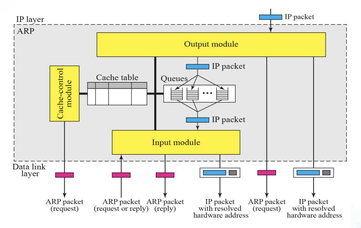
Cache Table
- Sender sends one or more IP datagrams to one destination
- Using the ARP protocol every time a datagram is sent is very inefficient (using cache table for this)
- When a destination physical address is received, it is stored in cache for a certain period of time
- Cache information is updated continuously, and information that is not updated for a certain period of time is automatically destroyed (typically 20 minutes)
Entry of Cache Table
- State : FREE, PENDING, RESOLVED
- Hardware type, Hardware length, Protocol length, Interface number
- Queue number
- Attempt : the number of times an ARP request is sent out for this entry
- Time-out : lifetime of an entry in seconds
- Hardware address : target PHY address
- Protocol address : target IP
Queues
- Maintain one queue, for each destination, to hold the IP packets while ARP tries to resolve the PHY. Address
- Output module sends unsolved packets into the corresponding queue
- Input module removes a packets from queue and send it, with the resolved PHY. Address
Chapter9 : Internet Control Message Protocol Version 4 [ICMPv4]
1.Services provided at the source computer
2.Processing at each router
3.Processing at the destination computer
9.1 Internet Protocol
Internet Protocol is
- The Internet Protocol (IP) is the transmission mechanism used by the TCP/IP protocols
- IP is an unreliable and connectionless datagram protocol (a best-effort delivery service)
➭ IP Datagram Figure

Datagram is
- Packets in the IP layer are called a Datagrams
- A datagram is a variable-length packet consisting of two pares : header(20~60 bytes, for routing and delivery) and data
The error detection method used by most TCP/IP protocols is called the checksum
- The checksum protects against the corruption that may occur during the transmission of a packet
- It is redundant information added to the packet
- The receiver repeats the same calculation on the whole packet including the checksum.
- -If the result is satisfactory, the packet is accepted; otherwise, it is rejected
9.2 Introduction
Lacks of IP
- Unreliable and connectionless datagram delivery
- Best-effort delivery service
- Lack of error control
- No error-reporting and error-correcting mechanism
- Lacks of mechanism for host and management queries
[ICMP has been designed to compensate for the above deficiencies]
- ICMP Encapsulation Figure 9.2
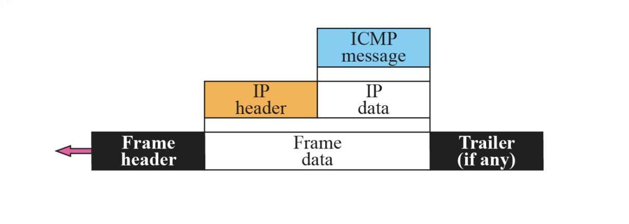
The value of the protocol field in IP datagram is 1 to indicate that the IP data is an ICMP message
9.2 Message
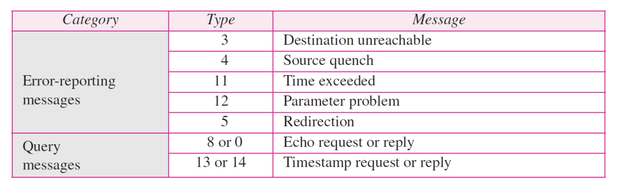
- ICMP messages are divided into two broad categories : error-reporting messages and query message
- The error-reporting messages report problems that a router or host may encounter when it processes an IP packet
- The query messages, which occur in pair, help a host or a network manager get specific information from a router or another host. Also, hosts can discover and learn about routers on their network and routers can help a node redirect its messages
➭ Table 9.1 ICMP messages
- General format of ICMP messages Figure 9.3
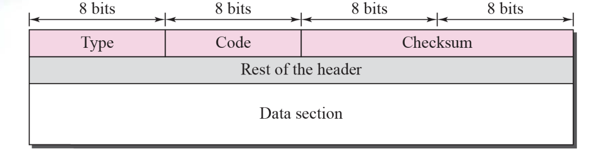
Message format
- Type : message type (8 bit)
- Code : specify the reason for the particular message
- Checksum : 16 bit
An ICMP message has an 8-byte header and a variable-size data section. Although the general format of the header is different for each message type, the first 4 bytes are common to all
⚙ ICMP always reports error messages to the original source➭ ICMP common field and message Type

Error-reporting messages
[important points about ICMP error messages]
-
No ICMP error message for a datagram carrying an ICMP error message
-
No ICMP error message for a fragmented datagram that is not the first fragment
-
No ICMP error message for a datagram having a multicast address
-
No ICMP error message for a datagram with a special address such as 127.0.0.0 or 0.0.0.0
-
Contents of data field for the error message
Figure 9.5
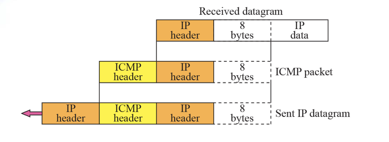
Contents of data field for error messages
-
The first 8 bytes provide information about the port numbers (UDP and TCP) and sequence number (TCP)
-
Destination-unreachable format
Figure 9.6
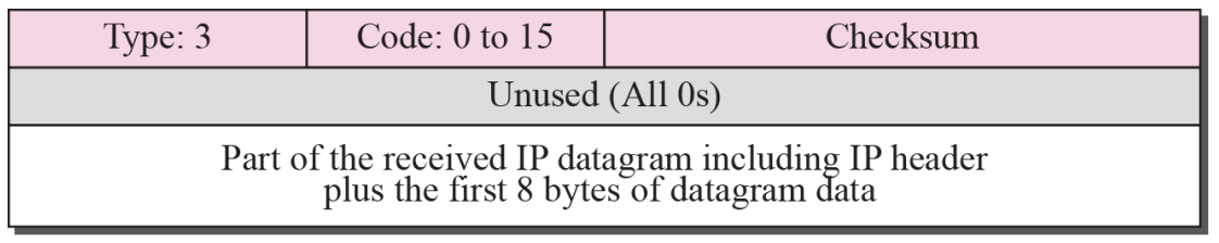
Destination unreachable
- When a router cannot route a datagram or a host cannot deliver a datagram, the datagram is discarded and the router or host send a destination unreachable message back to the source
- Source-quench format Figure 9.7
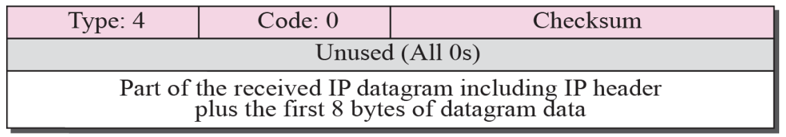
- A source-quench message informs the source that a datagram has been discarded due to congestion in a router or the destination host. The source must slow down the sending of datagrams until the congestion is relieved.
- There is no flow-control or congestion-control mechanism in the IP Protocol.
- One source-quench message is sent for each datagram that is discarded due to congestion.
- Time-exceeded message format Figure 9.8
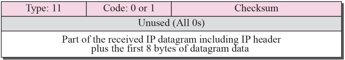
- Whenever a router decrements a datagram with a time-to-live value to zero, it discards the datagram and sends a time-exceeded message to the original source
- When the final destination does not receive all of the fragments in a set time, it discards the received fragments and sends a time-exceeded message to the original source
- In a time-exceeded message, code 0 is used only by routers to show that the value of the time-to-live field is zero. Code 1 is used only by the destination host to show that not all of the fragments have arrived within a set time
- Parameter-problem message format Figure 9.9
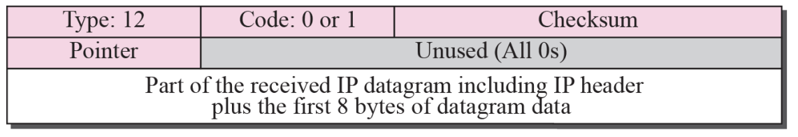
⚙ A Parameter-Problem Message can be created by a router or the destination hostParameter problem is
- Code 0 : Main header Problem
- Code 1 : Problem in the option field
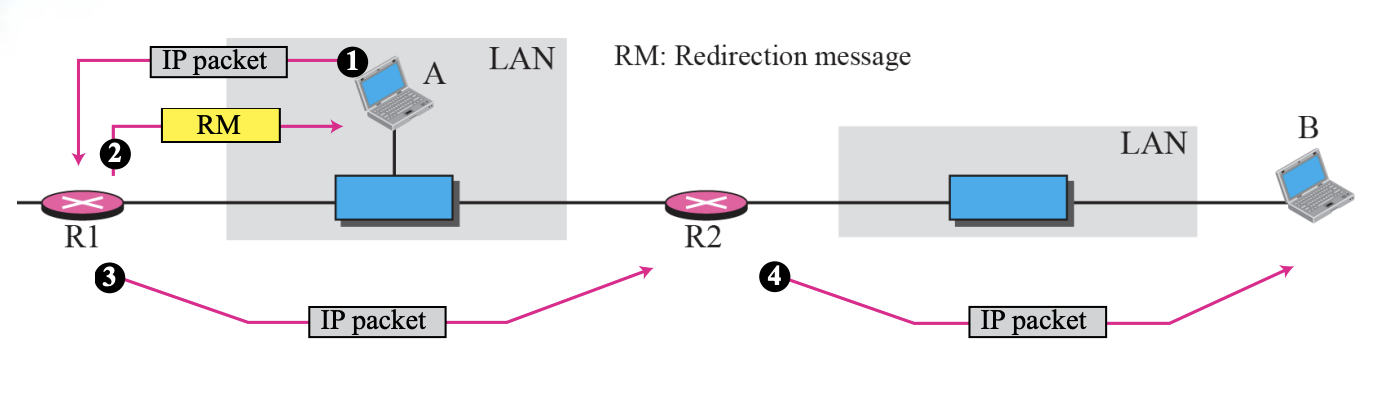
- Redirection concept Figure 9.10
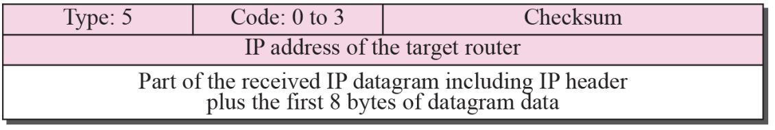
- Redirection message format Figure 9.11
Redirection is
- When a host send a datagram, which is destined for another network, to the wrong router, the router that receives the datagram will forward the datagram to the correct route, However, to update the routing table of host, it send a redirection message to host.
⚙ A redirection message is sent from a router to a host on the same Local Network.Codes
- Code 0: N
- Code 1: Host specific
- Code 2: Network specific (specified service)
- Code 3: Host specific (specified service)
Query
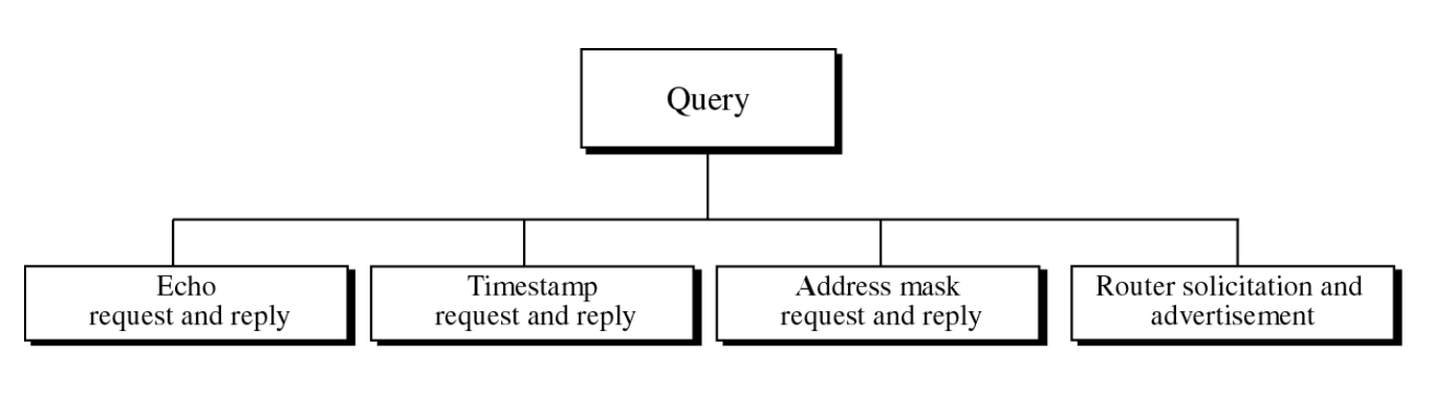
Query messages
- Diagnose some network problems
- Echo-request and echo-reply message Figure 9.12
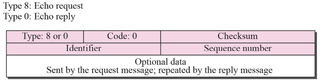
- An echo-request message can be sent by a host or router.
An echo-reply message is sent by the host or router that
receives an echo-request message. - Echo-request and echo-reply messages can be used by
network managers to check the operation of the IP
protocol. - Echo-request and echo-reply messages can test the
reachability of a host.
This is usually done by invoking the ping command
Timestamp Request and Reply
- The timestamp-request and timestamp-reply messages can be used to synchronize two clocks in two machines if the exact one-way time duration is known
- Timestamp-request and timestamp-reply messages can be used to calculate the round-trip time between a source and a destination machine even if their clocks are not synchronized
- Each field is represented by the unit of Milliseconds from midnight in Universal Time
- Timestamp-request and timestamp-reply message format Figure 9.13
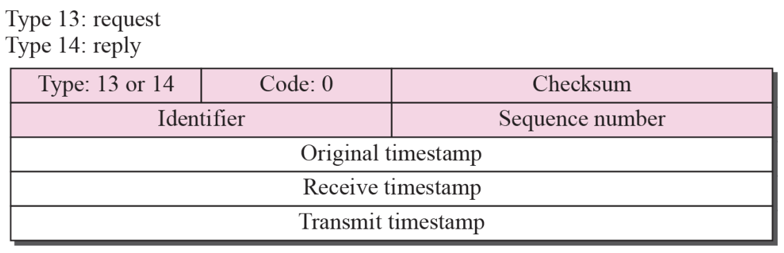
Steps
- Sender create a timestamp-request message
- Inset the sending time to Original timestamp field
- Other 2 fields is 0
- Receiver create the timestamp to same field
- Copy the value of the original timestamp to same field
- Insert the receiving time of the request message to the receive timestamp
- Insert the sending time of the reply message to the transmit timestamp
Timestamp Request and Reply
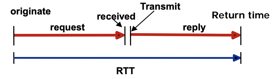
⚙ Timestamp-request and timestamp-reply messages can be used to calculate the round-trip time between a source and a destination machine even if their clocks are not synchronizedFormulas of Round-trip time
- Sending time = receive timestamp - original timestamp
- Receiving time = packet return time - transmit timestamp
- Round-trip time = sending time + receiving time
➭Example
1.ㅤGiven the following information
- Value of original timestamp : 46
- Value of receive timestamp : 59
- Value of transmit timestamp : 60
- Time the packet arrived : 67
2.ㅤWe can calculate
- Sending time = 59 - 46 = 13 milliseconds
- Receiving time = 67 - 60 = 7 milliseconds
- Round-trip time = 13 + 7 = 20 milliseconds
3.ㅤWe have
- Time Difference = 59 - (46 + 10) = 3
Checksum
“In ICMP the checksum is calculated over the entire message (header and data)”
Checksum Calculation
The Sender uses a conservative operation of 1 to perform the following steps
- Make the sum field zero
- Obtain the sum of 16-bit words for header and data
- Consensual remuneration is obtained to obtain a sum of inspections
- Saves the sum of checks in the sum of checks field
Checksum Testing
Receiver performs the next step using a conservative operation of 1
-
Obtain the sum of 16-bit words for header and data
-
calculate the remuneration of the sum
-
If the result of the previous step is 16 zeros, the message is accepted, otherwise refusal
-
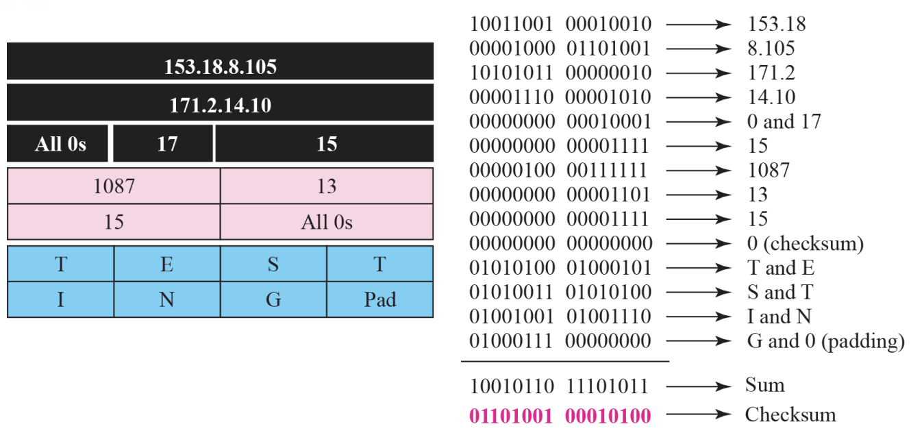
Example 9.1
Figure 9.14
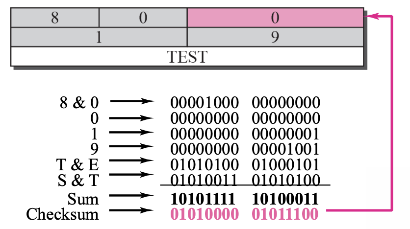
Figure 9.14 shows an example of checksum calculation for a simple echo-request message. We randomly chose the identifier to be 1 and the sequence number to be 9. The message is divided into 16-bit (2-byte) words. The words are added together added together and the sum is complemented. Now the sender can put this value in the checksum field.
Chapter10-11 : MIP & Routing
Mobile IP
“The main problem that must be solved in providing mobile communication using the IP Protocol is addressing”
- Stationary Host
- Mobile Host
A. Stationary Host
Assume that the host with the original IP address is connected to a particular network and in a quiesced state
B. Mobile host
If a host moves from one network to another, the IP address structure must also change
Mobile hosts Address
- Solution 1 : Changing the Address
- Having a mobile host change its address when it goes to a new network
- Hosts acquire and use new addresses on new networks using DHCP
- The problems are as follows:
- Reboot every time a host moves to another network
- Data transfer is interrupted when a host moves to another network during data transfer
- Solution 2 : Two Addresses
- Having a mobile host change its address when it goes to a new network
- home address : original address, permanently used, connecting the host to the home network
- care-of address : When a host moves to another network as a temporary address, the host changes to the address of the foreign network where it arrived
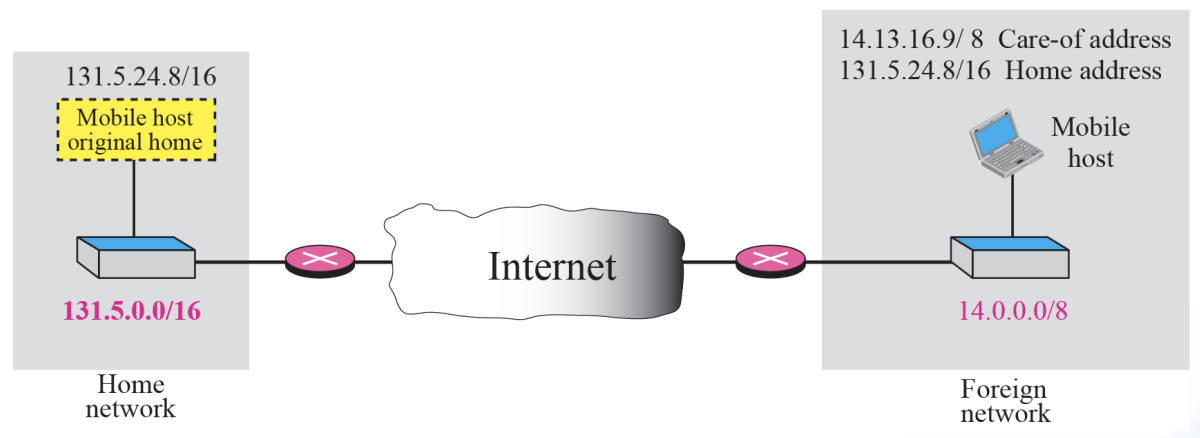
- Home Agent
- Routers connected to the home network of the mobile host
- When a remote host sends a packet to a moving host, it acts on behalf of the moving host, sending the packet to the foreign agent
- Foreign Agent
- Routers connected to a foreign network
- Forward packets received from the home agent to the mobile host
- must have a home address and a table address
Data transfer
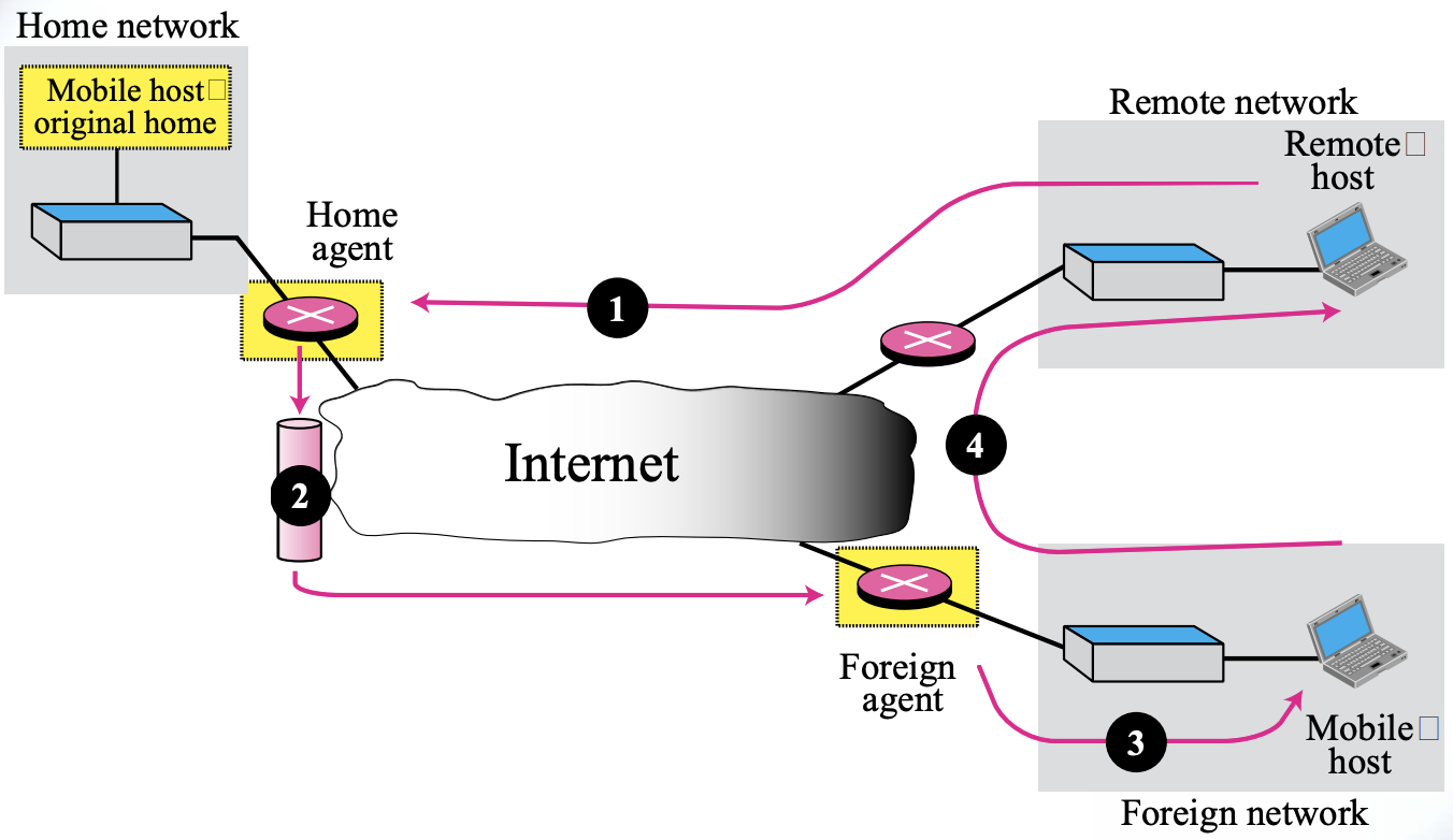
- Transfer Processes Remote host to home agent (route 1)
-
Send a packet with your own address as the source address and your home address as the destination address
Home Agent to Foreign Agent (route 2)
-
After receiving a packet, receive the packet and send it to a foreign agent using the tunneling concept
Out-of-town agent to mobile host (route 3)
-
Extract the original packet, refer to the registration table, and find the address of the mobile host's trust
From mobile host to remote host (route 4)
-
Send as normal
-
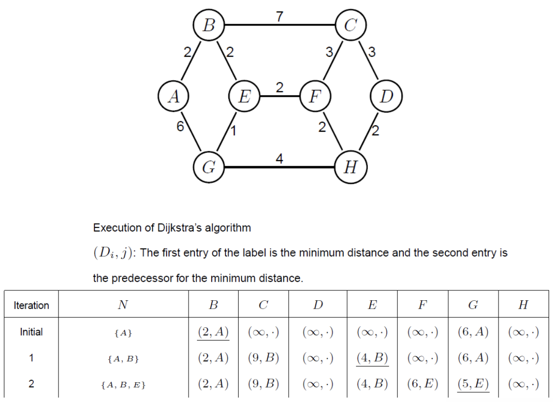
Ex. Routing protocol Dijkstra’s algorithm
Chapter13 : Introduction to the Transport Layer
13.1 Transport-Layer Services
The transport layer is located between the network layer and the application layer.
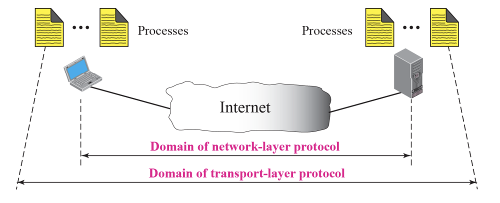
-
The transport layer is responsible for providing services to the application layer; it receives services from the network layer.
-
As a network-layer protocol, IP can deliver the message only to the destination computer
-
The message still needs to be handed to the correct process
-
Port Numbers :: Figure 13.2
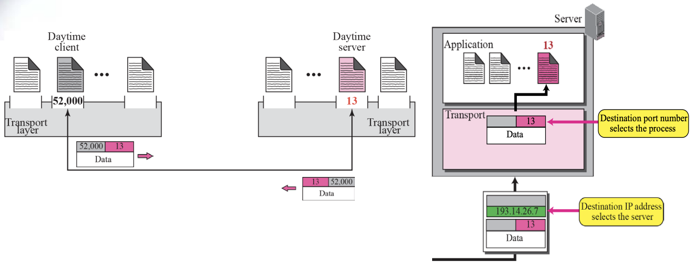
- For communication, we must define
[Local host, Local Process, Remote host, Remote Process]
- The local host and the remote host are defined using IP Address
- To define the processes, we need identifiers called Port Number
- Socket Address :: Figure 13.5
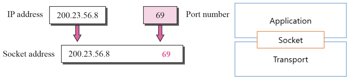
-
The combination of an IP address and a port number is called a Socket Address
-
The IP header contains the IP addresses
-
UDP needs two identifiers, the IP address and the port number
-
The UDP header contains the port numbers
-
Pushing or Pulling :: Figure 13.8
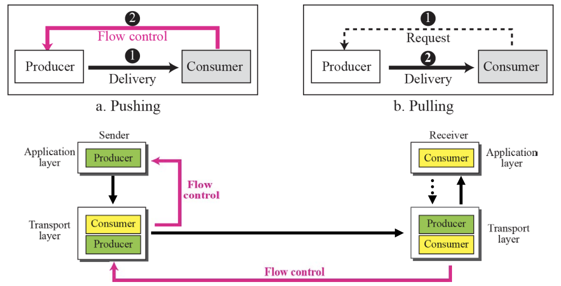
Flow Control
- The balance between the production rate and the consumption rate between the information producer and the consumer is important
- The method of transferring information from the producer to the consumer is as follows :
- Pushing: delivered by the producer without a consumer request.
- Pulling: Forward only if requested by the consumer.
Flow Control can be implemented normally by using two buffers
- Error control at the Transport Layer :: Figure 13.10
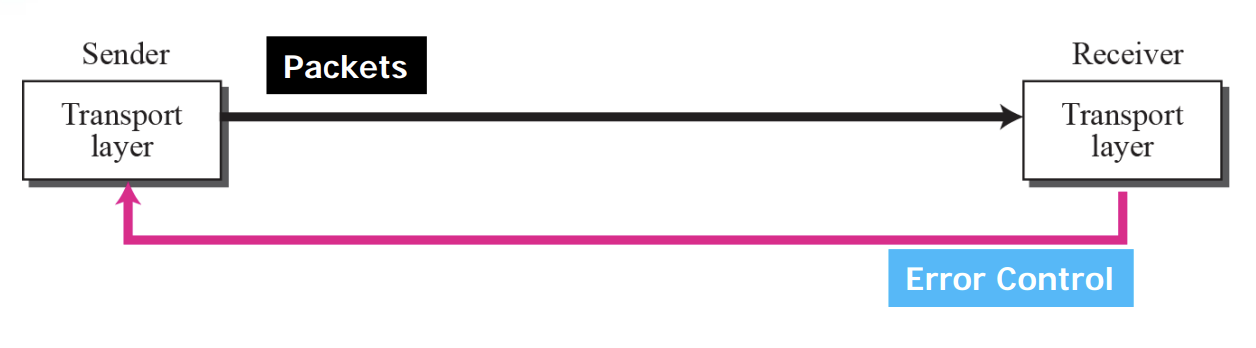
Error Control at the Transport Layer is responsible to
- Detect and Discard corrupted packets
- Keep track of lost and discarded packets and resend them
- Recognize duplicate packets and discard them
- Buffer out-of order packets until the missing packets arrive
Error Control
Sequence number is
- Serial number assigned to the packet
- Which packets should be retransmitted
- Which packets are duplicated
- Which packets arrived out of order
acknowledgment (ACK)
is a signal that is passed between communicating processes, computers or devices to signify acknowledgment, or receipt of message, as part of a communication protocol.
The negative-acknowledgement (NAK or NACK)
is a signal that is sent to reject a previously received message or to indicate some kind of error. Acknowledgments and negative acknowledgments inform a sender of the receiver's state so that it can adjust its own state accordingly.
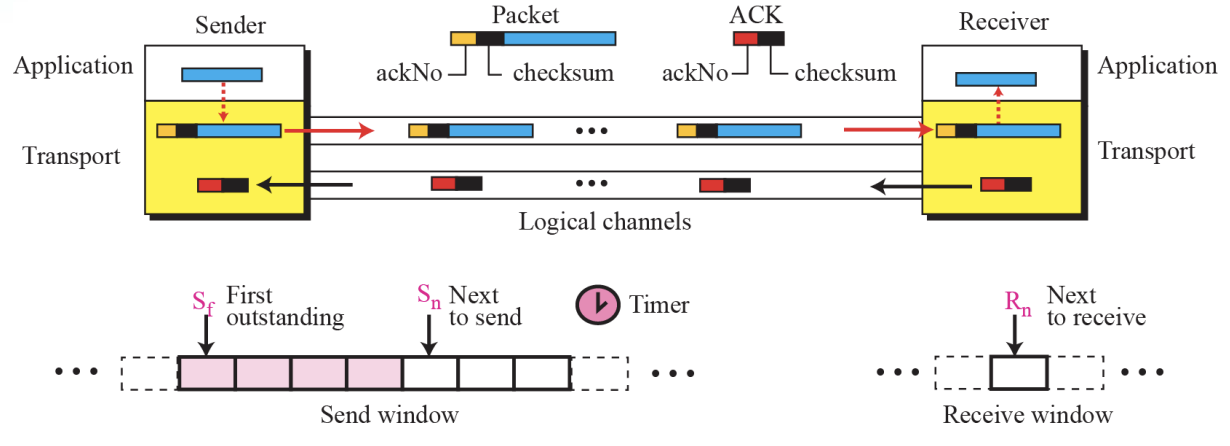
⚙ For error control, the sequence numbers are modulo 2^m, where m is the size of the sequence number field in bits.- Sliding window in circular format :: Figure 13.11
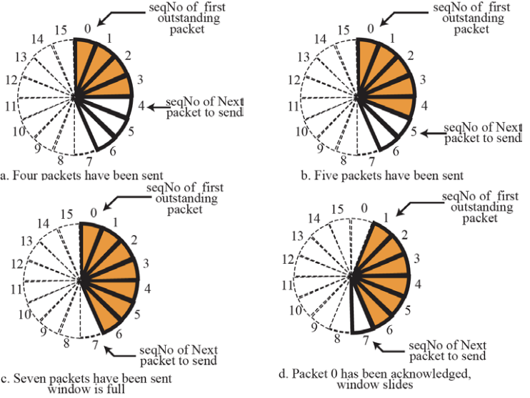
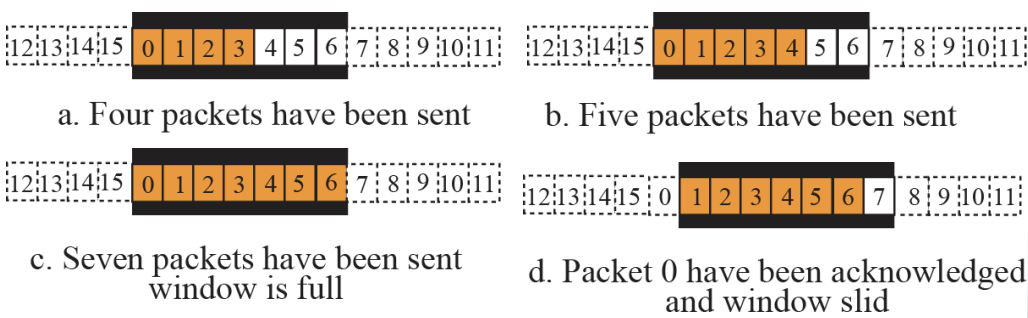
- Sequence Numbers : modulo 16 , Size of Window : 7
13.2 Congestion Control
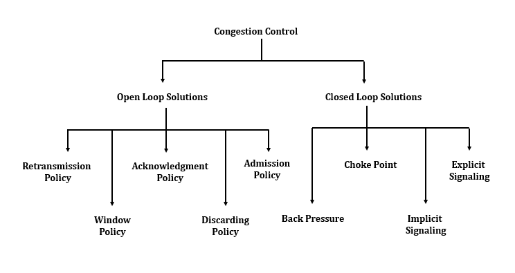
Congestion Control is
~refers to the mechanisms and techniques to control the congestion and keep the load below the capacity
⚙ **NEED of Congestion Control:**- It is not possible to completely avoid the congestion but it is necessary to control it.
- Congestions leads to a large Queue Length.
- It results in Buffer Overflow & Loss of Packets.
- So the congestion control is necessary to ensure that the user gets the negotiated Quality of Services.
A. Open-Loop Congestion Control
(Open loop congestion control policies are applied to prevent congestion before it happens)
- is handled by either the source or the destination
- Retransmission Policy : retransmission timer
- Window Policy : Selective Repeat & Go-Back-N window for congestion control
- ACK reply policy : Timer & Cumulative ACK
B. Closed-Loop Congestion Control
(Closed loop congestion control techniques are used to treat or alleviate congestion after it happens)
- The size of the window at the sender can be flexible
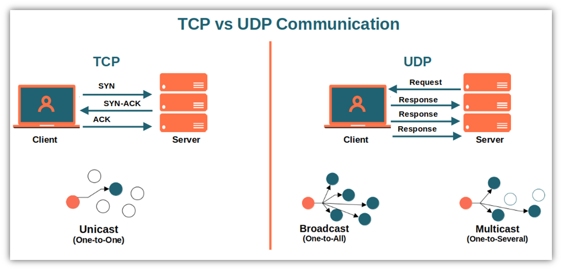
Connection-Oriented vs Connectionless Service
| S. No | Comparison Parameter | Connection-oriented Service | Connection Less Service |
|---|---|---|---|
| 1. | Related System | It is designed and developed based on the telephone system. | It is service based on the postal system. |
| 2. | Definition | It is used to create an end to end connection between the senders to the receiver before transmitting the data over the same or different network. | It is used to transfer the data packets between senders to the receiver without creating any connection. |
| 3. | Virtual path | It creates a virtual path between the sender and the receiver. | It does not create any virtual connection or path between the sender and the receiver. |
| 4. | Authentication | It requires authentication before transmitting the data packets to the receiver. | It does not require authentication before transferring data packets. |
| 5. | Data Packets Path | All data packets are received in the same order as those sent by the sender. | Not all data packets are received in the same order as those sent by the sender. |
| 6. | Bandwidth Requirement | It requires a higher bandwidth to transfer the data packets. | It requires low bandwidth to transfer the data packets. |
| 7. | Data Reliability | It is a more reliable connection service because it guarantees data packets transfer from one end to the other end with a connection. | It is not a reliable connection service because it does not guarantee the transfer of data packets from one end to another for establishing a connection. |
| 8. | Congestion | There is no congestion as it provides an end-to-end connection between sender and receiver during transmission of data. | There may be congestion due to not providing an end-to-end connection between the source and receiver to transmit of data packets. |
| 9. | Examples | Transmission Control Protocol (TCP) is an example of a connection-oriented service. | User Datagram Protocol (UDP), Internet Protocol (IP), and Internet Control Message Protocol (ICMP) are examples of connectionless service. |
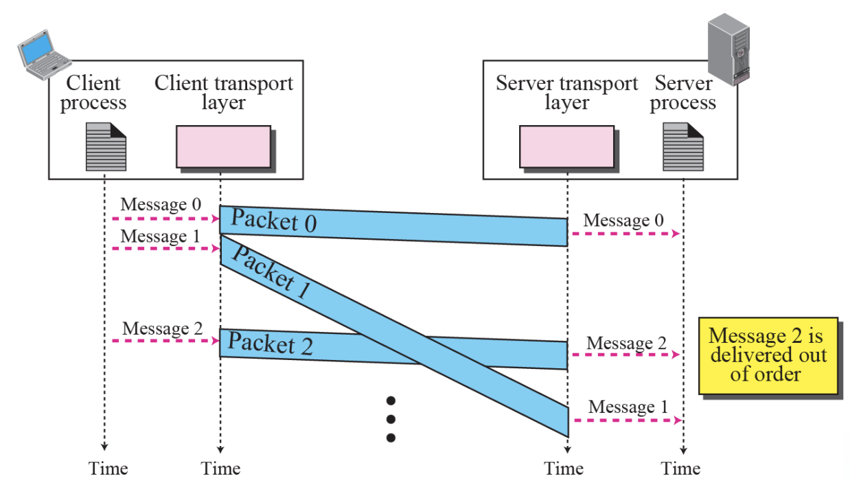
- Connectionless Service :: Figure 13.13
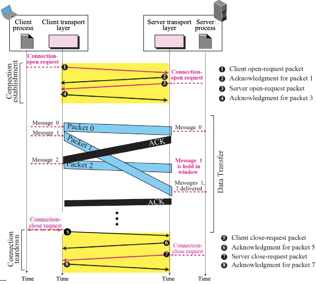
- Connection-Oriented Service :: Figure 13.14
13.3 Transport-Layer Protocols
To better understand the behavior of transport-layer protocols,
- We start with the simplest one and gradually add more complexity
- The TCP/IP protocol uses a transport layer protocol that is either a modification or a combination of some of these protocols.
- Simple Protocol :: Figure 13.16
Simple Protocol is
- Connection Less Protocol
- No Flow Control and Error Control
The design of the simplest protocol with no flow or Error Control
⚙ The simple protocol is a ConnectionLess Protocol that provides neither flow nor Error Control- Example 13.4 :: Figure 13.18
- Figure 13.18 shows an example of communication using this protocol. It is very simple. The sender sends packets one after another without even thinking about the receiver.
Stop-And-Wait Protocol
- It is Connection-Oriented Protocol
- ~uses both Flow and Error Control
Only one packet and one acknowledgement can be in the channels at any time
- Sliding window with size = 1
- Do not send the following packets until “acknowledge" is received
- Add Checksum to check for packet corruption
- Timer start when sending, Timer stop when Ack comes
- Resend packets if corrupted or lost
Sequence Number
- Use to prevent duplicate reception
- Adding an Sequence Number Field to the Packet Header Part
- Receive x order number, use x+1 confirmation answer number
Acknowledgement number
- The next packet order number that the receiver expects to receive
- In Stop-and-Wait protocol, flow control is achieved by forcing the sender to wait for an acknowledgment, and error control is achieved by discarding corrupted packets and letting the sender resend unacknowledged packets when the timer expires.
- In the Stop-and-Wait protocol, we can use a 1-bit field to number the packets. The sequence numbers are based on modulo-2 arithmetic.
- In the Stop-and-Wait protocol, the acknowledgment number always announces in modulo-2 arithmetic the sequence number of the next packet expected.
- All calculation in the Stop-and-Wait protocol is in modulo. ⚙️
➭Example 13.5
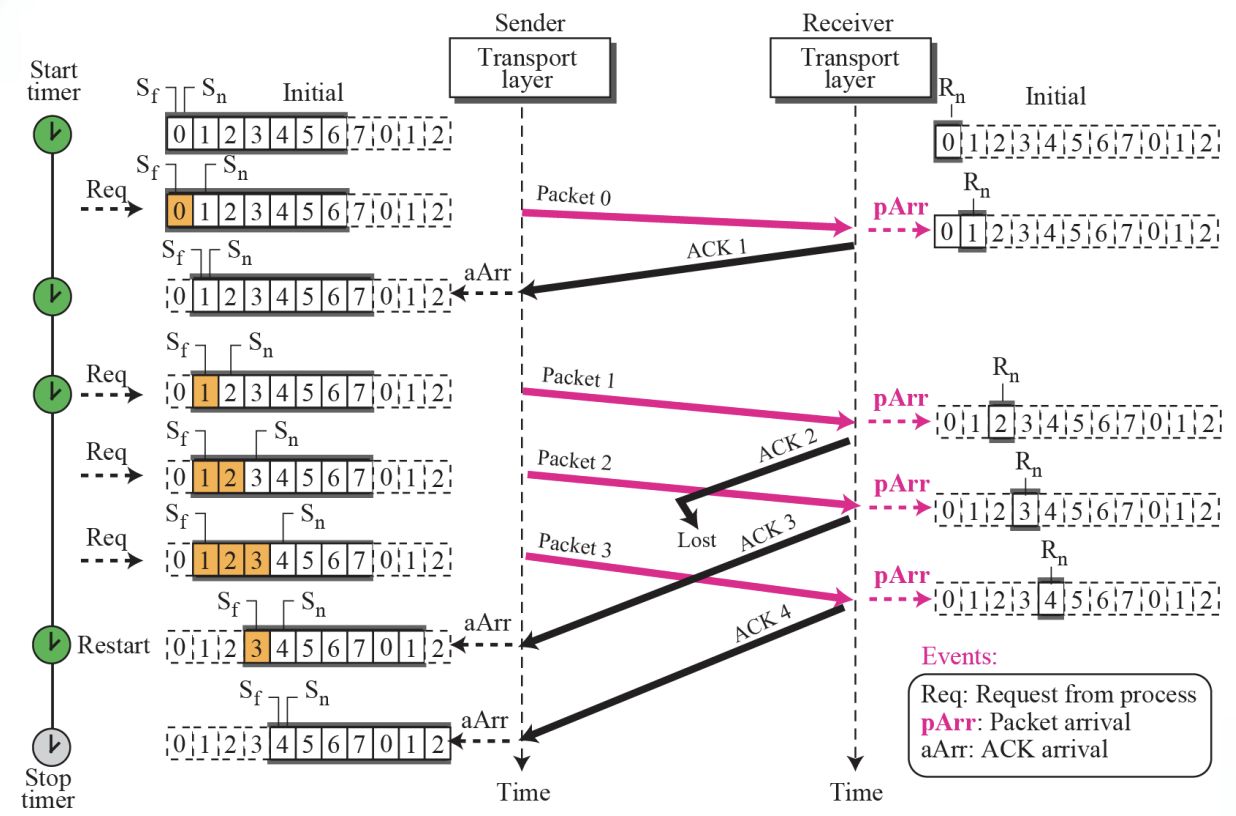
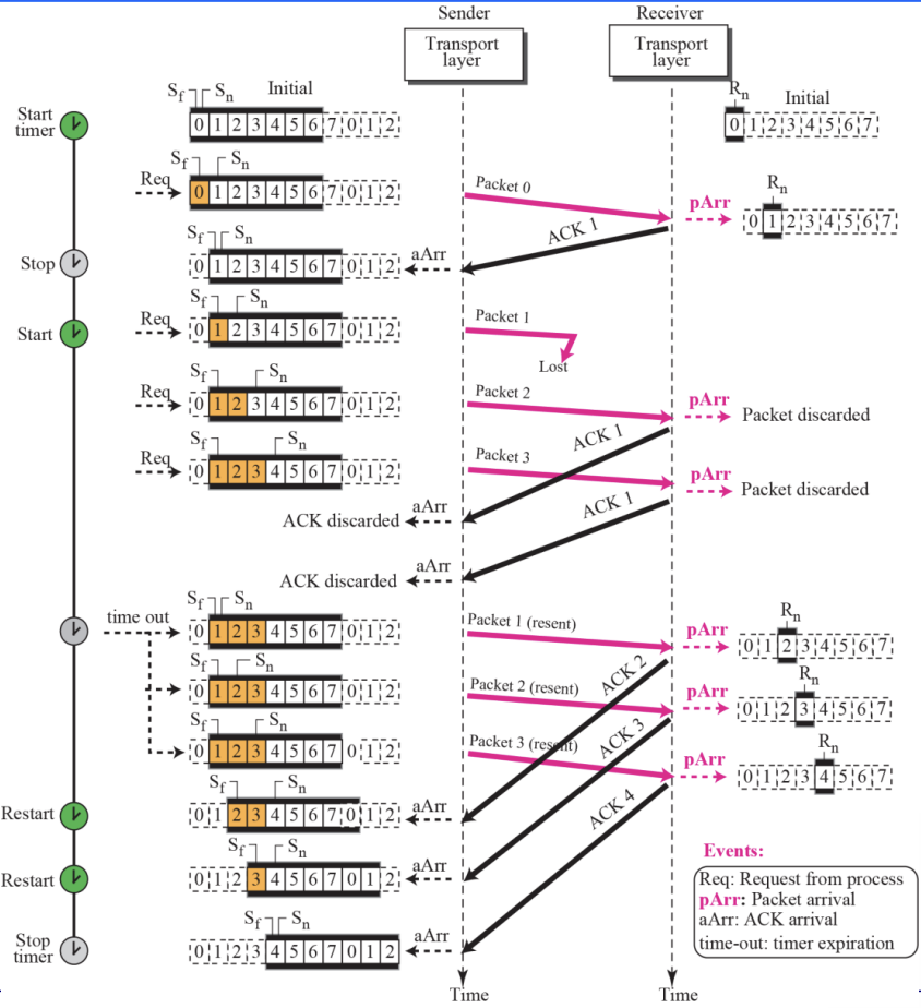
- Go-Back-N Protocol Figure 13.22
Go-Back-N Protocol is
- ~can send several packets before receiving acknowledgments
- but the receiver only buffer one packets
Sequence Numbers
- In the Go-Back-N Protocol, the sequence numbers are modulo 2^m, where m is the size of the sequence number field in bits.
Acknowledgement Numbers
-
In the Go-Back-N protocol, the acknowledgment number is cumulative and defines the sequence number of the next packet expected to arrive
-
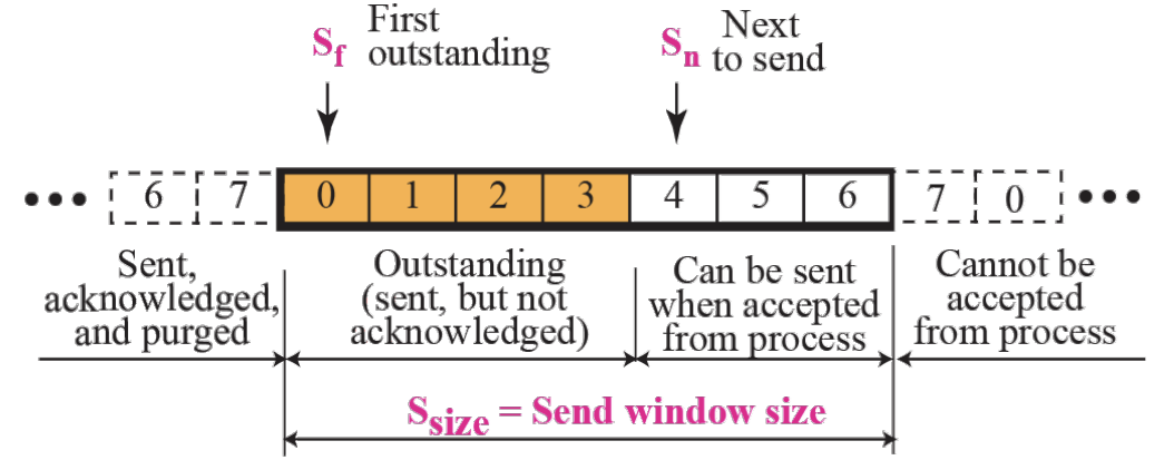
Send window for Go-Back-N :: Figure 13.23
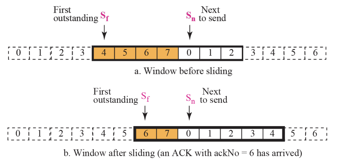
- Sliding the send window :: Figure 13.24
Send Window
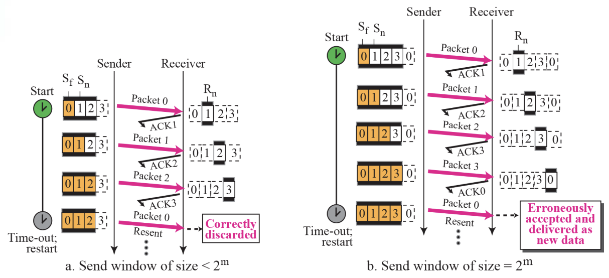
- The send window is an abstract concept defining an imaginary box of maximum size = 2^m-1 with three variables : Sf, Sn, and Ssize.
- The send window can slide one or more slots when an error-free ACK with ackNo between Sf and Sn (in modular arithmetic) arrives.
- Receive window for Go-Back-N Figure 13.25
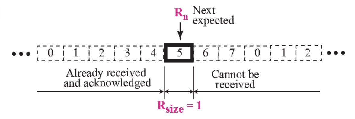
Receive Window is
- The receive window is an abstract concept defining an imaginary box of size 1 with one single variable Rn. The window slides when a correct packet has arrived; sliding occurs one slot at a time.
[Timers]
- ~resend all outstanding packets when this timer expire
[Resending Packets]
-
On a time-out, the machine goes back N locations and resends all packets
-
Send window size for Go-Back-N :: Figure 13.27
Send Window Size is
- In the Go-Back-N Protocol, the size of the send window must be less than 2^m; the size of the receive window is always 1.
- 2-Examples
Chapter14 : User Datagram Protocol [UDP]
14.1 Introduction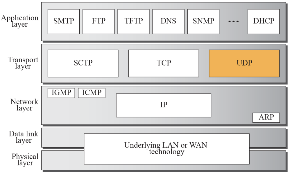
UDP lies between the application layer and the IP layer and, like TCP, serves as the intermediary between the application programs and the network operations
- UDP create a process-to-process communication
- UDP is called a connectionless, unreliable transport protocol
- It performs very limited error checking
- UDP is a very simple protocol using a minimum of overhead
- If a process wants to send a small message and does not care much about reliability, it can use UDP
14.2 User Datagram
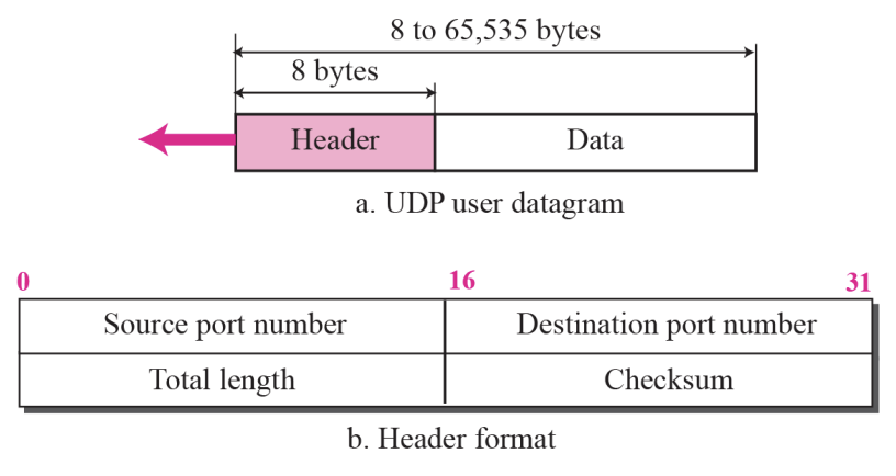
- Source port number
- ~ is the port number used by the process running on the source host
- Destination port number
- ~ is the port number used by the process running on the destination host
- Total length
- ~ is a 16-bit field that defines the total length of the user datagram, header + data
- Checksum
UDP Services
- Process-to-Process Communication
- Connectionless Service
- Flow Control
- Error Control
- Congestion Control
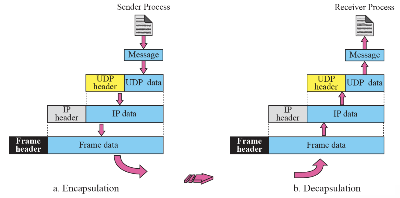
- Encapsulation and Decapsulation
- Queuing
- Multiplexing and Demultiplexing
- Comparison between UDP and Generic Simple Protocol
[1] Process-to-Process Communication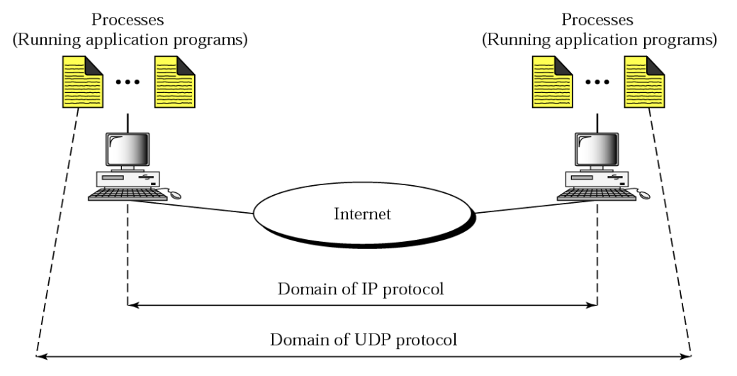
- The IP is responsible for communication at the computer level
- As a network-layer protocol, IP can deliver the message only to the destination computer
- The message still needs to be handed to the correct process
Connectionless Service Flow, Error and Congestion Control
Connectionless Service
- UDP provides a connectionless service
- ~ means that each user datagram sent by UDP is an independent datagram
- ~ means that each user datagram can travel on a different path
Flow and Error Control
- UDP is a very simple, unreliable transport protocol
- There is no flow control, and hence no window mechanism
- The receiver may overflow with incoming messages
- There is no error control mechanism in UDP except for the checksum
- When the receiver detects an error through the checksum, the user datagram is silently discarded
Congestion Control
- UDP is a connectionless protocol
- It does not provide congestion control
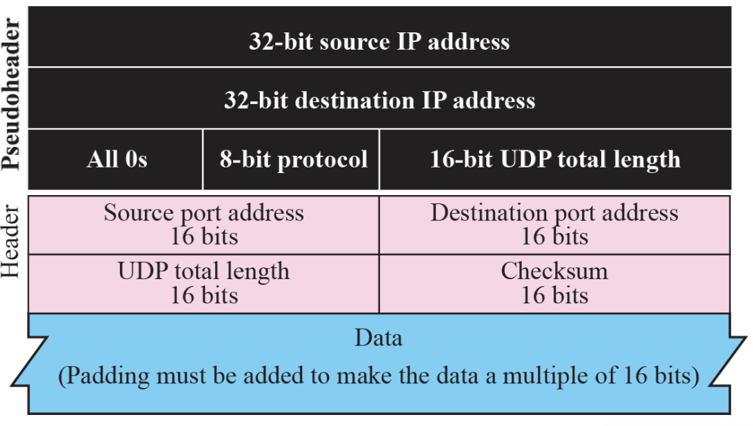
- Pseudo header for checksum calculation :: Figure 14.3
- Checksum calculation for a simple UDP user datagram Figure 14.4
- Encapsulation and Decapsulation :: Figure 14.5
Queues in UDP Multiplexing and Demultiplexing 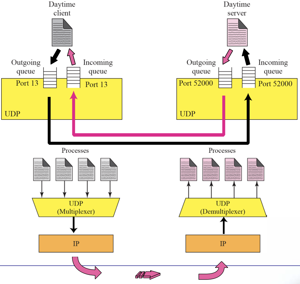
UDP Applications
UDP meets almost none of the criteria for a reliable transport-layer protocol, UDP is preferable for some application
- The reason is that some services may have some side effects that are either unacceptable or not preferable
- An application designer needs sometimes to compromise to get the optimum
Chapter15 : Transmission Control Protocol [TCP]
TCP Services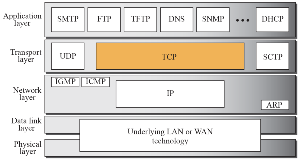
TCP lies between the application layer and network layer, and serves as the intermediary between the application programs and the network operations
Stream Delivery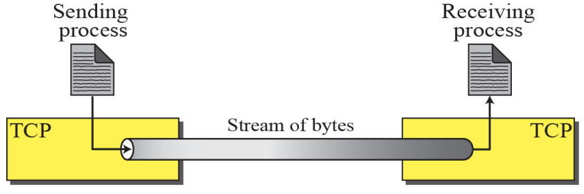
Sending and Receiving Buffers
- TCP is a Stream-Oriented Protocol
- TCP allows the sending process to deliver data as a stream of bytes
- allows the receiving process to obtain data as a stream of bytes
Stream Delivery Service
Sending and Receiving Buffers
- Sending Buffers
- ~ receives data as a stream of bytes from application process using sending buffer
- ~ make data to appropriate segments and transfer to network
- Receiving Buffers
- ~ receives segments using receiving buffer
- ~ reassemble segments to data and send data as a a stream of bytes to application process
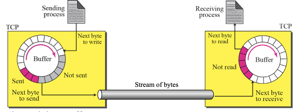
-
Sending and Receiving Buffers
- The sending process and the receiving process may not produce and consume data at the same speed, TCP needs buffers for storage
-
TCP segments
Figure 15.4

Segments
- The IP layer needs to send data in packets, not as a stream of bytes
- At the transport layer, TCP groups a number of bytes together into a packet called a segment
TCP Services
- Stream Delivery Service
- Sending and receiving Buffers
- Segments
- Full-Duplex Service
- Piggybacking
- Connection-Oriented Service
- A virtual Connection (not physical connection)
- Reliable Service
- Reply Acknowledge Packet
TCP vs UDP Communication
TCP has several features
- Numbering System
- Flow Control
- Error Control
- Congestion Control
Numbering System
- TCP keeps track of the segment being transmitted or received using sequence number and acknowledge number, not sequence number (in DLL)
- These number is used for flow and error control
- Byte Number
- When TCP receives of data from the process and store and them in sending buffer and number them
- Sequence Number
- After numbering the bytes, TCP assigns sequence number of to each segment that is being sent
Acknowledgement Number
⚙ The value of the acknowledgment field in a segment defines the number of the next byte a party expects to receive. The acknowledgement number is cumulative.