원시 모델
Three.js 의 원시 모델이란, 런타임에 다양한 인자들로 정의한 3D 모양을 의미한다.
주로 공, 육면체 등으로 3D 그래프를 만드는데 사용한다.
BoxGeomtry 육면체
const width = 8;
const height = 8;
const depth = 8;
const geometry = new THREE.BoxGeometry(width, height, depth);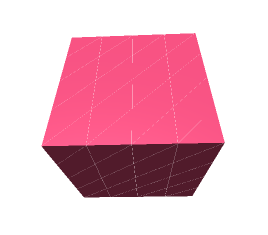
const width = 8;
const height = 8;
const depth = 8;
const widthSegments = 4;
const heightSegments = 4;
const depthSegments = 4;
const geometry = new THREE.BoxGeometry(
    width, height, depth,
    widthSegments, heightSegments, depthSegments);
CircleGeometry 원
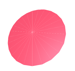
const radius = 7;
const segments = 24;
const geometry = new THREE.CircleGeometry(radius, segments);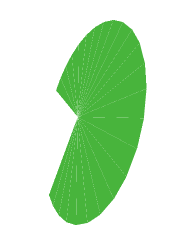
const radius = 7;
const segments = 24;
const thetaStart = Math.PI * 0.25;
const thetaLength = Math.PI * 1.5;
const geometry = new THREE.CircleGeometry(
    radius, segments, thetaStart, thetaLength);
ConGeometry 원뿔
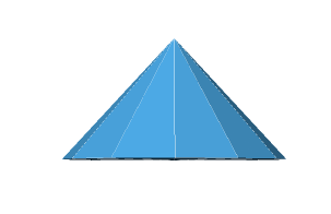
const radius = 6;
const height = 8;
const radialSegments = 16;
const geometry = new THREE.ConeGeometry(radius, height, radialSegments);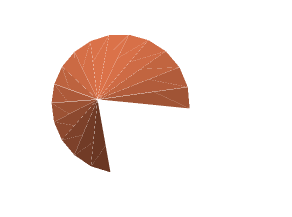
const radius = 6;
const height = 8;
const radialSegments = 16;
const heightSegments = 2;
const openEnded = true;
const thetaStart = Math.PI * 0.25;
const thetaLength = Math.PI * 1.5;
const geometry = new THREE.ConeGeometry(
    radius, height,
    radialSegments, heightSegments,
    openEnded,
    thetaStart, thetaLength);
CylinderGeometry 원통
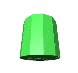
const radiusTop = 4;
const radiusBottom = 4;
const height = 8;
const radialSegments = 12;
const geometry = new THREE.CylinderGeometry(
    radiusTop, radiusBottom, height, radialSegments);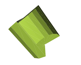
const radiusTop = 4;
const radiusBottom = 4;
const height = 8;
const radialSegments = 12;
const heightSegments = 2;
const openEnded = false;
const thetaStart = Math.PI * 0.25;
const thetaLength = Math.PI * 1.5;
const geometry = new THREE.CylinderGeometry(
radiusTop, radiusBottom, height,
radialSegments, heightSegments,
openEnded,
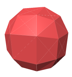
thetaStart, thetaLength);DodecahedronGeometry 십이면체
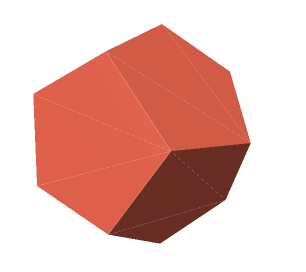
const radius = 7;
const geometry = new THREE.DodecahedronGeometry(radius);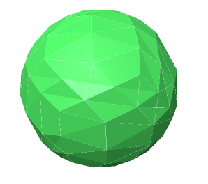
const radius = 7;
const detail = 2;
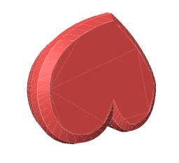
const geometry = new THREE.DodecahedronGeometry(radius, detail);ExtrudeGeometry
사각을 주어 깍아낸 2D 모양이다. 아래는 하트 모양으로 깍아 내린 것이다.
const shape = new THREE.Shape();
const x = -2.5;
const y = -5;
shape.moveTo(x + 2.5, y + 2.5);
shape.bezierCurveTo(x + 2.5, y + 2.5, x + 2, y, x, y);
shape.bezierCurveTo(x - 3, y, x - 3, y + 3.5, x - 3, y + 3.5);
shape.bezierCurveTo(x - 3, y + 5.5, x - 1.5, y + 7.7, x + 2.5, y + 9.5);
shape.bezierCurveTo(x + 6, y + 7.7, x + 8, y + 4.5, x + 8, y + 3.5);
shape.bezierCurveTo(x + 8, y + 3.5, x + 8, y, x + 5, y);
shape.bezierCurveTo(x + 3.5, y, x + 2.5, y + 2.5, x + 2.5, y + 2.5);

const extrudeSettings = {
  steps: 2,
  depth: 2,
  bevelEnabled: true,
  bevelThickness: 1,
  bevelSize: 1,
  bevelSegments: 2,
};

const geometry = THREE.ExtrudeGeometry(shape, extrudeSettings);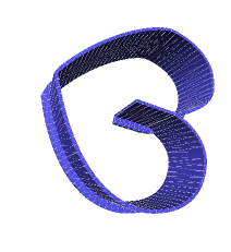
const outline = new THREE.Shape([
  [ -2, -0.1], [  2, -0.1], [ 2,  0.6],
  [1.6,  0.6], [1.6,  0.1], [-2,  0.1],
].map(p => new THREE.Vector2(...p)));

const x = -2.5;
const y = -5;
const shape = new THREE.CurvePath();
const points = [
  [x + 2.5, y + 2.5],
  [x + 2.5, y + 2.5], [x + 2,   y      ], [x,       y      ],
  [x - 3,   y      ], [x - 3,   y + 3.5], [x - 3,   y + 3.5],
  [x - 3,   y + 5.5], [x - 1.5, y + 7.7], [x + 2.5, y + 9.5],
  [x + 6,   y + 7.7], [x + 8,   y + 4.5], [x + 8,   y + 3.5],
  [x + 8,   y + 3.5], [x + 8,   y      ], [x + 5,   y      ],
  [x + 3.5, y      ], [x + 2.5, y + 2.5], [x + 2.5, y + 2.5],
].map(p => new THREE.Vector3(...p, 0));
for (let i = 0; i < points.length; i += 3) {
  shape.add(new THREE.CubicBezierCurve3(...points.slice(i, i + 4)));
}

const extrudeSettings = {
  steps: 100,
  bevelEnabled: false,
  extrudePath: shape,
};

const geometry =  new THREE.ExtrudeGeometry(outline, extrudeSettings);
return geometry;
IcosahedronGeometry 이십면체
const radius = 7;
const geometry = new THREE.IcosahedronGeometry(radius);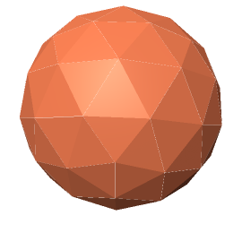
const radius = 7;
const detail = 2;
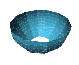
const geometry = new THREE.IcosahedronGeometry(radius, detail);LatheGeometry
선을 회전시키는 것으로 램프, 볼링핀, 초, 와인잔 등을 만들 수 있다.
2D 형태를 점을 사용해 지정하고 축을 따라 세분값과 회전값을 지정해주면 된다.
const points = [];
for (let i = 0; i < 10; ++i) {
  points.push(new THREE.Vector2(Math.sin(i * 0.2) * 3 + 3, (i - 5) * .8));
}
const geometry = new THREE.LatheGeometry(points);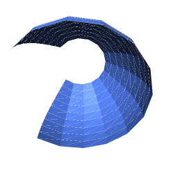
const points = [];
for (let i = 0; i < 10; ++i) {
points.push(new THREE.Vector2(Math.sin(i * 0.2) * 3 + 3, (i - 5) * .8));
}
const segments = 12;
const phiStart = Math.PI * 0.25;
const phiLength = Math.PI * 1.5;
const geometry = new THREE.LatheGeometry(
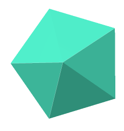
points, segments, phiStart, phiLength);OctahedronGeometry 팔면체
const radius = 7;
const geometry = new THREE.OctahedronGeometry(radius);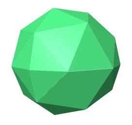
const radius = 7;
const detail = 2;
const geometry = new THREE.OctahedronGeometry(radius, detail);
ParametricGeometry
2D 격자값을 받아 3D 값을 반환하는 함수를 인자로 전달하여 면을 만든다.
function klein(v, u, target) {
u *= Math.PI;
v *= 2 * Math.PI;
u = u * 2;
let x;
let z;
if (u < Math.PI) {
x = 3 * Math.cos(u) * (1 + Math.sin(u)) + (2 * (1 - Math.cos(u) / 2)) * Math.cos(u) * Math.cos(v);
z = -8 * Math.sin(u) - 2 * (1 - Math.cos(u) / 2) * Math.sin(u) * Math.cos(v);
} else {
x = 3 * Math.cos(u) * (1 + Math.sin(u)) + (2 * (1 - Math.cos(u) / 2)) * Math.cos(v + Math.PI);
z = -8 * Math.sin(u);
}
const y = -2 * (1 - Math.cos(u) / 2) * Math.sin(v);
target.set(x, y, z).multiplyScalar(0.75);
}
const slices = 25;
const stacks = 25;
const geometry = new THREE.ParametricGeometry(
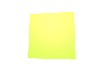
klein, slices, stacks);PlaneGeometry 2D 평면
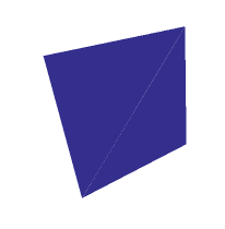
const width = 9;
const height = 9;
const geometry = new THREE.PlaneGeometry(width, height);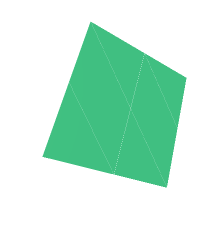
const width = 9;
const height = 9;
const widthSegments = 2;
const heightSegments = 2;
const geometry = new THREE.PlaneGeometry(
    width, height,
    widthSegments, heightSegments);
PolyhedronGeometry
다면체이며, 주어진 3D 점들을 중심으로 삼각형을 구형태로 잇는다.
const verticesOfCube = [
    -1, -1, -1,    1, -1, -1,    1,  1, -1,    -1,  1, -1,
    -1, -1,  1,    1, -1,  1,    1,  1,  1,    -1,  1,  1,
];
const indicesOfFaces = [
    2, 1, 0,    0, 3, 2,
    0, 4, 7,    7, 3, 0,
    0, 1, 5,    5, 4, 0,
    1, 2, 6,    6, 5, 1,
    2, 3, 7,    7, 6, 2,
    4, 5, 6,    6, 7, 4,
];
const radius = 7;
const detail = 2;
const geometry = new THREE.PolyhedronGeometry(
    verticesOfCube, indicesOfFaces, radius, detail);
RingGeometry
중앙이 빈 2D 디스크이다.
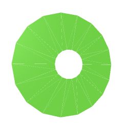
const innerRadius = 2;
const outerRadius = 7;
const thetaSegments = 18;
const geometry = new THREE.RingGeometry(
    innerRadius, outerRadius, thetaSegments);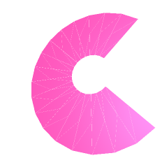
const innerRadius = 2;
const outerRadius = 7;
const thetaSegments = 18;
const phiSegments = 2;
const thetaStart = Math.PI * 0.25;
const thetaLength = Math.PI * 1.5;
const geometry = new THREE.RingGeometry(
    innerRadius, outerRadius,
    thetaSegments, phiSegments,
    thetaStart, thetaLength);
ShapeGeometry
삼각형으로 이루어진 2D 윤곽선이다.
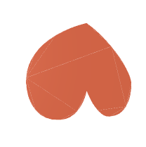
const shape = new THREE.Shape();
const x = -2.5;
const y = -5;
shape.moveTo(x + 2.5, y + 2.5);
shape.bezierCurveTo(x + 2.5, y + 2.5, x + 2, y, x, y);
shape.bezierCurveTo(x - 3, y, x - 3, y + 3.5, x - 3, y + 3.5);
shape.bezierCurveTo(x - 3, y + 5.5, x - 1.5, y + 7.7, x + 2.5, y + 9.5);
shape.bezierCurveTo(x + 6, y + 7.7, x + 8, y + 4.5, x + 8, y + 3.5);
shape.bezierCurveTo(x + 8, y + 3.5, x + 8, y, x + 5, y);
shape.bezierCurveTo(x + 3.5, y, x + 2.5, y + 2.5, x + 2.5, y + 2.5);
const geometry = new THREE.ShapeGeometry(shape);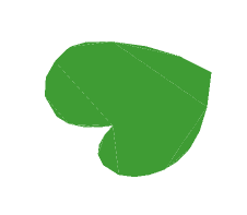
const shape = new THREE.Shape();
const x = -2.5;
const y = -5;
shape.moveTo(x + 2.5, y + 2.5);
shape.bezierCurveTo(x + 2.5, y + 2.5, x + 2, y, x, y);
shape.bezierCurveTo(x - 3, y, x - 3, y + 3.5, x - 3, y + 3.5);
shape.bezierCurveTo(x - 3, y + 5.5, x - 1.5, y + 7.7, x + 2.5, y + 9.5);
shape.bezierCurveTo(x + 6, y + 7.7, x + 8, y + 4.5, x + 8, y + 3.5);
shape.bezierCurveTo(x + 8, y + 3.5, x + 8, y, x + 5, y);
shape.bezierCurveTo(x + 3.5, y, x + 2.5, y + 2.5, x + 2.5, y + 2.5);
const curveSegments = 5;

const geometry = new THREE.ShapeGeometry(shape, curveSegments);
SphereGeometry
구이다.
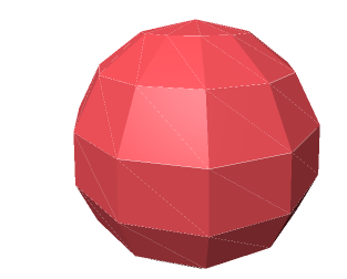
const radius = 7;
const widthSegments = 12;
const heightSegments = 8;
const geometry = new THREE.SphereGeometry(radius, widthSegments, heightSegments);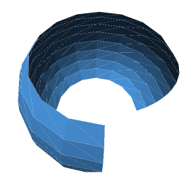
const radius = 7;
const widthSegments = 12;
const heightSegments = 8;
const phiStart = Math.PI * 0.25;
const phiLength = Math.PI * 1.5;
const thetaStart = Math.PI * 0.25;
const thetaLength = Math.PI * 0.5;
const geometry = new THREE.SphereGeometry(
radius,
widthSegments, heightSegments,
phiStart, phiLength,
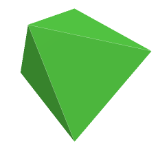
thetaStart, thetaLength);TetrahedronGeometry 사면체
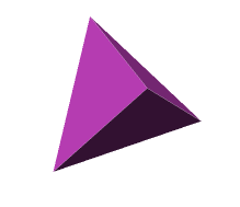
const radius = 7;
const geometry = new THREE.TetrahedronGeometry(radius);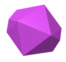
const radius = 7;
const detail = 2;
const geometry = new THREE.TetrahedronGeometry(radius, detail);
TextGeometry
3D 폰트와 문자열로 만든 3D 텍스트다.

const loader = new THREE.FontLoader();

loader.load('../resources/threejs/fonts/helvetiker_regular.typeface.json', (font) => {
  const text = 'three.js';
three.js

  const geometry = new THREE.TextGeometry(text, {
    font: font,
    size: 3,
    height: 0.2,
    curveSegments: 12,
    bevelEnabled: true,
    bevelThickness: 0.15,
    bevelSize: 0.3,
    bevelSegments: 5,

  });
  ...
});
TorusGeometry 원환체, 도넛
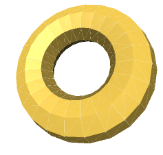
const radius = 5;
const tubeRadius = 2;
const radialSegments = 8;
const tubularSegments = 24;
const geometry = new THREE.TorusGeometry(
radius, tubeRadius,
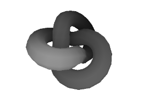
radialSegments, tubularSegments);TorusKnotGeometry 원한체 매듭
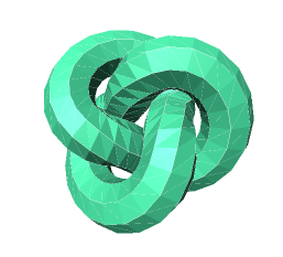
const radius = 3.5;
const tubeRadius = 1.5;
const radialSegments = 8;
const tubularSegments = 64;
const p = 2;
const q = 3;
const geometry = new THREE.TorusKnotGeometry(
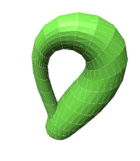
radius, tubeRadius, tubularSegments, radialSegments, p, q);TubeGeometry
패스를 따라 이어진 원이다.
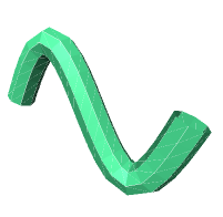
class CustomSinCurve extends THREE.Curve {
  constructor(scale) {
    super();
    this.scale = scale;
  }
  getPoint(t) {
    const tx = t * 3 - 1.5;
    const ty = Math.sin(2 * Math.PI * t);
    const tz = 0;
    return new THREE.Vector3(tx, ty, tz).multiplyScalar(this.scale);
  }
}

const path = new CustomSinCurve(4);
const tubularSegments = 20;
const radius = 1;
const radialSegments = 8;
const closed = false;
const geometry = new THREE.TubeGeometry(
    path, tubularSegments, radius, radialSegments, closed);
EdgesGeometry
geometry 를 받는 객체로, 각 면 사이의 모서리를 표시한다.
이를 사용할 경우 표면의 선들이 사라지는데 thresholdAngle 값을 조정하여 확인해보자.
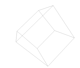
const size = 8;
const widthSegments = 2;
const heightSegments = 2;
const depthSegments = 2;
const boxGeometry = new THREE.BoxGeometry(
    size, size, size,
    widthSegments, heightSegments, depthSegments);
const geometry = new THREE.EdgesGeometry(boxGeometry);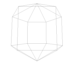
const radius = 7;
const widthSegments = 6;
const heightSegments = 3;
const sphereGeometry = new THREE.SphereGeometry(
    radius, widthSegments, heightSegments);
const thresholdAngle =   1;
const geometry = new THREE.EdgesGeometry(sphereGeometry, thresholdAngle);
WireframeGeometry
geometry 모서리 하나당 하나의 선분을 가진 geometry 를 생성한다.
삼각형이면 3개의 점으로 만든다.
wireframe: true 라는 옵션이 있기는 하지만, 이를 이용 시 삼각형을 만들면 출력되는 건 선 하나 뿐일 것이다.
삼각형 geometry 를 WireframeGeometry 에 넘겨주면 6개의 점과 3개의 선분을 가진 새 geometry 를 생성한다.
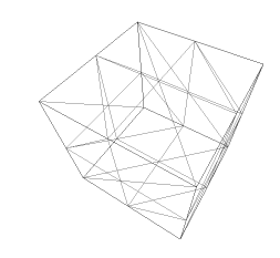
const size = 8;
const widthSegments = 2;
const heightSegments = 2;
const depthSegments = 2;
const geometry = new THREE.WireframeGeometry(
    new THREE.BoxGeometry(
      size, size, size,
      widthSegments, heightSegments, depthSegments));
각 원시 모델로 예제를 만들어보자.
먼저 배경색을 지정한다.
const scene = new THREE.Scene();
scene.background = new THREE.color(0xAAAAAA);
옅은 회색으로 배경을 칠한다.
모든 물체를 봐야하니 카메라도 수정하자.
//const fov = 75;
const fov = 40;
const aspect = 2;  // the canvas default
const near = 0.1;
//const far = 5;
const far = 1000;
const camera = new THREE.PerspectiveCamera(fov, aspect, near, far);
//camera.position.z = 2;
camera.position.z = 120;
다음으로 x, y 좌표와 Object3D 를 매개변수로 받아 씬에 추가하는 addObject 함수를 만든다.
const objects = [];
const spread = 15;

function addObject(x, y, obj) {
  obj.position.x = x * spread;
  obj.position.y = y * spread;

  scene.add(obj);
  objects.push(obj);
}
물체를 무작위로 채색하는 함수도 만든다.
hue, 채도, 명도로 색을 지정하는 Color 기능을 활용하자.
hue: 0 ~ 1까지의 색상값을 고리 모양으로 배치한 것으로, 12시는 빨강, 4시는 녹색, 8시는 파랑이다.saturation(채도): 이 역시 0 ~ 1 이며, 0은 옅고 1은 가장 진하다.luminance(명도): 0.0은 검정, 1.0은 하양으로, 0.5가 가장 색이 풍부하다.
function createMaterial() {
 const material = new THREE.MeshPhongMaterial({
   side: THREE.DoubleSide,
 });

  const hue = Math.random();
  const saturation = 1;
  const luminance = .5;
  material.color.setHSL(hue, saturation, luminance);

  return material;
}
material 에 side : THREE.DoubleSide 옵션을 지정했다.
이는 양면 모두 렌더링하라고 알려주는 것이다.
구나 정육면체는 안쪽은 안보이니 렌더링할 필요가 없지만, PlaneGeometry 나 ShapeGeometry 등 안쪽 면이 없는 물체는 side : THREE.DoubleSide 옵션을 설정하지 않으면 반대편에서는 물체가 사라진 것처럼 보인다.
중요한 것은 side : THREE.DoubleSide 옵션은 렌더링 속도에 영향을 미친다. 가능한한 필요한 물체만 지정하는 것이 좋다.
다음으로 addSolidGeometry 함수를 만든다.
이 함수는 geometry 와 앞서 만든 createMaterial 함수로 무작위 색칠한 물체를 만들어 addObject 함수로 씬에 추가한다.
function addSolidGeometry(x, y, geometry) {
  const mesh = new THREE.Mesh(geometry, createMeterial());
  addObject(x, y, mesh);
}
이제 주요 원시모델을 생성해보자.
예로 정육면체를 만든다고 가정하자.
{
  const width = 8;
  const height = 8;
  const depth = 8;
  addSolidGeometry(-2, 2, new THREE.BoxGeometry(width, height, depth));
}
몇몇 예외가 보이는데, 가장 두드러진 것은 TextGeometry 이다.
이는 mesh 를 생성하기 위해 3D 폰트 데이터를 필요로 하는데, 이 데이터는 비동기 로드기 때문에 기다려야 한다.
폰트 로드 과정을 프로미스화하면 이 과정이 쉬운데, 먼저 FontLoader 를 생성하고, Promise를 반환하는 loadFont 함수로 요청을 Promise 로 감싼다. 그리고 doit 비동기 함수를 만들어 await 키워드로 폰트를 로드한 후, geometry 를 만들어 addObject 함수로 씬에 추가한다.
{
 const loader = new THREE.FontLoader();
  // promise font loading
  function loadFont(url) {
    return new Promise((resolve, reject) => {
      loader.load(url, resolve, undefined, reject);
    });
  }

  async function doit() {
    const font await loadFont('resources/threejs/fonts/helvetiker_regular.typeface.json');
    const geometry = new THREE.TextGeometry('three.js', {
      font: font,
      size: 3.0,
      height: .2,
      curveSegments: 12,
      bevelEnabeld: true,
      bevelThickness: 0.15,
      bevelSize: .3,
      bevelSegments: 5,
    });
    const mesh = new THREE.Mesh(geometry, createMaterial());
    geometry.computeBoundingBox();
    geometry.boundingBox.getCenter(mesh.position).multiplyScalar(-1);

    const parent = new THREE.Object3D();
    parent.add(mesh);

    addObject(-1, -1, parent);
  }
  doit();
}
다른 차이점은 Three.js 의 텍스트는 중앙을 중심으로 돌지 않는다.
기본 회전축은 왼쪽 모서리로, geometry 의 bounding box(경계 좌표)를 계산해 달라고 요청하고 getCetner 메소드의 해당 mesh 의 위치값 계산을 넘겨주어야 중앙을 중심으로 돈다.
이러면 getCenter 메소드는 넘겨받은 위치값의 중앙 좌표값을 자신의 위치값으로 복사한다.
그리고 변경된 위치값 객체를 반환하는데, 이 객체의 multiplyScalar(-1) 메소드로 전체 텍스트의 회전 중심이 텍스트의 중앙에 오도록 조정할 수 있다.
이대로 addSolidGeometry 함수를 호출하면 위치값을 재할당해 버릴 것이다. 그러니 대신 Object3D 를 하나 만들어 텍스트를 감싼다.
addSolidGeometry 를 그냥 사용하면 왼쪽처럼 회전축이 빗나간다.
다른 예외는 2개의 선을 기반으로 한 EdgesGeometry 와 WireframeGeometry 이다.
addSolidGeometry 함수 대신 아래와 같이 addLineGeometry 함수를 호출했다.
function addLineGeometry(x, y, geometry) {
  const material = new THREE.LineBasicMaterial({color: 0x000000});
  const mesh = new THREE.LineSegments(geometry, material);
  addObject(x, y, mesh);
이 함수는 검은 LineBasicMaterial 을 만들고 이를 기반으로 LineSegments 를 만든다.
LineSegments 는 Mesh 의 자식 객체로, Three.js 의 선분 렌더링을 도와주는 객체이다.
패턴이 어려운 클래스로는 PointMaterial 과 Points 클래스인데, Points 는 Geometry 나 BufferGeometry 를 매개변수로 받는 점에 LineSegments 와 비슷하나, 선 대신 각 정점에 점을 그린다는 점이 다르다.
또 점의 크기를 지정하는 size 도 PointsMaterial 에 함께 주어야 한다.
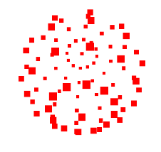
const radius = 7;
const widthSegments = 12;
const heightSegments = 8;
const geometry = new THREE.SphereGeometry(radius, widthSegments, heightSegments);
const material = new THREE.PointsMaterial({
  color: 'red',
  size: 0.2,	// 글로벌 단위
});
const points = new THREE.Points(geometry, material);
scene.add(points);
sizeAttenuation 을 false 로 지정하면 카메라로부터의 거리에 상관없이 점 크기가 일정하게 보인다.
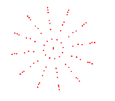
const material = new THREE.PointsMaterial({
color: 'red',
sizeAttenuation: false,
size: 3, // 픽셀
// size: 0.2, // 글로벌 단위
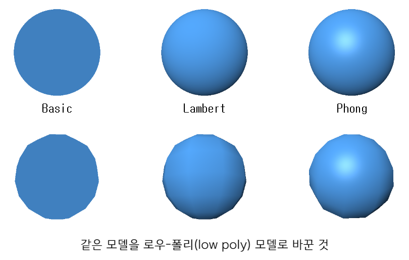
});또 하나는 물체 대부분이 세분값에 대한 설정이 다양한 것이다.
다음과 같이 매개변수로 구체를 구현한 것이다.
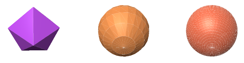
첫 번째는 둘레 5와 높이 3, 둘 째는 24 x 10, 240면, 마지막 구체는 50x50 으로 2500면을 구현했다.
많이 분할할수록 좋아보이나, 선과 플랫 쉐이딩만 제거해도 아래와 같다.
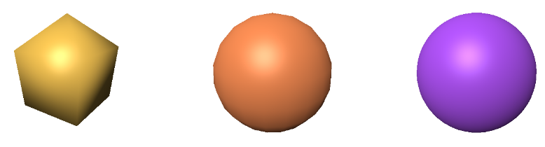
구체 하나에 100000개의 삼각형으로 구체를 만드는 것은 나쁜 것은 아니지만 1초에 60프레임을 렌더링해야 하니, 많은 삼각형을 렌더링해야 한다.
선택이 쉬운 경우도 있는데 예로 평면을 분할한다고 해보자.
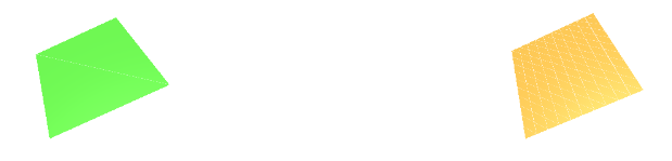
왼쪽은 2 삼각형이고, 오른쪽은 200 삼각형이다.
구체와 다르게 평면은 퀄리티 저하가 없다.
그러니 상황에 따른 적절한 값이 필요하다.
Three.js 의 씬 그래프
Three.js 은 씬 그래프가 중요한데, 계층 구조는 다음과 같다.
가장 쉬운 예로 태양계, 태양, 지구, 달이 적당한 예이다.
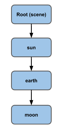
태양 - 지구 - 달 순으로 각 중심에 공전한다.
위와 같은 구체를 구체해보자.
// 회전값을 업데이트할 객체들
const objects = [];

// 하나의 geometry 로 모든 태양, 지구, 달을 생성
const radius = 1;
const widthSegments = 6;
const heightSegments = 6;
const sphereGeometry = new THREE.SphereGeometry(
  radius, widthSegments, heightSegments);

const sunMaterial = new THREE.MeshPhongMaterial({emissive: 0xFFFF00});
const sunMesh = new THREE.Mesh(sphereGeometry, sunMaterial);
sunMesh.scale.set(5, 5, 5);	// 태양의 크기를 키움
scene.add(sunMesh);
objects.push(sunMesh);
예제에선 로우폴리 구체를 사용한다.
같은 구체를 재활용할 것이므로 태양의 mesh 를 5배로 설정해준다.
다음으론 MeshPhongMaterial 의 emissive(방사성) 속성을 노랑으로 지정한다. emissive 속성은 빛을 반사하지 않는 표면 색으로, 광원에 색이 더 진해진다.
씬 가운데 단방향 조명도 하나 넣는다.
{
  const color = 0xFFFFFF;
  const intensity = 3;
  const light = new THREE.PointLight(color, intensity);
  scene.add(light);
}
카메라를 중점 바로 위에 내려다 보게 한다.
시점을 바꾸는 lookAt 메소드를 활용하여 카메라가 넘겨받은 좌표를 바라보게끔 회전시켜준다.
하지만 이전에 먼저 카메라에 어떤 방향이 위인지 알려줘야한다.
대부분의 경우 양의 y 방향을 설정하지만 위에서 아래로 내려다 보니, 양의 z 방향을 해야한다.
const camera = new THREE.PerspectiveCamera(fov, aspect, near, far);
camera.position.set(0, 50, 0);
camera.up.set(0, 0, 1);
camera.lookAt(0, 0, 0);
렌더링 루프에서 objects 배열의 모든 객체를 회전시켜주자.
objects.forEach((obj) => {
  obj.rotation.y = time;
});
sunMesh 를 objects 배열 안에 넣었으니 태양 모델이 회전하는 것을 확인할 수 있다.
다음으로 지구를 추가한다.
const earthMaterial = new THREE.MeshPhongMaterial({color: 0x2233FF, emissive: 0x112244});
const earthMesh = new THREE.Mesh(sphereGeometry, earthMaterial);
earthMesh.position.x = 10;
scene.add(earthMesh);
objects.push(earthMesh);
지구는 파란색을 이용했다.
그리고 이전의 sphereGeometry 와 earthMaterial 을 이용해 earthMesh 를 만들고, 태양의 10칸 옆에 위치했다.
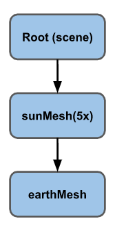
하지만 지구가 태양의 주위로 돌지는 않는다.
지구를 바로 씬에 추가하는 대신, 태양의 자식으로 추가해보자.
// scene.add(earthMesh);
sunMesh.add(earthMesh);
이상한 점은 지구와 태양의 크기가 같고 너무 떨어져있다.
이전에 sunMesh 를 만들 때 sunMesh.scale.set(5, 5, 5) 라는 코드로 크기를 5배 설정했는데, 이는 sunMesh 의 지역 공간 자체를 5배 키우는 것으로 지구도 동일하게 적용된 것이다.
이를 해결하기 위해 빈 씬 그래프 요소를 하나 추가한다.
그리고 태양과 지구 둘 다 이 요소의 자식으로 추가한다.
const solarSystem = new THREE.Object3D();
scene.add(solarSystem);
objects.push(solarSystem);

const sunMaterial = new THREE.MeshPhongMaterial({emissive: 0xFFFF00});
const sunMesh = new THREE.Mesh(sphereGeometry, sunMaterial);
sunMesh.scale.set(5, 5, 5);
//scene.add(sunMesh);
solarSystem.add(sunMesh);
objects.push(sunMesh);

const earthMaterial = new THREE.MeshPhongMaterial({color: 0x2233FF, emissive: 0x112244});
const earthMesh = new THREE.Mesh(sphereGeometry, earthMaterial);
earthMesh.position.x = 10;
//sunMesh.add(earthMesh);
solarSystem.add(earthMesh);
objects.push(earthMesh);
Object3D 를 생성했는데, 그저 하나의 빈 지역 공간인 셈이다.
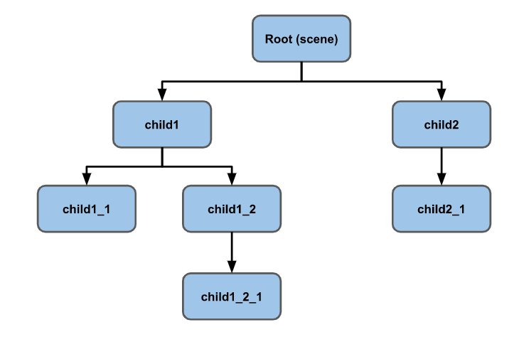
이제 씬 그래프는 다음과 같다.
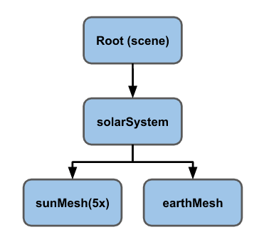
sunMesh 와 earthMesh 는 solarSystem 의 자식이며, 세 객체는 각각 회전한다.
이제 earthMesh는 sunMesh 의 자식이 아니므로 5배 커지지도 않았다.
같은 패턴으로 달도 추가해보자.
const earthOrbit = new THREE.Object3D();
earthOrbit.position.x = 10;
solarSystem.add(earthOrbit);
objects.push(earthOrbit);

const earthMaterial = new THREE.MeshPhongMaterial({color: 0x2233FF, emissive: 0x112244});
const earthMesh = new THREE.Mesh(sphereGeometry, earthMaterial);
//solarSystem.add(earthMesh);
earthOrbit.add(earthMesh);
objects.push(earthMesh);

const moonOrbit = new THREE.Object3D();
moonOrbit.position.x = 2;
earthOrbit.add(moonOrbit);

const moonMaterial = new THREE.MeshPhongMaterial({color: 0x888888, emissive: 0x222222});
const moonMesh = new THREE.Mesh(sphereGeometry, moonMaterial);
moonMesh.scale.set(.5, .5, .5);
moonOrbit.add(moonMesh);
objects.push(moonMesh);
이전처럼 Object3D 를 이용해 earthOrbit 지역 공간을 만들고 거기에 earthMesh 와 moonMesh 를 추가했다.
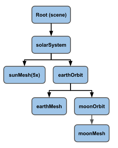
결과물이다.
이처럼 복잡한 연산은 하나도 없으며 모두 씬 그래프에게 맡긴 것 뿐이다.
때론 시각화에도 도움이 되는데 여러 헬퍼 클래스 중 AxesHelper 는 지역 X, Y, Z 축을 표시해준다.
objects.forEach((node) => {
  const axes = new THREE.AxesHelper();
  axes.material.depthTest = false;
  axes.renderOrder = 1;
  node.add(axes);
});
축이 내부에 있어도 전부 보이길 원하니 depthTest 를 false 로 설정한다. 이러면 어느 물체든 뒤에 요소를 그릴지 말지 검사하는 과정을 생략하니 어떤 방향에서도 볼 수 있다.
그리고 renderOrder 를 1로 설정해 구체를 전부 렌더링한 후 축을 렌더링하도록 한다. 그렇지 않으면 구체가 축을 그린 후 구체가 그려져 보이지 않을 수 있다.
x축(빨강), z축(파랑), y축(초록)을 볼 수 있다.
그래도 구별이 어려운데, 간단한 컨트롤 패널을 만들자.
동시에 다른 헬퍼 클래스인 GridHelper 도 추가해본다.
이는 X, Z 축으로 2D 격자를 만드는 클래스로 기본 10x10 칸이다.
또 유명한 dat.GUI 도 사용한다. 이는 라이브러리로, 객체와 속성 이름을 받아 UI로 조정할 수 있게 해준다.
/*
// add an AxesHelper to each node
objects.forEach((node) => {
  const axes = new THREE.AxesHelper();
  axes.material.depthTest = false;
  axes.renderOrder = 1;
  node.add(axes);
});
*/
function makeAxisGrid(node, label, units) {
  const helper = new AxisGridHelper(node, units);
  gui.add(helper, 'visible').name(label);
}

makeAxisGrid(solarSystem, 'solarSystem', 25);
makeAxisGrid(sunMesh, 'sunMesh');
makeAxisGrid(earthOrbit, 'earthOrbit');
makeAxisGrid(earthMesh, 'earthMesh');
makeAxisGrid(moonMesh, 'moonMesh');
makeAxisGrid 함수는 나중에 만들 AxisGridHelper 를 생성하여 dat.GUI 에 붙이는 역할을 한다.
체크박스만 만들 것이므로 boolean 타입으로 속성을 지정해준다.
또 하나의 속성이 바뀔 때 축과 격자가 동시에 나타나고 사라지게 할 것이니 세터/세터가 있는 간단한 클래스를 만든다.
/*
축과 격자를 동시에 켜고 끈다.
dat.GUI 가 체크박스를 만들게 하려면 boolean 타입의 속성을
지정해줘야 하므로, 'visible' 속성에 게터/세터 를 지정해
dat.GUI가 이 속성을 바라보게 한다.
*/
class AxisGridHelper {
  constructor(node, units = 10) {
    const axes = new THREE.AxesHelper();
    axes.material.depthTest = false;
    axes.renderOrder = 2;	// 격자 다음으로 렌더링
    node.add(axes);

    const grid = new THREE.GridHelper(units, units);
    grid.material.depthTest = false;
    grid.renderOrder = 1;
    node.add(grid);

    this.grid = grid;
    this.axes = axes;
    this.visible = false;
  }
  get visible() {
    return this._visible;
  }
  set visible(v) {
    this._visible = v;
    this.grid.visible = v;
    this.axes.visible = v;
  }
}
solarSystem 을 체크하면 지구가 정확히 중앙에서 10칸 떨어진 것을 확인할 수 있다. 지구가 solarSystem 지역 공간 안에 있는 것도 확인할 수 있다.
씬 그래프의 다른 예로는 자동차를 들 수 있다.
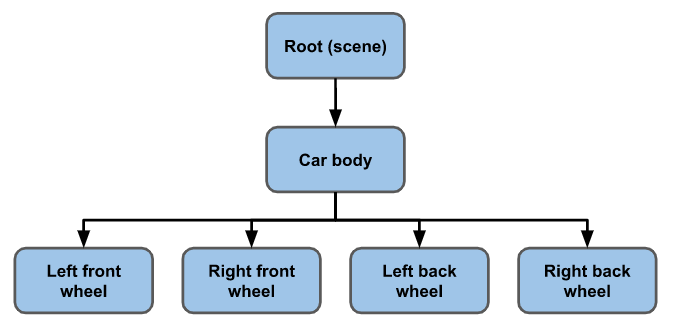
차체(Car body)를 움직이면 바퀴도 같이 움직인다.
차체가 바퀴와는 별도로 튀게 하려면 차체와 바퀴를 하나의 차체 프레임 요소의 자식으로 설정할 수 있다.
다음은 인간형 캐릭터의 예이다.
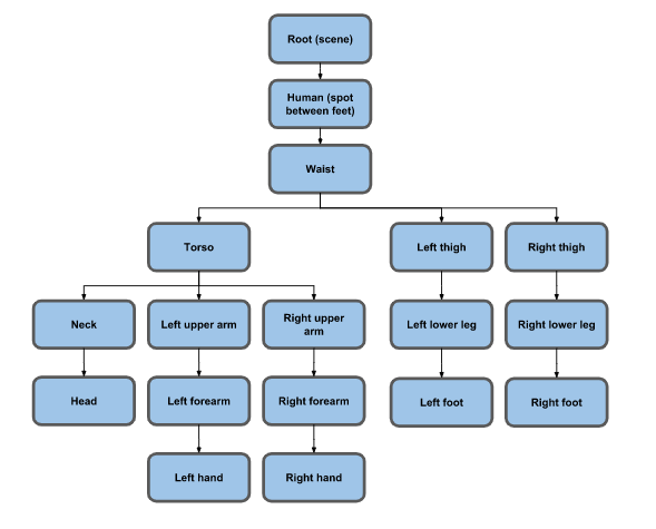
더 복잡하지만 손가락이나 얼굴, 턱, 눈 등으로 세밀히 나누면 더 많아질 것이다.
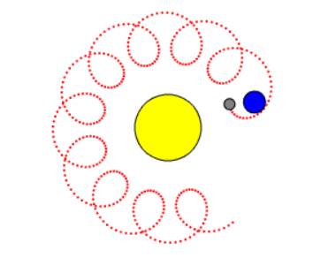
적당한 씬 그래프로 탱크를 구현해보자.
아래는 씬 그래프이며 mesh 는 녹색, Object3D 는 청색, 광원은 갈색, 카메라는 보라색으로 칠했다.
하나의 카메라는 씬 그래프에 포함하지 않는다.
탱크가 조준할 목표를 만들기 위해 earthOrbit 과 유사한 targetOrbit 을 만든다. 그리고 상대 좌표를 넘겨줄 targetElevation 을 만들어 targetOrbit 의 자식으로 추가한 뒤 또 다른 targetBob 을 만들어 targetElevation 의 자식으로 추가한다.
이 targetBob 은 위아래 보빙(몸을 숙이는 동작)하는 역할을 한다.
마지막으로 색이 바뀌는 동시에 회전할 targetMesh 육면체도 만든다.
// 움직이는 목표
targetOrbit.rotation.y = time * .27;
targetBob.position.y = Math.sin(time * 2) * 4;
targetMesh.rotation.x = time * 7;
targetMesh.rotation.y = time * 13;
targetMaterial.emissive.setHSL(time * 10 % 1, 1, .25);
targetMaterial.color.setHSL(time * 10 % 1, 1, .25);
탱크는 tank 라는 이름으로 다른 요소를 감쌀 Object3D 를 하나 생성한다. 예제에서는 커브에 따른 위치값을 반환받을 SplineCurve 를 이용한다. 0.0 은 시작점, 1.0은 커브 끝점으로, 위치를 넘겨주어 탱크의 다음 위치를 정한 뒤(tankPosition), 커브의 다음 값을 받아 탱크가 어디를 볼 지 구한다.(tankTarget) 그리고 구한 값을 Object3D.lookAt 메소드에 넘겨주어 탱크가 바라보도록 한다.
const tankPosition = new THREE.Vector2();
const tankTarget = new THREE.Vector2();

...

// 탱크를 움직임
const tankTime = time * .05;
curve.getPositionAt(tankTime % 1, tankPosition);
curve.getPositionAt((tankTime + 0.01) % 1, tankTarget);
tank.position.set(tankPosition.x, 0, tankPosition.y);
tank.lookAt(tankTarget.x, 0, tankTarget.y);
다음 탱크의 포탑을 탱크의 자식으로 지정해 탱크를 따라 움직이게 한다. 그러고 목표물의 전역 위치값을 구한뒤 Object3D.lookAt 메소드로 포탑이 목표물을 조준하도록 한다.
const targetPosition = new THREE.Vector3();

...

// 목표를 조준
targetMesh.getWorldPosition(targetPosition);
turretPivot.lookAt(targetPosition);
turretCamera 를 turretMesh 의 자식으로 지정해 포탑과 함께 카메라가 움직이게 설정한다. 또 카메라도 목표물을 보게 변경한다.
// 포탑 카메라가 목표물을 바라보도록
turretCamera.lookAt(targetPosition);
targetCameraPivot 은 targetBob 자식으로 지정해 목표물과 돌아다니게 하고, 탱크 뒤를 보도록한다.
이는 targetCamera 가 목표물의 위치에서 살짝 벗어나게 하여, 카메라를 targetBob 의 자식으로 추가한다면 목표물 안에서 탱크를 보게된다.
// targetCameraPivot 이 탱크를 보도록
tank.getWorldPosition(targetPosition);
targetCameraPivot.lookAt(targetPosition);
그 다음 바퀴를 회전시킨다.
wheelMeshes.forEach((obj) => {
  obj.rotation.x = time * 3;
});
카메라를 간단한 설명과 함께 배열로 묶은 뒤,
const cameras = [
  { cam: camera, desc: 'detached camera', },
  { cam: turretCamera, desc: 'on turret looking at target', },
  { cam: targetCamera, desc: 'near target looking at tank', },
  { cam: tankCamera, desc: 'above back of tank', },
];

const infoElem = document.querySelector('#info');
시간에 따라 카메라를 변경한다.
const camera = cameras[time * .25 % cameras.length | 0];
infoElem.textContent = camera.desc;
Three.js 재질(Material)
재질이란, 물체가 씬에 어떻게 나타날지 결정하는 요소로서, 여러가지가 있다.
속성을 정하는 방법은 크게 두 가지로 나뉜다.
하나는 이전처럼 생성자를 호출해 값을 넘겨주는 것이고,
const material = new MeshPhongMaterial({
  color: 0xFF0000,	// 빨강
  flatShading: true
});
다른 하나는 생성 한 뒤에 바꾸는 것이다.
const material = new THREE.MeshPhongMaterial();
material.color.setHSL(0, 1, .5);	// 빨강
material.flatShading = true;
물론 HSL 색상 모델 외에 rgb, hex 등 다양한 방법으로 색 지정이 가능하다.
material.color.set(0x00ffff);
material.color.set(cssString);

material.color.set(someColor);
material.color.setHSL(h, s, l);
material.color.setRGB(r, g, b);
생성시에도 hex 값이나 CSS 문자열도 된다.
const m1 = new THREE.MeshBasicMaterial({color: 0xFF0000});         // 빨강
const m2 = new THREE.MeshBasicMaterial({color: 'red'});            // 빨강
const m3 = new THREE.MeshBasicMaterial({color: '#F00'});           // 빨강
const m4 = new THREE.MeshBasicMaterial({color: 'rgb(255,0,0)'});   // 빨강
const m5 = new THREE.MeshBasicMaterial({color: 'hsl(0,100%,50%)'); // 빨강
이제 Three.js 의 기본 재질을 살펴보자.
MeshBasicMaterial 은 광원의 영향을 받지 않는다.
MEshLamberMaterial 은 정점에만 계산되고
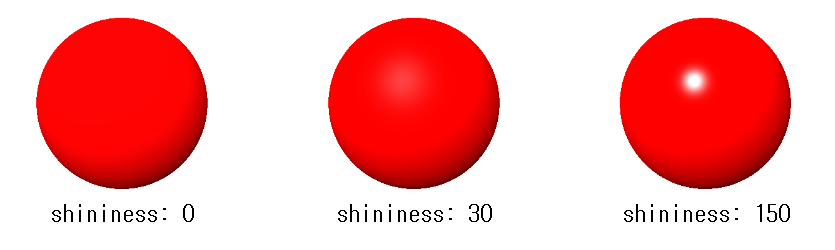
MeshPhongMaterial 은 픽셀 하나하나 광원을 계산한다. 뿐만 아니라 반사점(조명 받을 때 밝은 부분)도 지원한다.
MeshPhongMaterial 의 shininess 속성으로 반사점의 밝기를 조절할 수 있다.
MeshLambertMaterial 이나 MeshPhongMaterial 의 emissive 속성에 색상값을 지정하고 color 속성을 검정으로 하면 MEshBasicMaterial 처럼 입체감이 사라진다.
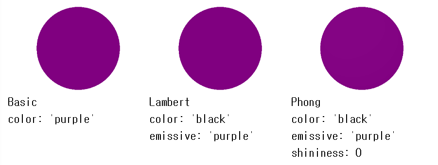
MeshPhongMaterial 로 세 재질을 구현할 수 있지만 분리한 이유는 재질이 정교할 수록 GPU 부담이 커지기 때문이다.
광원 효과가 아예 필요없으면 MeshBasicMaterial 을 사용하자.
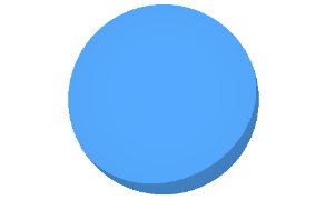
MeshToonMaterial 은 MeshPhongMaterial 과 비슷하지만 MeshToonMaterial 은 그라디언트 맵을 사용한다는 것이다.
그래서 카툰 느낌을 줄 수 있다.
다음으로 볼 두 재질은 물리 기반렌더링을 위한 재질 이다.
Physically Based Rendering 을 줄여서 PBR 이라 하자.
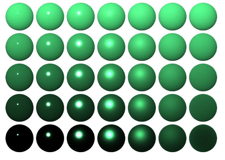
첫 번째는 MeshStandarMaterial 이다.
MeshPhongMaterial 와는 속성이 다르다는 점인데 MeshPhongMaterial 은 shininess 를 사용하지만 이는 roughness 와 metalness 두 가지 속성을 사용한다.
roughness 는 0 ~ 1 까지의 숫자값으로 shininess 의 반대이다.
높은 roughness 를 가진 물체는 매우 번들번들하다.
metalness 는 얼마나 금속성인지 값을 정한다. 0은 아예 금속같지 않고, 1은 완전 금속처럼 보이는 것이다.
아래는 roughness 를 왼쪽에서 오른쪽으로 커지게(0 -> 1)
metalness 를 위에서 아래로 커지게(0 -> 1) 한 것이다.
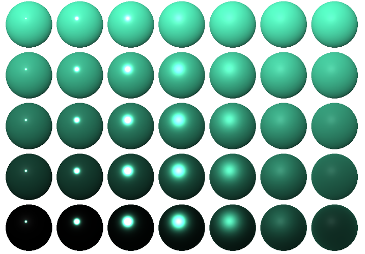
MeshPhysicalMaterial 은 MeshStandarMaterial 과 기본적으로 같지만, 0부터 1까지의 clearcoat 속성으로 표면에 코딩 세기를 설정하고, clearcoatRoughness 속성으로 코팅의 거침 정도를 설정한다는 점이 다르다.
위 예제처럼 roughness 와 metalness 속성을 주고 clearcoat 속성과 clearcoatRoughness 속성을 각각 0.5 씩 값을 주었다.
여태까지 본 재질 성능을 빠른 것부터 나열하면
MEshBasicMaterial → MeshLambertMaterial → MeshPhongMaterial → MeshStandardMaterial → MeshPhysicalMaterial 이다.
상황에 맞는 재질로 코드 최적화에도 신경을 써야한다.
특수한 경우의 세 가지 재질이 있는데, ShadowMaterial 은 그림자로부터 데이터를 가져오는데 사용한다. 이는 나중에 살펴보자.
MeshDepthMaterial 은 각 픽셀의 깊이를 렌더링한다. 마이너스 near 에 위치한 픽셀은 0, 마이너스 far 에 위치한 픽셀은 1로 렌더링한다.
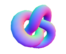
MeshNormalMaterial 은 geometry 의 법선(normals)을 보여준다.
법선 이란 특정 삼각형이나 픽셀의 방향을 의미한다.
카메라 기반으로 렌더링하는데, x축은 빨강, y축은 초록, z축은 파랑이다.
ShaderMaterial 과 RawShaderMaterial 은 재질을 커스텀할 때 사용한다. 전자는 Three.js 의 쉐이더 시스템을 사용하고, 후자는 도움을 받지 않는다. 이는 나중에 다룬다.
재질 속성의 대부분은 Material 클래스에 의해 정의되며 자주사용하는 두 가지 속성만 더 보자.
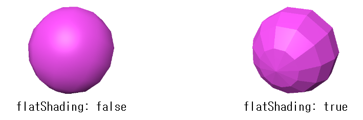
flatShading: 물체를 각지게 표현할지의 여부. 기본값false
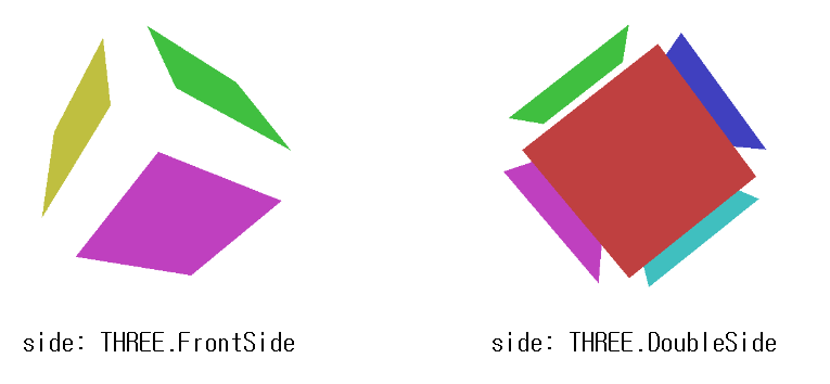
side: 어느 면을 렌더링할지 여부.
기본값은THREE.FrontSide(앞면)다른 값으로는THREE.BackSide와THREE.DoubleSide가 있다.
아래는 앞면과 양면으로 6면을 렌더링한 것이다.
Three.js 텍스처(Textures)
하이, 텍스처
텍스처는 포토샵이나 김프 등으로 만든 이미지다.
예로 다음 이미지를 정육면체에 씌어보자.
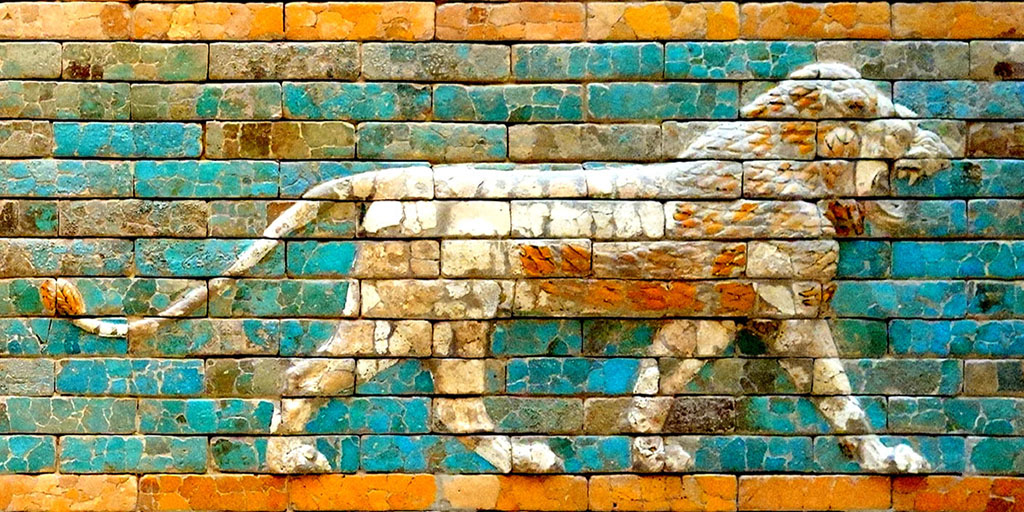
TextureLoader 를 새로 생성 후, 인스턴스의 load 메소드로 이미지 URL 을 넘겨주어 호출하고, 반환 받은 값을 재질의 map 속성에 지정한다. (color 는 지정하지 않음)
const loader = new THREE.TextureLoader();
const material = new THREE.MeshBasicMaterial({
  // color: 0xFF8844
  map: loader.load("./wall.jpg"),
});
※ MeshBasicMaterial 을 사용하였으니 광원을 사용할 필요는 없다.
육면체 각 면에 다른 첵스처 지정
이번에는 각 면에 다른 텍스처를 넣어보자.
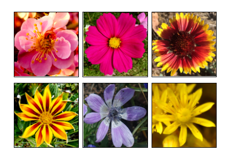
단순히 재질을 6개로 만들어 Mesh 를 생성할 때 배열로 넘겨주기만 하면 된다.
const loader = new THREE.TextureLoader();

// const material = new THREE.MeshBasicMaterial({
//   map: loader.load('resources/images/wall.jpg'),
// });
const materials = [
  new THREE.MeshBasicMaterial({map: loader.load('resources/images/flower-1.jpg')}),
  new THREE.MeshBasicMaterial({map: loader.load('resources/images/flower-2.jpg')}),
  new THREE.MeshBasicMaterial({map: loader.load('resources/images/flower-3.jpg')}),
  new THREE.MeshBasicMaterial({map: loader.load('resources/images/flower-4.jpg')}),
  new THREE.MeshBasicMaterial({map: loader.load('resources/images/flower-5.jpg')}),
  new THREE.MeshBasicMaterial({map: loader.load('resources/images/flower-6.jpg')}),
];
// const cube = new THREE.Mesh(geometry, material);
const cube = new THREE.Mesh(geometry, materials);
주의할 점은 모든 geometry 가 재질을 배열로 받지는 않는다.
BoxGeometry 는 최대 6개, ConeGeometry는 밑면과 뿔 부분에 하나씩 최대 2개 등으로 지정할 수 있다. 다른 경우엔 geometry 를 따로 만들거나, 텍스처의 좌표를 직접 수정해야 한다.
하나의 geometry 에 여러 텍스처를 쓰고 싶다면 보통 텍스처 아틀라스를 사용한다.
이는 여러 이미지로 구성된 하나의 텍스처이다.
텍스처 좌표는 geometry 의 각 정점에 추가된 데이터로, 특정 정점에 텍스처의 어느 부분을 써야할 지 나타낸다.
텍스처 불러오기
간단한 방법
위 예제에서는 대부분 로딩할 때 간단한 메소드를 사용했다.
TextureLoader 를 생성하고, 인스턴스의 load 메소드를 호출했다.
load 메소드는 Texture 객체를 반환한다.
const texture = loader.load('resource/images/flower-1.jpg');알아야 하는 것은 이 메소드는 비동기로 작동한다.
이미지를 완전 불러온 후 텍스처를 업데이트하기까지, 텍스처는 투명하다.
전부 불러오지 않아도 브라우저가 페이지 렌더링을 시작할 것이므로 이는 속도 면에서는 큰 장점이다.
하지만 언제 불러왔는지 알아야할 경우엔 큰 문제가 있다.
텍스처를 불러온 후 처리하기
불러온 후 후처리를 위해 load 메소드는 두 번째 인자로 콜백 함수를 받는다.
이 함수는 전부 불러온 후 호출된다. 예제를 조금 수정해보자.
const loader = new THREE.TextureLoader();
loader.load('resource/images/wall.jpg', (texture) => {
  const material = new THREE.MeshBasicMaterial({
    map: texture,
  });
  const cube = new THREE.Mesh(geometry, material);
  scene.add(cube);
  cubes.push(cube);
});
브라우저 캐시를 비우거나 인터넷 속도가 느리지 않는 한 차이를 느끼긴 어렵지만, 텍스처를 불러온 뒤 렌더링한다.
다수 텍스처를 불러온 후 처리
다수 텍스처를 불러올 경우 LoadingManager 를 사용할 수 있다.
TextureLoader 를 생성할 때 미리 생성한 LoadingManager 의 인스턴스를 인자로 넘겨주고, LoadingManager 인스턴스의 onLoad 속성에 콜백 함수를 설정해 주는 것이다.
const loadManager = new THREE.LoadingManager();
const loader = new THREE.TextureLoader(loadManager);

const materials = [
  new THREE.MeshBasicMaterial({map: loader.load('resources/images/flower-1.jpg')}),
  new THREE.MeshBasicMaterial({map: loader.load('resources/images/flower-2.jpg')}),
  new THREE.MeshBasicMaterial({map: loader.load('resources/images/flower-3.jpg')}),
  new THREE.MeshBasicMaterial({map: loader.load('resources/images/flower-4.jpg')}),
  new THREE.MeshBasicMaterial({map: loader.load('resources/images/flower-5.jpg')}),
  new THREE.MeshBasicMaterial({map: loader.load('resources/images/flower-6.jpg')}),
];

loaderManager.onLoad = () => {
  const cube = new THREE.Mesh(geometry, materials);
  scene.add(cube);
  cubes.push(cube);
};
LoadingManager 의 onProgress 에 콜백 함수를 지정하면 현재 진행 상태를 추적할 수 있다.
일단 HTML 로 프로그래스 바를 만들자.
<body>
  <canvas id="c"></canvas>
  <div id="loading">
    <div class="progress"><div class="progressbar"></div></div>
  </div>
</body>
스타일도 추가한다.
#loading {
    position: fixed;
    top: 0;
    left: 0;
    width: 100%;
    height: 100%;
    display: flex;
    justify-content: center;
    align-items: center;
}
#loading .progress {
    margin: 1.5em;
    border: 1px solid white;
    width: 50vw;
}
#loading .progressbar {
    margin: 2px;
    background: white;
    height: 1em;
    transform-origin: top left;
    transform: scaleX(0);
}
다음으로 onProgress 콜백에 .progressbar 의 X 축 크기를 조정한다.
콜백 함수는 마지막으로 불러오는 자원의 URL, 현재까지 불러온 자원의 수, 총 지원의 수를 매개변수로 받는다.
const loadingElem = document.querySelector('#loading');
const progressBarElem = loadingElem.querySelector('.progressbar');

loadManager.onLoad = () => {
  loadingElem.style.display = 'none';
  const cube = new THREE.Mesh(geometry, materials);
  scene.add(cube);
  cubes.push(cube);
};

loadManager.onProgress = (urlOfLastItemLoaded, itemsLoaded, itemsTotal) => {
  const progress = itemsLoaded / itemsTotal;
  progressBarElem.style.transform = `scaleX(${progress})`;
};
캐시를 비우거나 인터넷 속도가 느리지 않으면 프로그래스 바가 보이지 않을 수도 있다.
다른 도메인에서 텍스처 불러오기
다른 서버의 이미지를 불러오려면 해당 서버가 CORS 헤더를 보내줘야 한다.
이것이 없다면 이미지를 불러오지 않을 것이고, 에러가 발생한다. 그래서 보내는지 확인 절차를 해야한다.
메모리 관리
텍스처는 Three.js 앱에서 메모리를 가장 많이 사용하는 요소 중 하나다.
대체로 너피 * 높이 * 4 * 1.33 바이트의 메모리를 사용한다.
압축은 그다지 중요한 요소가 아니며, 예로 나무 텍스처를 씌우려고 한다.
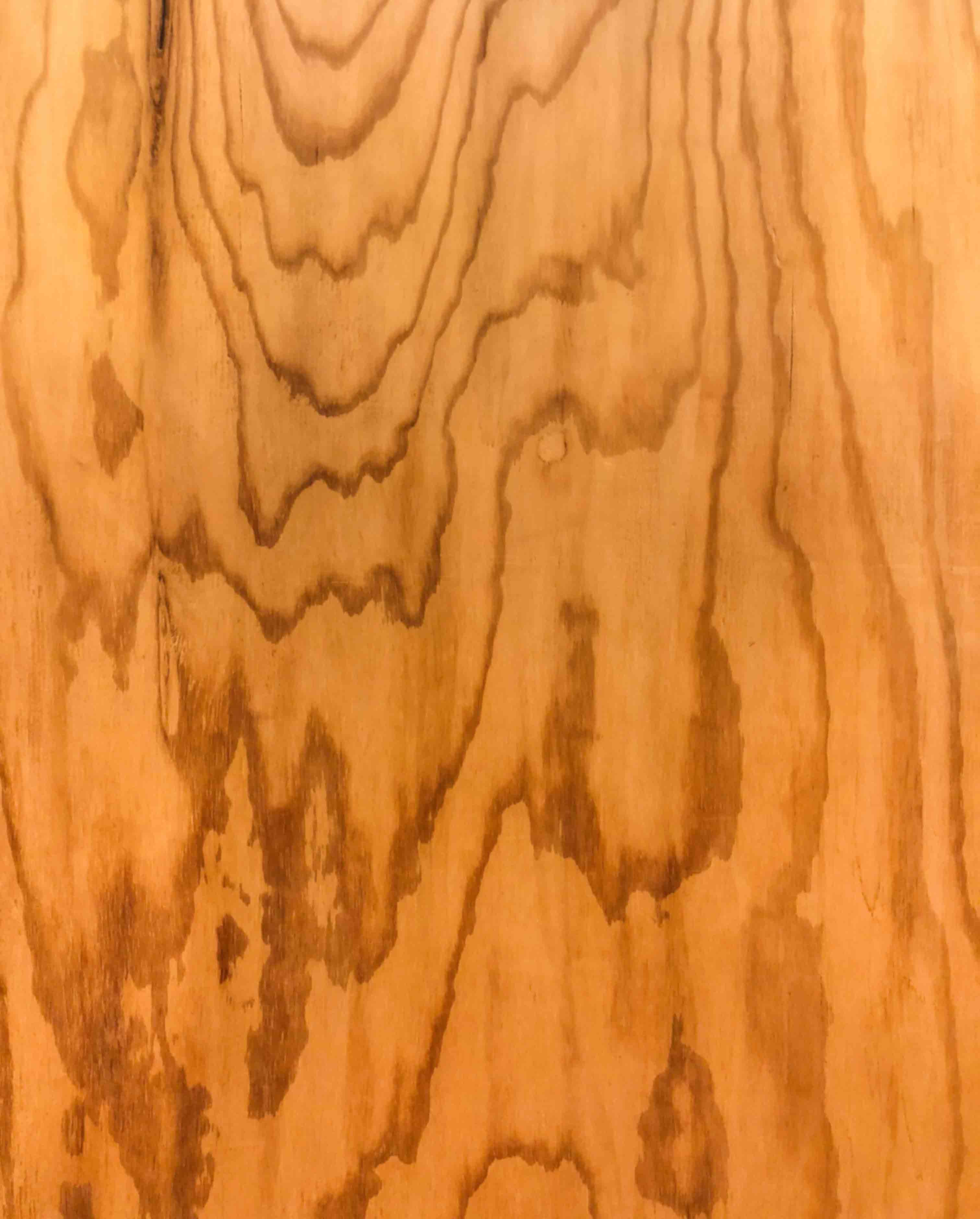
이 이미지는 고 배율로 압축되어 157kb 밖에 안된다.
다운 속도는 바르나, 실제 크기는 3024 x 3761 픽셀인데 위 공식을 적용하면
3024 * 3761 * 4 * 1.33 = 60505764.5약 60메가바이트 메모리를 사용한다. 이런 텍스처가 몇 개만 더 있으면 메모리 부족으로 앱을 사용 못할 수 있다.(OUT_OF_MEMORY)
극단적이긴 하나, 숨겨진 비용을 모두 고려해야 한다.
JPG vs PNG
이는 HTML 도 마찬가지며 JPG는 손실 압축이며 PNG는 비손실 압축으로, 보통 PNG가 용량이 크다. 하지만 PNG는 투명도를 지원한다.
PNG는 비-이미지 데이터인 법선 맵으로 현재로써 가장 적당한 파일 형식이다.
필터링과 Mips
이 16x16 텍스처를
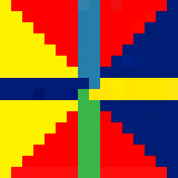
아래 육면체에 적용해보자.
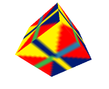
그리고 육면체를 아주 작게 렌더링한다.

잘 안보이니 확대해보자.
GPU 는 아주 작은 육면체를 표현할 때 각 픽셀의 색상은 필터링을 거친다.
포토샵이면 픽셀 평균을 1, 2 픽셀로 결정할 것인데, 이는 무거운 작업이며, GPU는 이 문제를 밉맵(mipmaps)을 사용한다.
밉(mip)은 텍스처의 복사본으로, 축소된 이전 밉보다 반만큼 작다.
1, 2 픽셀 정도로 작으면 GPU는 가장 작거나, 두 번째로 작은 밉을 선택해 텍스처를 적용하기만 하면 된다.
텍스처가 원본보다 클 때와 작을 때의 표현을 설정할 수 있다.
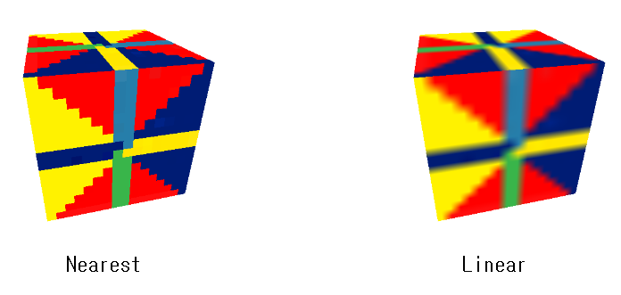
텍스처의 크기가 원본보다 클 때의 필터는 texture.magFilter 속성으로 THREE.NearestFilter 나 THREE.LinearFilter 로 지정해 설정할 수 있다.
NearestFilter 는 가장 가까운 픽셀을 고르는 것이다.
낮은 해당도라면 텍스처가 픽셀화되어 마인크래프트 느낌을 준다.
LinearFilter 는 가장 가까운 4개의 픽셀을 골라 각 픽셀의 실제 거리에 따른 적절한 비율로 섞는 것이다.
텍스처가 원본 크기보다 작을 때의 필터는 texture.minFilter 속성으로 6가지 값 중 하나로 지정할 수 있다.
THREE.NearestFilter: 원본보다 클 때와 마찬가지로 가장 가까운 픽셀 선택THREE.LinearFilter: 원본보다 클 때와 마찬가지로 주변 가까운 픽셀 4개 골라 섞는다.THREE.NearestMipmapNearestFilter: 적절한 밉을 골라 픽셀 하나를 선택한다.THREE.LinearMipmapNearestFilter: 적절한 밉을 골라 픽셀 4개를 골라 섞는다.THREE.LinearMipmapLinearFilter: 두 개의 밉을 골라 각각 픽셀 4개 선택 후 8개의 픽셀을 하나의 픽셀로 혼합한다.
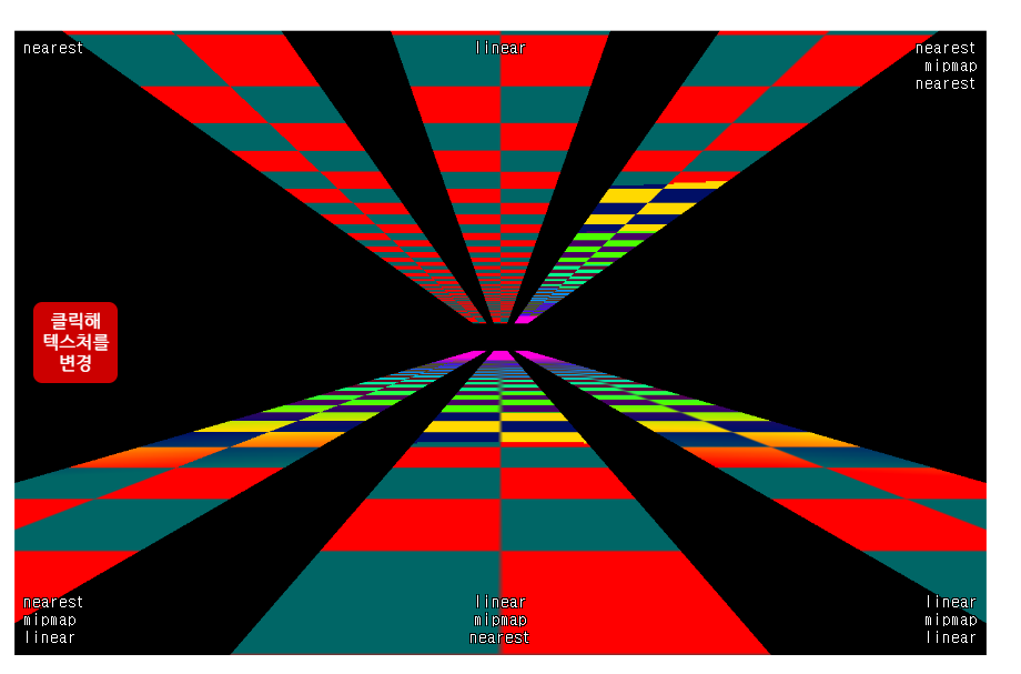
여기서 봐야할 점은 상단 왼쪽과 중앙은 밉을 사용하지 않아 텍스처가 멀수록 픽셀이 깜빡인다.
다른 예제는 표현이 잘되며 그 중 LinearMipmapLinearFilter 가 제일 깔끔하다.
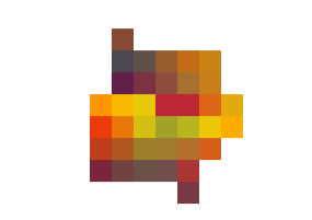
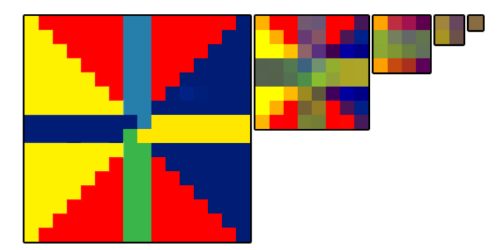
위 예제는 다음의 이미지들을 사용했는데
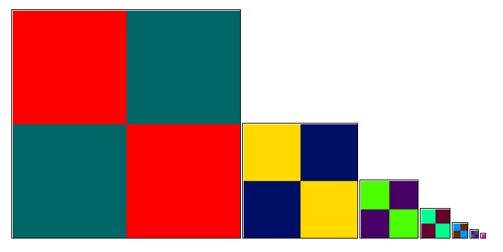
첫 번째가 위 예제이고, 다른 이미지는 밉의 각 단계로 섞었다.
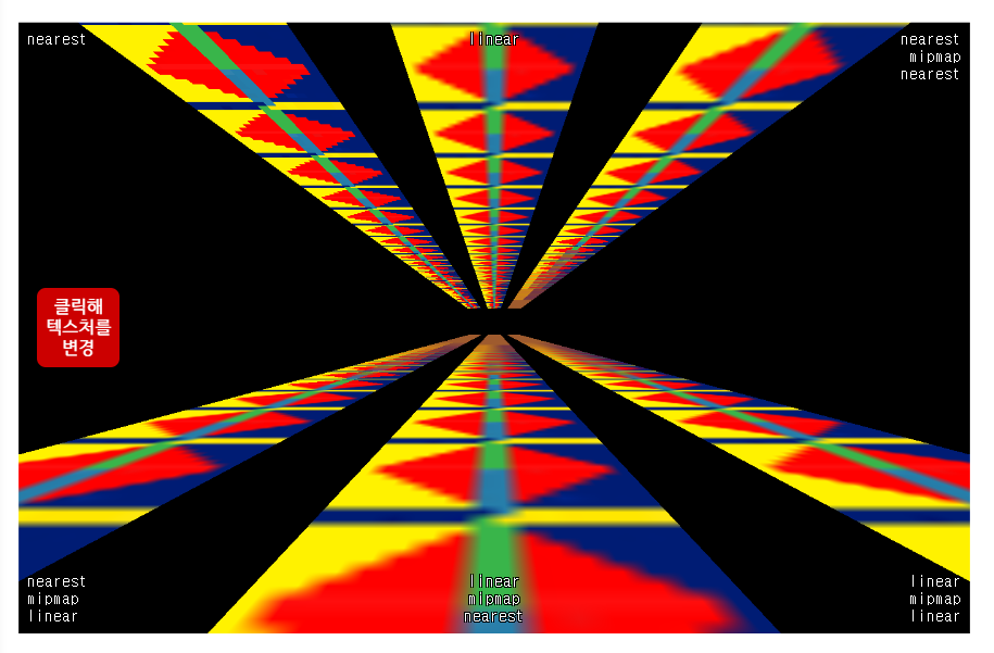
이는 필터의 동작 원리를 이해하기 쉬운데, NearestFilter 와 LinearFilter 는 멀리까지도 첫 번째 밉을 사용한다. 반면 상단 오른족과 하단 중앙은 밉의 경계가 뚜렷하다.
하단 오른쪽이 가장 매끄러운에 항상 이 필터를 사용하지 않는 것도 역시 최적화인데, 큰 성능 차이를 체감하기는 어렵지만, 한 물체에 여러 텍스처가 들어가는 것이 빈번하므로 중요한 요소이다.
텍스처의 반복(repeating), 위치 조절(offseting), 회전(rotating), 래핑(wrapping)
Three.js 는 기본적으로 텍스처를 반복하진 않는다.
반복 여부를 설정하는 2가지 속성이 있는데, 하나는 수평 래핑을 설정하는 wrapS 이고, 다른 하나는 수직 래핑을 설정하는 wrapT 이다.
두 속성은 다음 중 하나로 지정할 수 있다.
THREE.ClampToEdgeWrapping: 텍스처의 가장자리 픽셀을 반복THREE.RepeatWrapping: 텍스처 자체를 반복THREE.MirroredRepeatWrapping: 텍스처 자체를 반복하되, 매번 뒤집음
양 방향 래핑을 키려면 다음과 같이 설정할 수 있다.
someTexture.wrapS = THREE.RepeatWrapping;
someTexture.wrapT = THREE.RepeatWrapping;
반복은 repeat 속성으로 설정할 수 있다.
const timeToRepeatHorizontally = 4;
const timeToRepeatVertically = 2;
someTexture.repeat.set(timeToRepeatHorizontally,
                       timeToRepeatVertically);
텍스처 위치는 offset 속성을 설정해 조절할 수 있다.
텍스처 위치의 단위는 크기와 1:1 로 0 은 그대로, 1은 텍스처 크기만큼 이동한 것이다.
const xOffset = .5;  // 텍스처 너비의 반만큼 이동
const yOffset = .25; // 텍스처 높이의 1/4만큼 이동
someTexture.offset.set(xOffset, yOffset);
회전은 rotation 속성을 라디안 단위로 조절할 수 있다.
center 속성은 회전 중심을 정하며 (0, 0) 과 같이 기준을 설정할 수 있다.
offset 과 같이 텍스트 크기를 기준으로 하기 때문에 (.5, .5) 로 설정하면 텍스처 중앙이다.
someTexture.center.set(.5, .5);
sometexture.rotation = THREE.MathUtils.degToRad(45);
먼저 텍스처를 별도 변수에 담아 나중에 수정할 수 있도록 한다.
const texture = loader.load('resources/images/wall.jpg');
const material = new THREE.MeshBasicMaterial({
  // map: loader.load('resources/images/wall.jpg');
  map: texture,
});
간단한 인터페이스를 만들어 보자.
다시 dat.GUI 를 사용한다.
import { GUI } from '../3rdparty/dat.gui.module.js';이전처럼 헬퍼 클래스도 만들어 각도로 값을 조절하면 알아서 호도 변환하여 저장하게끔 한다.
class DegRadHelper {
  constructor(obj, prop) {
    this.obj = obj;
    this.prop = prop;
  }
  get value() {
    return THREE.MathUtils.radToDeg(this.obj[this.prop]);
  }
  set value(v) {
    this.obj[this.prop] = THREE.MathUtils.degToRad(v);
  }
}
그리고 문자열을 숫자형으로 변환시킬 클래스도 만든다.
dat.GUI 는 값을 문자열로 넘겨주는데, wrapS 나 wrapT 등 enum 값을 지정할 때 숫자형만 받기 때문이다.
class StringToNumberHelper {
  constructor(obj, prop) {
    this.obj = obj;
    this.prop = prop;
  }
  get value() {
    return this.obj[this.prop];
  }
  set value(v) {
    this.obj[this.prop] = parseFloat(v);
  }
}
위 클래스를 이용해 설정값을 조절할 GUI를 만든다.
const wrapModes = {
  'ClampToEdgeWrapping': THREE.ClampToEdgeWrapping,
  'RepeatWrapping': THREE.RepeatWrapping,
  'MirroredRepeatWrapping': THREE.MirroredRepeatWrapping,
};

function updateTexture() {
  texture.needsUpdate = true;
}

const gui = new GUI();
gui.add(new StringToNumberHelper(texture, 'wrapS'), 'value', wrapModes)
  .name('texture.wrapS')
  .onChange(updateTexture);
gui.add(new StringToNumberHelper(texture, 'wrapT'), 'value', wrapModes)
  .name('texture.wrapT')
  .onChange(updateTexture);
gui.add(texture.repeat, 'x', 0, 5, .01).name('texture.repeat.x');
gui.add(texture.repeat, 'y', 0, 5, .01).name('texture.repeat.y');
gui.add(texture.offset, 'x', -2, 2, .01).name('texture.offset.x');
gui.add(texture.offset, 'y', -2, 2, .01).name('texture.offset.y');
gui.add(texture.center, 'x', -.5, 1.5, .01).name('texture.center.x');
gui.add(texture.center, 'y', -.5, 1.5, .01).name('texture.center.y');
gui.add(new DegRadHelper(texture, 'rotation'), 'value', -360, 360)
  .name('texture.rotation');
텍스처의 wrapS 나 wrapT 속성을 변경할 경우 texture.needsUpdate 를 true 로 설정해야 한다.
Three.js 조명
이번엔 다양한 조명을 어떻게 쓸지 알아보자.
먼저 카메라를 설정한다.
const fov = 45;
const aspect = 2;
const near = 0.1;
const far = 100;
const camera = new THREE.PerspectiveCamera(fov, aspect, near, far);
camera.position.set(0, 10, 20);
다음으로 OrbitControls 를 추가한다.
특정 좌표를 중심으로 카메라를 자전 또는 공전하도록 해준다. 별도 모듈이기 때문에 로드해주어야 한다.
import * as THREE from './resources/three/r127/build/three.module.js';
import { OrbitControls } from './resources/threejs/r127/examples/jsm/controls/OrbitControls.js';
이제 OrbitControls 에 카메라와, DOM 이벤트를 감지할 수 있도록 캔버스 요소를 넘겨준다.
const controls = new OrbitControls(camera, canvas);
constrols.target.set(0, 5, 0);
constrols.update();
또한 시점 중점에서 위로 5칸 올려 controls.update 메소드로 OrbitControls 가 새로운 시점을 바라보게 한다.
다음 빛을 받을 무언가를 만들자.
먼저 땅 역할을 할 평면을 만들어 평면에 2x2 픽셀의 체크판 텍스처를 씌운다.

일단 텍스처를 불러온 뒤, 반복하도록 래핑 설정한다.
필터는 NearestFilter, 텍스처가 2x2 픽셀의 체크판이니 repeat 속성을 평면의 반으로 설정하면 체크판의 각 칸이 정확히 1칸이 될 것이다.
const planeSize = 40;

const loader = new THREE.TextureLoader();
const texture = loader.load('resources/images/checker.png');
texture.wrapS = THREE.RepeatWrapping;
texture.wrapT = THREE.RepeatWrapping;
texture.magFilter = RHREE.NearestFilter;
const repeats = planeSize / 2;
texture.repeat.set(repeats, repeats);
그리고 평면 geometry, 평면에 쓸 재질, 장면에 추가할 mesh 를 만든다. 평면은 기본적으로 XY축을 기준으로 하니, XZ 축을 기준으로 하려면 평면을 회전 시켜야 한다.
const planeGeo = new THREE.PlaneGeometry(planeSize, planeSize);
const planeMat = new THREE.MeshPhongMaterial({
  map: texture,
  size: THREE.DoubleSide,
});
const mesh = new THREE.Mesh(planeGeo, planeMat);
mesh.rotation.x = Math.PI * -.5;
scene.add(mesh);
정육면체와 구체도 추가하여 평면까지 총 3개의 물체를 추가한다.
{
  const cubeSize = 4;
  const cubeGeo = new THREE.BoxGeometry(cubeSize, cubeSize, cubeSize);
  const cubeMat = new THREE.MeshPhongMaterial({color: '#8AC'});
  const mesh = new THREE.Mesh(cubeGeo, cubeMat);
  mesh.position.set(cubeSize + 1, cubeSize / 2, 0);
  scene.add(mesh);
}
{
  const sphereRadius = 3;
  const sphereWidthDivisions = 32;
  const sphereHeightDivisions = 16;
  const sphereGeo = new THREE.SphereGeometry(sphereRadius,
                                             sphereWidthDivisions,
                                             sphereHeightDivisions);
  const sphereMat = new THREE.MeshPhongMaterial({color: '#CA8'});
  const mesh = new THREE.Mesh(sphereGeo, sphereMat);
  mesh.position.set(-sphereRadius - 1, sphereRadius + 2, 0);
  scene.add(mesh);
}
빛을 받을 물체를 만들었으니 이제 조명을 만들어보자.
AmbientLight
먼저 AmbientLight(자연광) 을 써보자.
const color = 0xFFFFFF;
const intensity = 1;
const light = new THREE.AmbientLight(color, intensity);
scene.add(light);
이 조명도 dat.GUI 를 사용해 속성을 조정할 수 있도록 만든다.
색상을 조절하려면 간단한 헬퍼 클래스가 필요하니 색상을 변경하며 dat.GUI 에 넘겨주는 역할을 할것이다.
그리고 dat.GUI 가 클래스의 속성으로 지정할 때, 이를 조명에 직접 지정하도록 한다.
class ColorGUIHelper {
  constructor(object, prop) {
    this.object = object;
    this.prop = prop;
  }
  get value() {
    return `#${this.object[this.prop].getHexString()}`;
  }
  set value(hexString) {
    this.object[this.prop].set(hexString);
  }
}
아래는 dat.GUI 를 만드는 코드다.
const gui = new GUI();
gui.addColor(new ColorGUIHelper(light, 'color'), 'value').name('color');
gui.add(light, 'intensity', 0, 2, 0.01);
결과는 아래와 같다.
카메라를 공전(orbit)시키기 위해 화면을 드래그 해보자.
물체들이 평평하고, 윤곽이 뚜렷하지 않다.
AmbientLight 는 물체와 조명의 색, 그리고 조명의 밝기를 곱한 것과 같다.
color = materialColor * light.color * light.intensity;이게 전부이다. AmbientLight 에는 방향이란 개념이 없다.
주변광은 완전히 고르게 적용되고 공간 안 물체의 색을 바꾸는 역할만 하기 때문에 실용적이지 않으며 조명처럼 느껴지지도 않는다.
어두운 장면을 덜 어둡게 하는데만 도움이 된다.
HemisphereLight
조명을 HemisphereLight(반구광) 으로 바꾸자.
천장과 바닥의 색을 인자로 받아, 물체의 천장을 바라보는 면은 천장 색, 바닥을 바라보는 면은 바닥 색으로 혼합한다.
// const color = 0xFFFFFF;
const skyColor = 0xB1E1FF;  // 하늘색
const groundColor = 0xB97A20;  // 오렌지 브라운
const intensity = 1;
// const light = new THREE.AmbientLight(color, intensity);
const light = new THREE.HemisphereLight(skyColor, groundColor, intensity);
scene.add(light);
마찬가지로 dat.GUI를 수정해 두 색상을 조정할 수 있다.
const gui = new GUI();
// gui.addColor(new ColorGUIHelper(light, 'color'), 'value').name('color');
gui.addColor(new ColorGUIHelper(light, 'color'), 'value').name('skyColor');
gui.addColor(new ColorGUIHelper(light, 'groundColor'), 'value').name('groundColor');
gui.add(light, 'intensity', 0, 2, 0.01);
이 또한 입체적이지 않으며 아까보단 낫지만 전체적으로 2D 처럼 보인다.
HemisphereLight 는 주로 풍경을 표현하거나 다른 조명과 함께 쓴다.
다른 조명과 조합할 때 유용하고, 간단히는 AmbientLight 대신 사용할 수 있다.
DirectionalLight
이번엔 DirectionalLight(직사광) 으로 바꿔보자.
이는 주로 태양을 표현할 때 사용한다.
const color = 0xFFFFFF;
const intensity = 1;
const light = new THREE.DirectionalLight(color, intensity);
light.position.set(0, 10, 0);
light.target.position.set(-5, 0, 0);
scene.add(light);
scene.add(light.target);
먼저 light 와 light.target(목표) 를 모두 장면에 추가해야 한다.
그래야 DirectionalLight 가 목표가 있는 방향으로 빛을 쬔다.
이 역시 GUI 로 위치를 조정할 수 있도록 만들자.
const gui = new GUI();
gui.addColor(new ColorGUIHelper(light, 'color'), 'value').name('color');
gui.add(light, 'intensity', 0, 2, 0.01);
gui.add(light.target.position, 'x', -10, 10);
gui.add(light.target.position, 'z', -10, 10);
gui.add(light.target.position, 'y', 0, 10);
하지만 조명의 위치가 보이지 않아 정확한 동작 확인이 어렵다.
Three.js 는 이런 요소의 시각화를 도와주는 헬퍼 객체가 있다.
DirectionalLightHelper 를 사용하여 조명을 면으로, 조명의 방향을 선으로 나타낼 수 있다.
const helper = new THREE.DirectionalLightHepler(light);
scene.add(helper);
조명과 목표 둘 다 위치를 조정할 수 있게 해보자.
Vector3 객체를 인자로 받아, dat.GUI 로 이 객체의 x, y ,z 속성을 조정하는 함수를 하나 만들자.
function makeXYZGUI(gui, vector3, name, onChangeFn) {
  const folder = gui.addFolder(name);
  folder.add(vector3, 'x', -10, 10).onChange(onChangeFn);
  folder.add(vector3, 'y', 0, 10).onChange(onChangeFn);
  folder.add(vector3, 'z', -10, 10).onChange(onChangeFn);
  folder.open();
}
헬퍼 객체를 사용할 때는 헬퍼 객체의 update 메소드를 수동으로 호출해줘야 한다. 예로 dat.GUI 객체 속성을 변경할 때마다 인자로 넘겨준 onChangeFn 에서 헬퍼 객체의 update 메소드를 호출할 수 있다.
그리고 조명 위치, 목표 위치 객체에 방금 만든 함수를 각각 적용한다.
function updateLight() {
  light.target.updateMatrixWorld();
  helper.update();
}
updateLight();

const gui = new GUI();
gui.addColor(new ColorGUIHelper(light, 'color'), 'value').name('color');
gui.add(light, 'intensity', 0, 2, 0.01);

makeXYZGUI(gui, light.position, 'position', updateLight);
makeXYZGUI(gui, light.target.position, 'target', updateLight);
이제 조명, 목표의 위치를 각각 조정할 수 있다.
카메라를 돌려보면 아까보다 동작이 명확하다.
평면은 DirectionalLight 를 나타내는데, 이는 직사광이 어느 한 점에서 뻗어나오는 조명이 아니기 때문이다. 무한한 광원이 목표를 향해 평향하게 빛을 내리쬐는 것이다.
PointLight
PointLight 는 한 점에서 무한히 뻗어나가는 광원이다.
코드를 다시 한 번 수정해보자.
const color = 0xFFFFFF;
const intensity = 1;
// const light = new THREE.DirectionalLight(color, intensity);
const light = new THREE.PointLight(color, intensity);
light.position.set(0, 10, 0);
// light.target.position.set(-5, 0, 0);
scene.add(light);
// scene.add(light.target);
헬퍼 객체도 PointLightHelper 로 바꾼다.
// const helper = new THREE.DirectionalLightHelper(light);
const helper = new THREE.PointLightHelper(light);
scene.add(helper);
PointLight 에는 목표가 없으니 onChange 함수도 훨씬 간단하게 짤 수 있다.
function updateLight() {
  // light.target.updateMatrixWorld();
  helper.update();
}
updateLight();
PointLightHelper 는 점의 표상을 그린다.
점의 표상이란 점으로 확인이 어려우니, 기본값으로 다이아몬드 형태의 와이어프레임을 대신 그린다.
점의 형태는 조명에 mesh 객체를 하나 넘겨 얼마든지 바굴 수 있다.
PointLight 에는 추가로 distance 속성이 있는데 0이면 밝기가 무한대이며 0보다 크면 지정된 거리만큼만 영향을 미친다.
거리 조정을 위해 GUI에 추가한다.
const gui = new GUI();
gui.addColor(new ColorGUIHelper(light, 'color'), 'value').name('color');
gui.add(light, 'intensity', 0, 2, 0.01);
gui.add(light, 'distance', 0, 40).onChange(updateLight);

makeXYZGUI(gui, light.position, 'position', updateLight);
// makeXYZGUI(gui, light.target.position, 'target', updateLight);
SpotLight
이는 원뿔 안의 PointLight 라 비유할 수 있다.
원뿔 종류는 외부 원뿔과 내부 원뿔 두 가지이다.
밝기가 내부 원뿔에서 가상 세고, 외부 원뿔에 가까워질수록 0까지 낮아진다.
DirectionalLight 와 마찬가지로 SpotLight 도 목표 위치를 정해야 한다. 원뿔의 밑면이 해당 목표물을 바라보게 된다.
위 예제에서 헬퍼 객체를 수정하자.
const color = 0xFFFFFF;
const intensity = 1;
// const light = new THREE.DirectionalLight(color, intensity);
const light = new THREE.SpotLight(color, intensity);
scene.add(light);
scene.add(light.target);

// const helper = new THREE.DirectionalLightHelper(light);
const helper = new THREE.SpotLightHelper(light);
scene.add(helper);
원불 내각은 angle 에 호도(radians)값을 지정해 설정한다.
텍스처 예제의 DegRadHelper 객체를 사용해 UI 에는 도로 표시하도록 한다.
gui.add(new DegRadHelper(light, 'angle'), 'value', 0, 90).name('angle').onChange(updateLight);내부 원뿔의 크기는 penumbra(반음영) 속성으로 지정할 수 있다.
0이면 원뿔 크기와 동일하며 1이면 빛이 중앙에서 외부 원뿔까지 점점희미해진다.
penumbra 속성이 0.5이면 중앙과 외부 원뿔 사이 50% 지점이다.
gui.add(light, 'penumbra', 0, 1, 0.01);RectAreaLight
마지막으로 RectAreaLight 이다.
사각 형태의 조명으로 형광등이나 천장 유리를 통과하는 태양빛을 표현하기에 적합하다.
RectAreaLight 는 MeshStandardMaterial 과 MeshPhysicalMaterial 만 지원한다.
재질을 MeshStandardMaterial 로 바꾸자.
  ...

  const planeGeo = new THREE.PlaneGeometry(planeSize, planeSize);
  // const planeMat = new THREE.MeshPhongMaterial({
  const planeMat = new THREE.MeshStandardMaterial({
    map: texture,
    side: THREE.DoubleSide,
  });
  const mesh = new THREE.Mesh(planeGeo, planeMat);
  mesh.rotation.x = Math.PI * -.5;
  scene.add(mesh);
}
{
  const cubeSize = 4;
  const cubeGeo = new THREE.BoxGeometry(cubeSize, cubeSize, cubeSize);
 // const cubeMat = new THREE.MeshPhongMaterial({color: '#8AC'});
 const cubeMat = new THREE.MeshStandardMaterial({color: '#8AC'});
  const mesh = new THREE.Mesh(cubeGeo, cubeMat);
  mesh.position.set(cubeSize + 1, cubeSize / 2, 0);
  scene.add(mesh);
}
{
  const sphereRadius = 3;
  const sphereWidthDivisions = 32;
  const sphereHeightDivisions = 16;
  const sphereGeo = new THREE.SphereGeometry(sphereRadius, sphereWidthDivisions, sphereHeightDivisions);
  // const sphereMat = new THREE.MeshPhongMaterial({color: '#CA8'});
 const sphereMat = new THREE.MeshStandardMaterial({color: '#CA8'});
  const mesh = new THREE.Mesh(sphereGeo, sphereMat);
  mesh.position.set(-sphereRadius - 1, sphereRadius + 2, 0);
  scene.add(mesh);
}
RectAreaLight 를 사용하려면 별도의 데이터를 불러와야한다.
또한 RectAreaLightHelper 도 같이 불러와 조명을 시각화한다.
import * as THREE from './resources/three/r127/build/three.module.js';
import { RectAreaLightUniformsLib } from './resources/threejs/r127/examples/jsm/lights/RectAreaLightUniformsLib.js';
import { RectAreaLightHelper } from './resources/threejs/r127/examples/jsm/helpers/RectAreaLightHelper.js';
모듈을 불러와 RectAreaLightUniformsLib.init 메소드를 호출한다.
function main() {
  const canvas = document.querySelector('#c');
  const renderer = new THREE.WebGLRenderer({canvas});
  RectAreaLightUniformsLib.init();
데이터를 불러오지 않아도 에러는 발생하지 않지만, 이상하게 보일 수 있으니 데이터를 꼭 불러오자.
이제 조명을 추가한다.
const color = 0xFFFFFF;
const intensity = 5;
const width = 12;
const height = 4;
const light = new THREE.RectAreaLight(color, intensity, width, height);
light.position.set(0, 10, 0);
light.rotation.x = THREE.MathUtils.degToRad(-90);
scene.add(light);

const helper = new RectAreaLightHelper(light);
light.add(helper);
RectAreaLight 는 DirectionalLight , SpotLight 와 달리 목표를 사용하지 않는다.
빛의 방향은 rotation 으로 설정할 수 있다. 또 RectAreaLightHelper 는 직접 조명을 자식으로 두는 다른 헬퍼 객체와 달리, 해당 조명의 자식이어야 한다.
조명의 rotation, width, height 속성을 조정할 수 있도록 GUI 수정한다.
const gui = new GUI();
gui.addColor(new ColorGUIHelper(light, 'color'), 'value').name('color');
gui.add(light, 'intensity', 0, 10, 0.01);
gui.add(light, 'width', 0, 20);
gui.add(light, 'height', 0, 20);
gui.add(new DegRadHelper(light.rotation, 'x'), 'value', -180, 180).name('x rotation');
gui.add(new DegRadHelper(light.rotation, 'y'), 'value', -180, 180).name('y rotation');
gui.add(new DegRadHelper(light.rotation, 'z'), 'value', -180, 180).name('z rotation');

makeXYZGUI(gui, light.position, 'position');
하나 설명하지 않은 것으로 WebGLRenderer 의 pysicallyCorrectLights(물리 기반 조명) 설정이 있는데, 거리에 따라 어떻게 떨어질지 결정하는 속성으로, PointLight 와 SpotLight가 이 설정의 영향을 받는다.
이 설정은 조명의 distance 나 intensity 대신 power 속성을 루맨(lumens) 단위로 설정해야 한다.
60w 전구는 약 800루멘 정도이다. 그리고 조명의 부서짐(decay) 정도를 설정하는 decay 속성도 있다. 현재 실질적인 조명을 위해 2 정도가 적당하다.
먼저 renderer 의 physicallyCorrectLights 속성을 킨다.
const renderer = new THREE.WebGLRenderer({canvas});
renderer.physicallyCorrectLights = true;
그리고 power 를 800루멘으로, decay 속성을 2로, distance 속성을 Infinity 로 설정한다.
const color = 0xFFFFFF;
const intensity = 1;
const light = new THREE.PointLight(color, intensity);
light.power = 800;
light.decay = 2;
light.distance = Infinity;
마지막으로 GUI를 추가해 power 와 decay 속성을 조정할 수 있게 한다.
const gui = new GUI();
gui.addColor(new ColorGUIHelper(light, 'color'), 'value').name('color');
gui.add(light, 'decay', 0, 4, 0.01);
gui.add(light, 'power', 0, 2000);
조명은 renderer 가 장면을 렌더링하는 속도에 영향을 미치니 적게 쓰는게 좋다.
Three.js 카메라
카메라는 여태까지 PerspectiveCamera(원근 카메라) 이다.
이 카메라는 멀리 있는 물체를 가까이 있는 것보다 상대적으로 작게 보이게 한다.
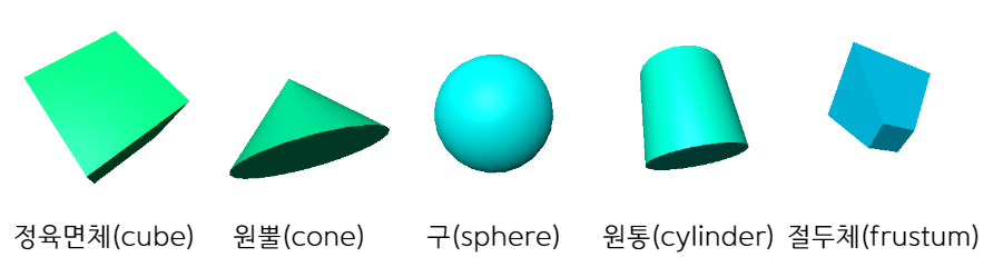
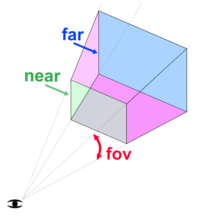
PerspectiveCamera 는 절두체(frustum)를 만든다. 절두체는 입체를 절단하는 하나 또는 두 평행면 사이의 부분을 의미한다.
여기서 입체란 정육면체, 원뿔, 구 등의 3D 요소다.
PerspectiveCamera 는 4가지 속성을 바탕으로 절두체를 만든다.
near: 절두체가 어디서 시작할지 결정far: 절두체의 끝fov: 시야각으로,near와 카메라의 거리에 따른 절두체 높이를 계산하여 적용aspect: 절두체의 너비에 관여하는 비율. 절두체의 너비는 절두체 높이에 이 비율을 곱한 값
이 전의 바닥면, 구체, 정육면체로 이룬 예제를 다시 사용해보자.
near 속성은 항상 far 속성보다 커야하니 이를 제어할 MinMaxGUIHelper 헬퍼 클래스를 만든다.
이 클래스는 dat.GUI가 제어할 min 과 max 속성이 있고, dat.GUI가 이를 조정할 때 지정한 두 가지 속성을 동시에 변경한다.
const MinMaxGUIHelper {
  constructor(obj, minProp, maxProp, minDif) {
    this.obj = obj;
    this.minProp = minProp;
    this.maxProp = maxProp;
    this.minDif = minDif;
  }
  get min() {
    return this.obj[this.minProp];
  }
  set min(v) {
    this.obj[this.minProp] = v;
    this.obj[this.maxProp] = Math.max(this.obj[this.maxProp], v + this.minDif);
  }
  get max() {
    return this.obj[this.maxProp];
  }
  set max(v) {
    this.obj[this.maxProp] = v;
    this.min = this.min;
  }
}
이제 GUI를 만들어보자.
function updateCamera() {
  camera.updateProjectionMatrix();
}

const gui = new GUI();
gui.add(camera, 'fov', 1, 180).onChange(updateCamera);
const minMaxGUIHelper = new MinMaxGUIHelper(camera, 'near', 'far', 0.1);
gui.add(minMaxGUIHelper, 'min', 0.1, 50, 0.1).name('near').onChange(updateCamera);
gui.add(minMaxGUIHelper, 'max', 0.1, 50, 0.1).name('far').onChange(updateCamera);
카메라 속성을 변경할 때마다 카메라의 updateProjectMatrix 메소드를 호출해야 하므로, updateCamera 라는 함수를 만들어 값이 변경될 때마다 함수를 호출하도록 한다.
아직 카메라가 어떻게 작동하는지 보기 어려우니 카메라를 하나 더 만든다.
하나는 위 예제 방식이며, 다른 하나는 시야와 절두체를 렌더링하여 움직임을 관찰할 수 있도록 하는 것이다.
Three.js 의 가위 함수를 이용하면쉽다. 가위 함수로 양쪽에 장면 두 개, 카메라 두 개를 렌더링한다.
먼저 HTML과 CSS 로 양쪽에 div 요소를 배치한다.
이러면 각각의 카메라에 OrbitControls 를 두어 이벤트 처리도 간단히 한다.
<body>
  <canvas id="c"></canvas>
  <div class="split">
     <div id="view1" tabindex="1"></div>
     <div id="view2" tabindex="2"></div>
  </div>
</body>
CSS로 두 div 요소가 canvas 위 양쪽에 자리하게 한다.
.split {
  position: absolute;
  left: 0;
  top: 0;
  width: 100%;
  height: 100%;
  display: flex;
}
.split > div {
  width: 100%;
  height: 100%;
}
카메라의 절두체를 시각화할 CameraHelper 를 추가한다.
const cameraHelper = new THREE.CameraHelper(camera);

...

scene.add(cameraHelper);
다음으로 두 div 요소를 참조한다.
const view1Elem = document.querySelector('#view1');
const view2Elem = document.querySelector('#view2');
그리고 기존 OrbitControls 가 왼쪽 div 요소의 이벤트만 반등하게 한다.
// const controls = new OrbitControls(camera, canvas);
const controls = new OrbitControls(camera, view1Elem);
다음으로 PerspectiveCamera 와 두 번째 OrbitControls 를 추가한다.
이 OrbitControls 를 두 번째 카메라에 종속시키고, 왼쪽 div 요소의 이벤트에만 반응하게 한다.
const camera2 = new THREE.PerspectiveCamera(
  60,
  2,
  0.1,
  500
);
camera2.position.set(40, 10, 30);
camera2.lookAt(0, 5, 0);

const controls2 = new OrbitControls(camera2, view2Elem);
constrols2.target.set(0, 5, 0);
controls2.update();
끝으로 가위 함수로 화면을 분할한다.
카메라 각각의 시점에 따라 장면을 캔버스 양쪽에 나누어 렌더링하게 한다.
아래 함수는 캔버스 위에 덮어 씌운 요소의 좌표(rectangle)를 구한다.
그리고 해당 사각 좌표로 renderer 의 화면(viewport)과 가위(scissor)의 값을 정의한 뒤, 사각 좌표의 가로세로 비율을 반환한다.
function setScissorForElement(elem) {
  const canvasRect = canvas.getBoundingClientRect();
  const eleRect = elem.getBoundingClientRect();

  // 캔버스에 대응하는 사각형 구하기
  const right = Math.min(elemRect.right, canvasRect.right) - canvasRect.left;
  const left = Math.max(0, elemRect.left - canvasRect.left);
  const bottom = Math.min(elemRect.bottom, canvasRect.bottom) - canvasRect.top;
  const top = Math.max(0, elemRect.top - canvasRect.top);

  const width = Math.min(canvasRect.width, right - left);
  const height = Math.min(canvasRect.height, bottom - top);

  // canvas의 일부분만 렌더링하도록 scissor 적용
  const positiveYUpBottom = canvasRect.height - bottom;
  renderer.setScissor(left, positiveYUpBottom, width, height);
  renderer.setViewport(left, positiveYUpBottom, width, height);

  // 비율 반환
  return width / height;
}
이제 이 함수로 render 함수에서 장면을 두 번 렌더링할 수 있다.
  ...

  function render() {
    /*
    if (resizeRendererToDisplaySize(renderer)) {
      const canvas = renderer.domElement;
      camera.aspect = canvas.clientWidth / canvas.clientHeight;
      camera.updateProjectionMatrix();
    }
    */

    resizeRendererToDisplaySize(renderer);

    // 가위 활성화
    renderer.setScissorTest(true);

    // 기존 화면 렌더링
    {
      const aspect = setScissorForElement(view1Elem);

      // 비율에 따라 카메라 조정
      camera.aspect = aspect;
      camera.updateProjectionMatrix();
      cameraHelper.update();

      // 기존 화면에서 가이드라인(CameraHelper)이 노출되지 않도록 설정
      cameraHelper.visible = false;

      scene.background.set(0x000000);

      // 렌더링
      renderer.render(scene, camera);
    }

    // 두 번째 카메라 렌더링
    {
      const aspect = setScissorForElement(view2Elem);

      // 비율에 따라 카메라 조정
      camera2.aspect = aspect;
      camera2.updateProjectionMatrix();

      // 가이드라인 활성화
      cameraHelper.visible = true;

      scene.background.set(0x000040);

      renderer.render(scene, camera2);
    }

    // renderer.render(scene, camera);

    requestAnimationFrame(render);
  }

  requestAnimationFrame(render);
}
위 예제에선 분할딘 두 화면을 구별하기 쉽게 두 번째 화면의 배경을 진한 파란색으로 칠했다.
그리고 render 함수 안에서 모든 것을 처리하기에 updateCamera 함수도 제거했다.
/*
function updateCamera() {
  camera.updateProjectionMatrix();
}
*/

const gui = new GUI();
// gui.add(camera, 'fov', 1, 180).onChange(updateCamera);
gui.add(camera, 'fov', 1, 180);
const minMaxGUIHelper = new MinMaxGUIHelper(camera, 'near', 'far', 0.1);
// gui.add(minMaxGUIHelper, 'min', 0.1, 50, 0.1).name('near').onChange(updateCamera);
gui.add(minMaxGUIHelper, 'max', 0.1, 50, 0.1).name('far').onChange(updateCamera);
gui.add(minMaxGUIHelper, 'min', 0.1, 50, 0.1).name('near');
gui.add(minMaxGUIHelper, 'max', 0.1, 50, 0.1).name('far');
이제 두 번째 화면에서 첫 번째 카메라의 절두체를 확인할 수 있다.
혹시나 near 를 0.00000..1 로 설정하고 far 를 1000..0 로 설정하면 다 보인다고 생각할 수 있다. GPU 는 어떤 물체가 앞에 있거나 뒤에 있을 때만 정밀도가 높은데, 정밀도는 일정량이 near 와 far 사이에 퍼져 있는데, 기본적으로 카메라에 가꾸울 수록 정밀도가 높고 물 수록 낮다.
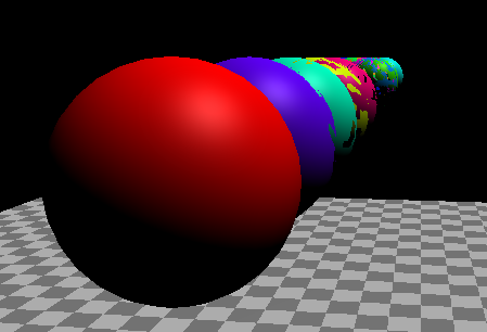
현상을 직접 살펴보자.
20체의 구를 한 줄로 세워본다.
{
  const sphereRadius = 3;
  const sphereWidthDivisions = 32;
  const sphereHeightDivisions = 16;
  const sphereGeo = new THREE.SphereGeometry(sphereRadius, sphereWidthDivisions, sphereHeightDivisions);
  const numSphere = 20;
  for (let i = 0; i < numSphere; ++i) {
    const sphereMat = new THREE.MeshPhongMaterial();
    sphereMat.color.setHSL(i * .73, i, 0.5);
    const mesh = new THREE.Mesh(sphereGeo, sphereMat);
    mesh.position.set(-sphereRadius - 1, sphereRadius + 2, i * sphereRadius * -2.2);
    scene.add(mesh);
  }
}
그리고 기존 코드를 수정해 0.00001 의 작은 단위로 설정하자.
// gui.add(minMaxGUIHelper, 'min', 0.1, 50, 0.1).name('near').onChange(updateCamera);
gui.add(minMaxGUIHelper, 'min', 0.00001, 50, 0.00001).name('near').onChange(updateCamera);
결과는 다음과 같다.
이는 z-파이팅(z-fighting, Stitching)의 한 예이다.
컴퓨터의 GPU가 어느 픽셀이 앞이고 뒤인지 결정할 정밀도가 모랄라 발생하는 현상이다.
한 가지 해결책은 Three.js 에게 앞 뒤 결정을 다른 방법으로 쓰게 설정하는 것이다.
WebGLRenderer 를 설정할 때 logarithmicDepthBuffer 속성을 활성화하면 된다.
// const renderer = new THREE.WebGLRenderer({canvas});
const renderer = new THREE.WebGLRenderer({
  canvas,
  logarithmicDepthBuffer: true,
});
이 해결책은 일부 GPU만 이 기능을 지원하는데, 거의 모든 데스크탑은 지원하나 모바일은 대부분이 지원하지 않으며, 훨씬 성능이 나쁘기 때문에 쓰지 말아야 한다.
게다가 이 기능은 near 를 더 작게, far 를 더 멀게 설정하면 결국 같은 현상을 만난다.
이는 항상 near 와 far 를 설정하는데 신경써야 한다는 의미다.
두 번째는 OrthographicCamera(정사영 카메라) 이다.
절두체 대신 left, right, top, bottom, near, far 로 육면체를 정의하는 것이다. 육면체로 화면을 투사하기에 원근 효과가 없다.
2분할 화면 예제로 첫 번째 화면을 OrthographicCamera 로 바꾸자.
const left = -1;
const right = 1;
const top = 1;
const bottom = -1;
const near = 5;
const far = 50;
const camera = new THREE.OrthographicCamera(left, right, top, bottom, near, far);
camera.zoom = 0.2;
먼저 left 와 bottom 을 -1, right 와 top 을 1로 설정하여 육면체는 너비 2칸 높이 2칸이다.
다음으로 zoom 속성을 조정할 수 있도록 추가한다.
const hgui = new GUI();
gui.add(camera, 'zoom', 0.01, 1, 0.01).listen();
listen 메소드를 호출하면 dat.GUI가 변화를 감지한다.
이런 이유는 OrbitControls 는 마우스 휠 스크롤을 감지하여 zoom 속성을 변경하기 때문이다.
마지막으로 왼쪽 화면을 렌더링할 때 OrthographicCamera 를 업데이트하도록 설정한다.
{
  const aspect = setScissorForElement(view1Elem);

  // 요소의 비율에 맞춰 카메라 업데이트
  // camera.aspect = aspect;
  camera.left   = -aspect;
  camera.right  =  aspect;
  camera.updateProjectionMatrix();
  cameraHelper.update();

  // 기존 화면에서 가이드라인(CameraHelper)이 노출되지 않도록 설정
  cameraHelper.visible = false;

  scene.background.set(0x000000);
  renderer.render(scene, camera);
}
OrthographicCamera 는 주로 2D 요소를 표현하기 위해 사용한다.
카메라에 많은 요소를 보여줄지만 결정하면 된다. 만약 캔버스의 1픽셀을 카메라의 한 칸과 같읕 크기로 지정하고 싶다면 중점을 장면 중심에 두고 1픽셀을 한 칸으로 만들 수 있다.
camera.left = -canvas.width / 2;
camera.right = canvas.width / 2;
camera.top = canvas.height / 2;
camera.bottom = -canvas.height / 2;
camera.near = -1;
camera.far = 1;
camera.zoom = 1;
2D 캔버스처럼 중점을 상단 위쪽에 두려면 다음처럼 설정할 수 있다.
camera.left = 0;
camera.right = canvas.width;
camera.top = 0;
camera.bottom = canvas.height;
camera.near = -1;
camera.far = 1;
camera.zoom = 1;
중점이 상단 왼쪽에 있다면 좌표는 2D 캔버스처럼 (0, 0)이다.
먼저 카메라를 설정해보자.
const left = 0;
const right = 300;  // canvas 기본 크기
const top = 0;
const bottom = 150;  // canvas 기본 크기
const near = -1;
const far = 1;
const camera = new THREE.OrthographicCamera(left, right, top, bottom, near, far);
camera.zoom = 1;
다음으로 평면 6개를 만들어 각각 다른 텍스처를 적용해보자.
각 평면마다 THREE.Object3D 인스턴스를 만들어 평면의 부모로 설정한다. 이럼 중점을 0, 0, 상단 좌측으로 지정해 좌표를 지정하기 쉽다.
const loader = new THREE.TextureLoader();
const textures = [
  loader.load('resources/images/flower-1.jpg'),
  loader.load('resources/images/flower-2.jpg'),
  loader.load('resources/images/flower-3.jpg'),
  loader.load('resources/images/flower-4.jpg'),
  loader.load('resources/images/flower-5.jpg'),
  loader.load('resources/images/flower-6.jpg'),
];
const planeSize = 256;
const planeGeo = new THREE.PlaneGeometry(planeSize, planeSize);
const planes = textures.map((texture) => {
  const planePivot = new THREE.Object3D();
  scene.add(planePivot);
  texture.magFlilter = THREE.NearestFilter;
  const planeMat = new THREE.MeshBasicMaterial({
    map: texture,
    side: THREE.DoubleSide,
  });
  const mesh = new THREE.Mesh(planeGeo, planeMat);
  planePivot.add(mesh);
  // 평면을 움직이며 상단 좌측이 중점이 되게 설정
  mesh.position.set(planeSize / 2, planeSize / 2, 0);
  return planePivot;
});
그리고 render 함수 안에 캔버스의 사이즈가 변경되었을 때 카메라를 업데이트하는 코드를 추가한다.
function render() {

  if (resizeRendererToDisplaySize(renderer)) {
    camera.right = canvas.width;
    camera.bottom = canvas.height;
    camera.updateProjectionMatrix();
  }

  ...
planes 는 평면의 배열로, 시간값을 기반으로 움직이게 한다.
function render(time) {
time *= 0.001; // 초 단위로 변경
...
const distAcross = Math.max(20, canvas.width - planeSize);
const distDown = Math.max(20, canvas.height - planeSize);
// total distance to move across and back
const xRange = distAcross * 2;
const yRange = distDown * 2;
const speed = 180;
planes.forEach((plane, ndx) => {
// compute a unique time for each plane
const t = time * speed + ndx * 300;
// get a value between 0 and range
const xt = t % xRange;
const yt = t % yRange;
// set our position going forward if 0 to half of range
// and backward if half of range to range
const x = xt < distAcross ? xt : xRange - xt;
const y = yt < distDown ? yt : yRange - yt;
plane.position.set(x, y, 0);
});
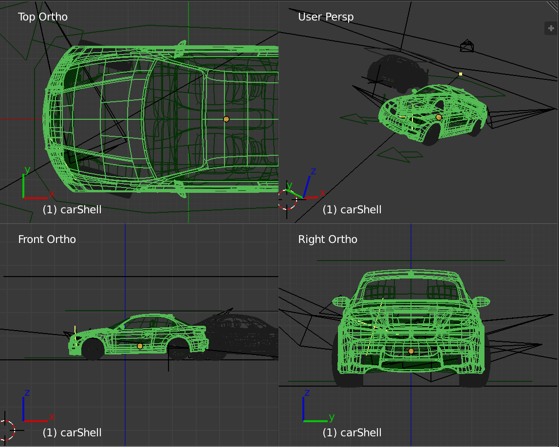
renderer.render(scene, camera);OrthographicCamera 는 게임 엔진 에디터 등에서 처럼 3D 모델링 결과물의 상, 하, 좌, 우, 앞, 뒤를 렌더링할 때도 사용한다.
Three.js 그림자
Three.js 는 기본적으로 그림자 맵을 사용한다.
그림자를 만드는 빛의 영향을 받는, 그림자를 드리우는 모든 물체를 빛의 시점에서 렌더링하는 기법이다.
조명 개수마다 그만큼 렌더링을 해야하므로 보통 조명이 여러 개라도 한 조명만 그림자를 지게끔 한다.
물론 라이트맵이나 앰비언트 오클루전을 이용해 빛의 영향을 미리 계산할 수도 있다. 이럼 정적 조명이나 정적 빛 반사를 사용하는 것이기에 수정이 어렵지만, 적어도 성능이 빠르다.
가짜 그림자도 한 방법이다. 평면을 만들어, 흑백 텍스처를 입혀 땅 위에 그림자가 있을 위치에 그린다.
예로 아래 텍스처를 사용해 가짜 그림자를 만들어보자.

먼저 흰색 배경을 만든다.
const scene = new THREE.Scene();
scene.background = new THREE.Color('white');
같은 체크판 무늬 땅을 사용하되, 땅이 조명의 영향을 받지 않으니 MeshBasicMaterial 을 사용한다.
const loader = new THREE.TextureLoader();

{
  const planeSize = 40;

  const texture = loader.load('resources/images/checker.png');
  texture.wrapS = THREE.RepeatWrapping;
  texture.wrapT = THREE.RepeatWrapping;
  texture.magFilter = THREE.NearestFilter;
  const repeats = planeSize / 2;
  texture.repeat.set(repeats, repeats);

  const planeGeo = new THREE.PlaneGeometry(planeSize, planeSize);
  const planeMat = new THREE.MeshBasicMaterial({
    map: texture,
    side: THREE.DoubleSide,
  });
  planeMat.color.setRGB(1.5, 1.5, 1.5);
  const mesh = new THREE.Mesh(planeGeo, planeMat);
  mesh.rotation.x = Math.PI * -.5;
  scene.add(mesh);
}
평면 색상을 (1.5, 1.5, 1.5)로 설정했다.
이제 그림자 텍스처를 로드하자.
const shadowTexture = loader.load('resources/images/roundshadow.png');구체와 관련된 객체를 분류하기 위해 배열을 만든다.
const sphereShadowBases = [];다음으로 구체 geometry 를 만든다.
const sphereRadius = 1;
const sphereWidthDivisions = 32;
const sphereHeightDivisions = 16;
const sphereGeo = new THREE.SphereGeometry(sphereRadius, sphereWidthDivisions, sphereHeightDivisions);
가짜 그림자를 위한 평면 geometry 도 만든다.
const planeSize = 1;
const shadowGeo = new THREE.PlaneGeometry(planeSize, planeSize);
이제 구체를 많이 만들어본다.
각 구체마다 컨테이너 역할을 할 THREE.Object3D 를 만들고, 그림자 평면 mesh, 구체 mesh 를 이 컨테이너의 자식으로 만든다.
이럼 구체와 그림자를 동시에 움직일 수 있다. z-파이팅 현상을 막기 위해 그림자는 땅보다 약간 위에 둔다. 또 depthWrite 속성을 false 로 설정해 그림자끼리 충돌하는 현상을 막는다.
구체의 색상을 각각 다르게 지정하고, 컨테이너, 구체 mesh, 그림자 mesh 와 구체의 처음 y축 좌표를 배열에 기록한다.
const numSpheres = 15;
for (let i = 0; i < numSpheres; ++i) {
  // 구체와 그림자가 같이 움직이도록 컨테이너(base)를 만듭니다
  const base = new THREE.Object3D();
  scene.add(base);

  /**
   * 그림자를 컨테이너에 추가합니다
   * 주의: 여기서는 각 구체의 투명도를 따로 설정할 수 있도록
   * 재질을 각각 따로 만듬
   */
  const shadowMat = new THREE.MeshBasicMaterial({
    map: shadowTexture,
    transparent: true,    // 땅이 보이도록
    depthWrite: false,    // 그림자를 따로 정렬하지 않도록
  });
  const shadowMesh = new THREE.Mesh(shadowGeo, shadowMat);
  shadowMesh.position.y = 0.001;  // 그림자를 땅에서 살짝 위에 배치
  shadowMesh.rotation.x = Math.PI * -.5;
  const shadowSize = sphereRadius * 4;
  shadowMesh.scale.set(shadowSize, shadowSize, shadowSize);
  base.add(shadowMesh);

  // 구체를 컨테이너에 추가
  const u = i / numSpheres;   // 반복문이 진행됨에 따라 0에서 1사이 값을 지정
  const sphereMat = new THREE.MeshPhongMaterial();
  sphereMat.color.setHSL(u, 1, .75);
  const sphereMesh = new THREE.Mesh(sphereGeo, sphereMat);
  sphereMesh.position.set(0, sphereRadius + 2, 0);
  base.add(sphereMesh);

  // y축 좌표를 포함해 나머지 요소를 기록
  sphereShadowBases.push({ base, sphereMesh, shadowMesh, y: sphereMesh.position.y });
}
조명은 2개를 만들겠다.
하나는 HemisphereLight, 강도를 2로 설정해 화면을 아주 밝게 설정한다.
{
  const skyColor = 0xB1E1FF;  // 하늘색
  const groundColor = 0xB97A20;  // 오렌지 브라운
  const intensity = 2;
  const light = new THREE.HemisphereLight(skyColor, groundColor, intensity);
  scene.add(light);
}
다른 하나는 구체의 윤곽을 좀 더 분명하게 해 줄 DirectionalLight 이다.
{
  const color = 0xFFFFFF;
  const intensity = 1;
  const light = new THREE.DirectionalLight(color, intensity);
  light.position.set(0, 10, 5);
  light.target.position.set(-5, 0, 0);
  scene.add(light);
  scene.add(light.target);
}
이대로도 좋지만 구체들에 애니메이션을 줘보자.
컨테이너를 움직여, 그림자가 xz축 평면을 따라 움직이게 하고, Math.abs(Math.sin(time)) 를 사용해 구체에 공처럼 통통 튀는 애니메이션을 넣어준다. 또 그림자 재질의 투명도를 조절하여 구체가 높을수록 그림자가 옅어 지도록 한다.
function render(time) {
  time *= 0.001;  // 초 단위로 변환

  ...

  sphereShadowBases.forEach((sphereShadowBase, ndx) => {
    const { base, sphereMesh, shadowMesh, y } = sphereShadowBase;

    // u는 구체의 반복문을 실행하면서 인덱스에 따라 0 이상, 1 이하로 지정됩니다
    const u = ndx / sphereShadowBases.length;

    /**
     * 컨테이너의 위치를 계산합니다. 구체와 그림자가
     * 컨테이너에 종속적이므로 위치가 같이 변합니다
     */
    const speed = time * .2;
    const angle = speed + u * Math.PI * 2 * (ndx % 1 ? 1 : -1);
    const radius = Math.sin(speed - ndx) * 10;
    base.position.set(Math.cos(angle) * radius, 0, Math.sin(angle) * radius);

    // yOff 값은 0 이상 1 이하입니다
    const yOff = Math.abs(Math.sin(time * 2 + ndx));
    // 구체를 위아래로 튕김
    sphereMesh.position.y = y + THREE.MathUtils.lerp(-2, 2, yOff);
    // 구체가 위로 올라갈수록 그림자가 옅어짐
    shadowMesh.material.opacity = THREE.MathUtils.lerp(1, .25, yOff);
  });

  ...
15가지 색상의 탱탱볼을 완성했다.
물론 다른 그림자를 사용해도 좋다.
그림자 경계를 분명하게 할 수도 있지만 모든 그림자를 둥글게 표현하는 경우가 좋은 부분도 있다. 예로는 동물의 숲이다.
자연그러우면서 성능 면에서도 이득이다.
이제 그림자를 드리울 조명 3가지, DirectionalLight, PointLight, SpotLight 이다.
먼저 DirectionalLight 부터 보자.
먼저 renderer 의 그림자 맵 옵션을 킨다.
const renderer = new THREE.WebGLRenderer({canvas});
renderer.shadowMap.enabled = true;
조명도 그림자를 드리우도록 옵션을 활성화한다.
const light = new THREE.DirectionalLight(color, intensity);
light.castShadow = true;
또한 장면 안 각 mesh 마다 그림자를 드리울지, 그림자의 영향을 받을지 설정해줘야 한다.
바닥 아래는 굳이 신경 쓸 필요가 없으니 평면은 그림자의 영향만 받게 한다.
const mesh = new THREE.Mesh(planeGeo, planeMat);
mesh.receiveShadow = true;
정육면체와 구체는 그림자도 드리우고, 영향도 받도록 설정한다.
const mesh = new THREE.Mesh(cubeGeo, cubeMat);
mesh.castShadow = true;
mesh.receiveShadow = true;

...

const mesh = new THREE.Mesh(sphereGeo, sphereMat);
mesh.castShadow = true;
mesh.receiveShadow = true;
실행해보자.
그림자 일부가 잘려진 것을 볼 수 있다.
이는 빛의 시점에서 장면을 렌더링하여 그림자 맵을 만들기 때문인데, DirectionalLight 의 위치에 카메라가 있고, 해당 조명의 목표를 바라보는 것이다.
조명의 그림자엔 별도의 카메라가 있고, 일정 공간 안의 그림자만 렌더링한다.
위 예제에서는 그 공간이 너무 좁은 것이다.
그림자용 카메라를 시각화하기 위해 조명의 그림자 속성에서 카메라를 가져와 CameraHelper 를 생성한 뒤, 장면을 추가한다.
const cameraHelper = new THREE.CameraHelper(light.shadow.camera);
scene.add(cameraHelper);
이제 그림자가 렌더링되는 공간을 확인할 수 있다.
target 의 x 값을 조정해보면 그림자용 카메라 범위 안에 있는 곳에만 그림자가 보이는 것을 확인할 수 있다.
이 공간의 크기는 카메라 속성으로 수정해 바꿀 수 있다.
GUI에 추가해보자. DirectionalLight 는 빛이 평행으로 나아가므로, DirectionalLight 는 그림자용 카메라로 OrthographicCamera(정사영 카메라) 를 사용한다. 이 시야는 육면체나 절두체로 정의한다고 했다. left, right, top, bottom, near, far, zoom 속성을 지정한다.
헬퍼 클래스를 하나 더 만들자.
이 DimensionGUIHelper 는 객체와 속성 이름 2개를 인자로 받아, 하나의 값은 양수, 다른 값은 음수로 조정할 수 있게 한다.
class DimensionGUIHelper {
  constructor(obj, minProp, maxProp) {
    this.obj = obj;
    this.minProp = minProp;
    this.maxProp = maxProp;
  }
  get value() {
    return this.obj[this.maxProp] * 2;
  }
  set value(v) {
    this.obj[this.maxProp] = v /  2;
    this.obj[this.minProp] = v / -2;
  }
}
MinMaxGUIHelper 를 가져와 near 와 far 속성을 조작하는데 사용한다.
const gui = new GUI();
gui.addColor(new ColorGUIHelper(light, 'color'), 'value').name('color');
gui.add(light, 'intensity', 0, 2, 0.01);
{
  const folder = gui.addFolder('Shadow Camera');
  folder.open();
  folder.add(new DimensionGUIHelper(light.shadow.camera, 'left', 'right'), 'value', 1, 100)
    .name('width')
    .onChange(updateCamera);
  folder.add(new DimensionGUIHelper(light.shadow.camera, 'bottom', 'top'), 'value', 1, 100)
    .name('height')
    .onChange(updateCamera);
  const minMaxGUIHelper = new MinMaxGUIHelper(light.shadow.camera, 'near', 'far', 0.1);
  folder.add(minMaxGUIHelper, 'min', 0.1, 50, 0.1).name('near').onChange(updateCamera);
  folder.add(minMaxGUIHelper, 'max', 0.1, 50, 0.1).name('far').onChange(updateCamera);
  folder.add(light.shadow.camera, 'zoom', 0.01, 1.5, 0.01).onChange(updateCamera);
}
그리고 값을 바뀔 때마다 updateCamera 함수를 호출하도록 한다.
이 함수에서 조명, 헬퍼, 그림자용 카메라, 카메라 헬퍼를 업데이트한다.
function updateCamera() {
  // 헬퍼가 가이드라인을 그릴 때 필요한 조명 목표(target)의 matrixWorld를 업데이트 합니다
  light.target.updateMatrixWorld();
  helper.update();
  // 그림자용 카메라의 투영 행렬(projection matrix)를 업데이트합니다
  light.shadow.camera.updateProjectionMatrix();
  // 그림자용 카메라를 보기 위해 설치한 카메라의 헬퍼를 업데이트합니다
  cameraHelper.update();
}
updateCamera();
with 와 height 를 완전 큰 값을 설정하면 아래와 같은 현상이 난다.
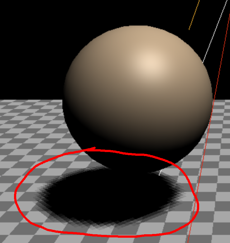
그림자 해상도가 낮아진다.
사실 그림자 맵은 그림자가 포함된 하나의 텍스처인데, 이는 크기가 정해져 있다. 카메라 공간이 늘면 텍스처도 는다.
그림자 맵 해상도는 light.shadow.mapSize 속성의 width, height 속성으로 설정한다. 이 크기는 클수록 메모리를 많이 차지하며 연산이 복잡하니 작게 설정하는 것이 좋다.
이는 공간도 마찬가지며, 작을 수록 그림자 퀄리티가 좋아지니 가능한 공간을 작게하자. 렌더링 용량도 정해져있으니 주의해야한다.
이 용량은 renderer.capabilities.maxTextureSize 로 확인한다.
SpotLight 는 그림자용 카메라로 PerspectiveCamera 를 사용한다.
DirectionalLight 의 그림자용 카메라는 거의 모든 속성을 직접 변경할 수 있었지만, SpotLight 의 그림자용 카메라는 조명 속성의 영향을 받는다. 카메라의 fov 속성은 SpotLight 의 angle 속성과 직접 연결되어 있다. aspect 는 그림자 맵의 크기에 따라 자동으로 정해진다.
// const light = new THREE.DirectionalLight(color, intensity);
const light = new THREE.SpotLight(color, intensity);
마지막으로 PointLight 는 모든 방향으로 빛을 발산하기에 관련 설정은 near 와 far 정도이다. 이는 각 면에 SpotLight 를 놓는 것과 같기 때문에 6번 렌더링하는 것과 같아서 렌더링 속도가 느리다.
이번엔 장면 주위에 상자를 두어 벽과 천장에도 그림자가 생길 수 있게 해보자. 먼저 재질의 side 속성을 THREE.BackSide 로 설정해 외부 상자의 밖이 아닌 안을 렌더링한다.
{
  const cubeSize = 30;
  const cubeGeo = new THREE.BoxGeometry(cubeSize, cubeSize, cubeSize);
  const cubeMat = new THREE.MeshPhongMaterial({
    color: '#CCC',
    side: THREE.BackSide,
  });
  const mesh = new THREE.Mesh(cubeGeo, cubeMat);
  mesh.receiveShadow = true;
  mesh.position.set(0, cubeSize / 2 - 0.1, 0);
  scene.add(mesh);
}
조명도 바꾼다.
// const light = new THREE.SpotLight(color, intensity);
const light = new THREE.PointLight(color, intensity);

....

// 조명이 위치를 확인하기 쉽도록 헬퍼 추가
const helper = new THREE.PointLightHelper(light);
scene.add(helper);
position 속성을 조정해 조명을 움직이면 벽에 그림자가 지는 걸 확인할 수 있다.
Three.js 안개
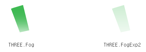
3D 엔진에서 안개는 카메라로부터 거리에 따른 특정 색상으로 점차 변화하는 것이다.
Three.js 에서는 Fog 나 FogExp2 객체를 생성하여, 장면의 fog 속성에 지정해 안개를 사용한다.
Fog 인자로 near 와 far 값을 받는데, 이는 카메라로부터의 거리값이다.
near 값보다 가까운 공간은 안개의 영향이 전혀 없고, far 값보다 먼 공간은 완전 안개에 뒤덮인다. near 와 far 사이 공간의 물체는 점차 안개의 색으로 변화한다.
FogExp2 는 카메라에서 멀어질수록 안개 강도가 강해진다.
두 가지 안개 모두 마찬가지로, 안개를 사용하려면 장면의 속성에 지정해야 한다.
const scene = new THREE.Scene();
{
  const color = 0xFFFFFF;
  const near = 10;
  const far = 100;
  scene.fog = new THREE.Fog(color, near, far);
}
FogExp2 의 경우는 다음과 같다.
const scene = new THREE.Scene();
{
  const color = 0xFFFFFF;
  const density = 0.1;
  scene.fog = new THREE.FogExp2(color, density);
}
FogExp2 가 더 현실적이긴 하나, 보통 안개의 범위를 특정하기 쉬운 Fog 를 더 많이 사용한다.
한 가지 알아야 하는 것은 안개는 렌더링되는 물체 라는 점이다. 물체의 픽셀을 렌더링할 때 같이 렌더링되는데, 안개 효과를 주려면 배경색과 같은 색으로 지정해야 한다.
배경색은 scene.background 속성을 THREE.Color 인스턴스로 지정해 바꿀 수 있다.
scene.background = new THREE.Color({'#F00'});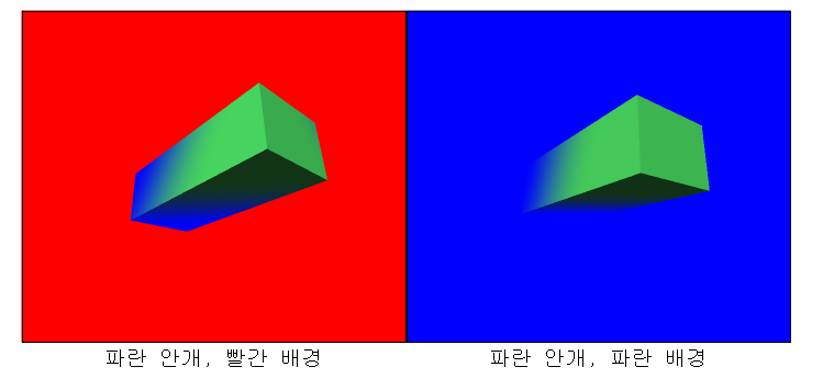
아래는 이전 예제에 안개를 추가한 것이다.
장면을 생성하고 안개를 추가한 후, 배경색만 바꿨다.
const scene = new THREE.Scene();

{
  const near = 1;
  const far = 2;
  const color = 'lightblue';
  scene.fog = new THREE.Fog(color, near, far);
  scene.background = new THREE.Color(color);
}
아래는 near 값이 0.1, far 값이 5이다.
카메라 위치는 z = 2 이다.
인터페이스에 안개를 조정할 수 있게 해보자.
안개 헬퍼 클래스를 만들어 near 값이 far 값보다 큰 경우는 없으니 헬퍼에 near 값을 항상 far 이하로 만들고 far 값을 항상 near 이상으로 설정한다.
/**
 * 이 클래스의 인스턴스를 dat.GUI에 넘겨
 * near나 far 속성을 조정할 때 항상
 * near는 never >= far, far는 never <= near가 되도록 합니다
 **/
class FogGUIHelper {
  constructor(fog) {
    this.fog = fog;
  }
  get near() {
    return this.fog.near;
  }
  set near(v) {
    this.fog.near = v;
    this.fog.far = Math.max(this.fog.far, v);
  }
  get far() {
    return this.fog.far;
  }
  set far(v) {
    this.fog.far = v;
    this.fog.near = Math.min(this.fog.near, v);
  }
}
이 클래스를 활용해보자.
{
  const near = 1;
  const far = 2;
  const color = 'lightblue';
  scene.fog = new THREE.Fog(color, near, far);
  scene.background = new THREE.Color(color);

  const fogGUIHelper = new FogGUIHelper(scene.fog);
  gui.add(fogGUIHelper, 'near', near, far).listen();
  gui.add(fogGUIHelper, 'far', near, far).listen();
}
언개의 색까지 조정해보자. dat.GUI의 색상 타입은 4가지로, 하나는 CSS hex string 이고, 하나는 hue, saturation, value 객체, 하나는 RGB 배열 마지막으로 RGBA 색상 배열이다.
간단한 16진수 문자열을 사용해보자. THREE.Color 의 getHexString 메소드로 전달해본다.
/**
 * 이 클래스의 인스턴스를 dat.GUI에 넘겨
 * near나 far 속성을 조정할 때 항상
 * near는 never >= far, far는 never <= near가 되도록 합니다
 **/
// 또 dat.GUI가 color 속성을 조작할 때 안개와 배경색을 동시에 변경합니다
class FogGUIHelper {
  constructor(fog, backgroundColor) {
    this.fog = fog;
    this.backgroundColor = backgroundColor;
  }
  get near() {
    return this.fog.near;
  }
  set near(v) {
    this.fog.near = v;
    this.fog.far = Math.max(this.fog.far, v);
  }
  get far() {
    return this.fog.far;
  }
  set far(v) {
    this.fog.far = v;
    this.fog.near = Math.min(this.fog.near, v);
  }
  get color() {
    return `#${this.fog.color.getHexString()}`;
  }
  set color(hexString) {
    this.fog.color.set(hexString);
    this.backgroundColor.set(hexString);
  }
}
이번엔 gui.addColor 메소드를 호출하여 색상 UI를 생성하여 조작할 수 있게 설정한다.
{
  const near = 1;
  const far = 2;
  const color = 'lightblue';
  scene.fog = new THREE.Fog(color, near, far);
  scene.background = new THREE.Color(color);

  const fogGUIHelper = new FogGUIHelper(scene.fog, scene.background);
  gui.add(fogGUIHelper, 'near', near, far).listen();
  gui.add(fogGUIHelper, 'far', near, far).listen();
  gui.addColor(fogGUIHelper, 'color');
}
near 값이 1.9, far 은 2.0 정도면 안개 경계가 선명할 것이다.
정육면체들이 카메라에서 2칸 떨어져있으니 near 를 1.1, far 을 2.9 정도로 하면 경계가 가장 부드러운 것이라 할 수 있다.
추가로 재질에는 불린 타입의 fog 속성이 있다.
해당 재질로 렌더링되는 물체가 안개의 영향을 받을지 여부를 결정하는 속성이다.
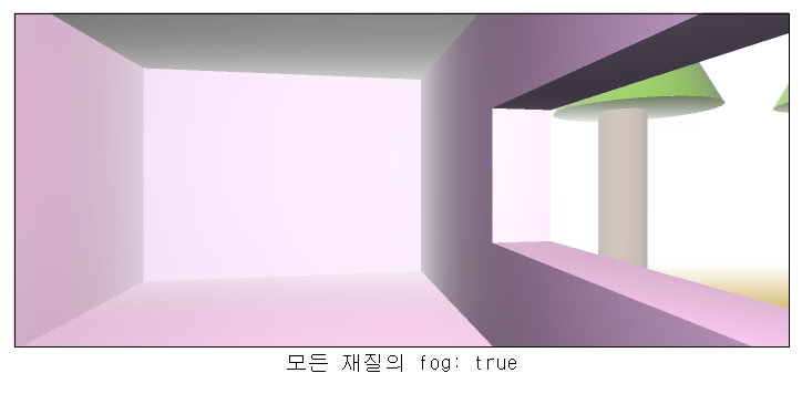
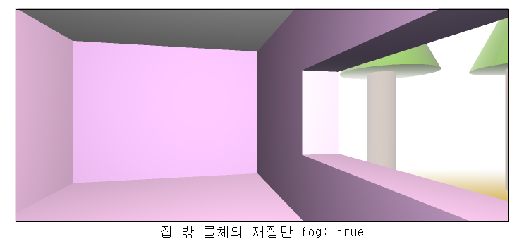
위와 같이, 방이 2미터, 집이 최소 4미터라 가정하면 잡 안의 재질은 안개가 끼면 안되니 위 예제처럼 집 밖의 재질만 안개가 끼도록 하여 창 밖만 안개가 낀 것처럼 보이게 한다.
Three.js 렌더 타켓
렌더 타겟은, 직접 렌더링할 수 있는 텍스처를 말한다.
한 번 텍스처로 렌더링한 뒤엔 다른 텍스처처럼 사용할 수 있다.
렌더 타겟을 만드는 방법은 기존 렌더링 방식과 비슷하다.
먼저 WebGLRenderTarget 인스턴스를 생성한다.
const rtWidth = 512;
const rtHeight = 512;
const enderTarget = new THREE.WebGLRenderTarget(rtWidth, rtHeight);
그리고 Camera 와 Scene 을 추가한다.
const rtFov = 75;
const rtAspect = rtWidth / rtHeight;
const rtNear = 0.1;
const rtFar = 5;
const rtCamera = new THREE.PerspectiveCamera(rtFov, rtAspect, rtNear, rtFar);
rtCamera.position.z = 2;

const rtScene = new THREE.Scene();
rtScene.background = new THREE.Color('red');
위 렌더 타겟을 정육면체의 텍스처로 사용하며, 정육면체의 모든 면은 정사각형이니 가로세로비는 1.0 이다.
조명과 정육면체 3개를 추가하자.
{
  const color = 0xFFFFFF;
  const intensity = 1;
  const light = new THREE.DirectionalLight(color, intensity);
  light.position.set(-1, 2, 4);
  rtScene.add(light);
}

const boxwidth = 1;
const boxHeight = 1;
const boxDepth = 1;
const geometry = new THREE.BoxGeometry(boxWidth, boxHeight, boxDepth);

function makeInstance(geometry, color, x) {
  const material = new THREE.MeshPhongMaterial({color});

  const cube = new THREE.Mesh(geometry, material);
  rtScene.add(cube);

  cube.position.x = x;

  return cube;
}

const rtCubes = [
  makeInstance(geometry, 0x44aa88, 0);
  makeInstance(geometry, 0x8844aa, -2);
  makeInstance(geometry, 0xaa8844, 2);
];
먼저 렌더 타겟의 텍스처를 사용하는 정육면체를 추가한다.
const material = new THREE.MeshPhongMaterial({
  map: renderTarget.texture,
});
const cube = new THREE.Mesh(geometry, material);
scene.add(cube);
그리고 render 함수 안에 렌더 타겟의 장면을 먼저 렌더링 한 뒤,
function render(time) {
  time *= 0.001;

  ...

  // 렌더 타겟의 장면 안에서 정육면체를 각각 회전시킨다.
  rtCubes.forEach((cube, ndx) => {
    const speed = 1 + ndx = .1;
    const rot = time * speed;
    cube.rotation.x = rot;
    cube.rotation.y = rot;
  });

  // 렌더 타겟의 장면을 렌더 타겟에 렌더링한다.
  renderer.setRenderTarget(renderTarget);
  render.render(rtScene, rtCamera);
  render.setRenderTarget(null);
캔버스에 렌더 타겟의 텍스처를 사용하는 정육면체를 렌더링한다.
// 장면 중앙의 정육면체를 회전시킨다.
cube.rotation.x = time;
cube.rotation.y = time * 1.1;

// 장면은 캔버스에 렌더링
render.render(scene, camera);
렌더 타겟의 용도는 무궁무진하며 그림자가 렌더 타겟을 사용하고, 피킹도 사용할 수 있다. 많은 후처리 효과를 사용할 때 필수일 수 있고, 차의 후사경(백미러)이나 모니터 화면 등에도 활용할 수 있다.
마지막으로 주의할 점을 살펴보자.
WebGLRenderTarget은 기본적으로 2개 텍스처를 생성한다.
하나는 색상 텍스처며, 다른 하나는 깊이/스텐실 텍스처다.
const rt = new THREE.WebGLRenderTarget(width, height, {
  depthBuffer: false,
  stencilBuffer: false,
});- 렌더 타겟 크기를 바꿔야 한다면 캔버스 사이즈를 변경하며, 카메라와 렌더 타겟의 사이즈를 같이 변경한다.
사용자 지정 BufferGeometry
BufferGeometry 는 Three.js 내의 모든 geometry 를 나타낸다.
한마디로 BufferAttribute 라는 속성의 집합이다.
각 BufferAttribute 는 위치, 법선, 색, uv 데이터의 배열이고, 이들을 모드면 각 꼭지점에 대한 평행 배열 형식의 데이터가 된다.
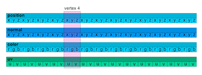
이들은 평행 배열로 각 속성의 N 번째 데이터 묶음이 한 꼭지점의 데이터를 나타낸다.
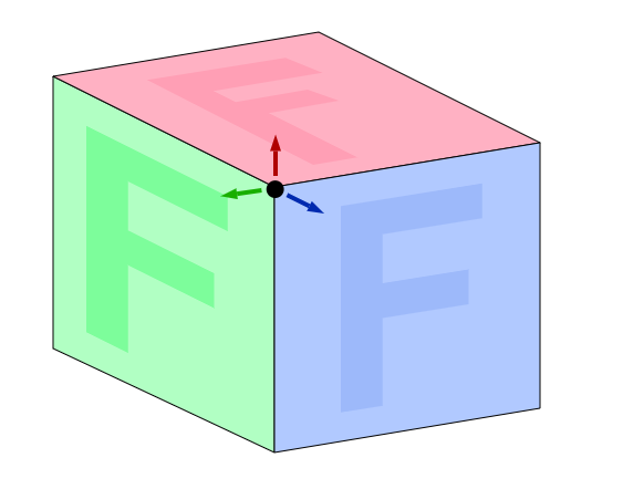
맞닿는 면의 색이 다르니, 모서리는 각 면에 다른 법선을 제공해야 한다.
마찬가지로 UV도 달라야 한다. 한 곡지점은 위 4개의 속성의 묶음이고, 때문에 속성이 달라지만 그건 다른 꼭지점이 된다는 것이다.
먼저 정육면체를 만드는데 필요한 데이터를 정렬한다.
정육면체의 꼭지점은 면 6개, 면 하나당 삼각형 2개, 삼각형 하나 당 꼭지점 3개이니 총 36개이다.
const vertices = [
  // 앞쪽
  { pos: [-1, -1,  1], norm: [ 0,  0,  1], uv: [0, 0], },
  { pos: [ 1, -1,  1], norm: [ 0,  0,  1], uv: [1, 0], },
  { pos: [-1,  1,  1], norm: [ 0,  0,  1], uv: [0, 1], },

  { pos: [-1,  1,  1], norm: [ 0,  0,  1], uv: [0, 1], },
  { pos: [ 1, -1,  1], norm: [ 0,  0,  1], uv: [1, 0], },
  { pos: [ 1,  1,  1], norm: [ 0,  0,  1], uv: [1, 1], },
  // 오른쪽
  { pos: [ 1, -1,  1], norm: [ 1,  0,  0], uv: [0, 0], },
  { pos: [ 1, -1, -1], norm: [ 1,  0,  0], uv: [1, 0], },
  { pos: [ 1,  1,  1], norm: [ 1,  0,  0], uv: [0, 1], },

  { pos: [ 1,  1,  1], norm: [ 1,  0,  0], uv: [0, 1], },
  { pos: [ 1, -1, -1], norm: [ 1,  0,  0], uv: [1, 0], },
  { pos: [ 1,  1, -1], norm: [ 1,  0,  0], uv: [1, 1], },
  // 뒤쪽
  { pos: [ 1, -1, -1], norm: [ 0,  0, -1], uv: [0, 0], },
  { pos: [-1, -1, -1], norm: [ 0,  0, -1], uv: [1, 0], },
  { pos: [ 1,  1, -1], norm: [ 0,  0, -1], uv: [0, 1], },

  { pos: [ 1,  1, -1], norm: [ 0,  0, -1], uv: [0, 1], },
  { pos: [-1, -1, -1], norm: [ 0,  0, -1], uv: [1, 0], },
  { pos: [-1,  1, -1], norm: [ 0,  0, -1], uv: [1, 1], },
  // 왼쪽
  { pos: [-1, -1, -1], norm: [-1,  0,  0], uv: [0, 0], },
  { pos: [-1, -1,  1], norm: [-1,  0,  0], uv: [1, 0], },
  { pos: [-1,  1, -1], norm: [-1,  0,  0], uv: [0, 1], },

  { pos: [-1,  1, -1], norm: [-1,  0,  0], uv: [0, 1], },
  { pos: [-1, -1,  1], norm: [-1,  0,  0], uv: [1, 0], },
  { pos: [-1,  1,  1], norm: [-1,  0,  0], uv: [1, 1], },
  // 상단
  { pos: [ 1,  1, -1], norm: [ 0,  1,  0], uv: [0, 0], },
  { pos: [-1,  1, -1], norm: [ 0,  1,  0], uv: [1, 0], },
  { pos: [ 1,  1,  1], norm: [ 0,  1,  0], uv: [0, 1], },

  { pos: [ 1,  1,  1], norm: [ 0,  1,  0], uv: [0, 1], },
  { pos: [-1,  1, -1], norm: [ 0,  1,  0], uv: [1, 0], },
  { pos: [-1,  1,  1], norm: [ 0,  1,  0], uv: [1, 1], },
  // 하단
  { pos: [ 1, -1,  1], norm: [ 0, -1,  0], uv: [0, 0], },
  { pos: [-1, -1,  1], norm: [ 0, -1,  0], uv: [1, 0], },
  { pos: [ 1, -1, -1], norm: [ 0, -1,  0], uv: [0, 1], },

  { pos: [ 1, -1, -1], norm: [ 0, -1,  0], uv: [0, 1], },
  { pos: [-1, -1,  1], norm: [ 0, -1,  0], uv: [1, 0], },
  { pos: [-1, -1, -1], norm: [ 0, -1,  0], uv: [1, 1], },
];
다음으로 이 배열을 3개의 평행 배열로 변환한다.
const positions = [];
const normals = [];
const uvs = [];
for (const vertex of vertices) {
  positions.push(...vertex.pos);
  normals.push(...vertex.norm);
  uvs.push(...vertex.uv);
}
이제 BufferGeometry 를 만들고 각 배열로 BufferAttribute 인스턴스를 생성하여 BufferGeometry 에 추가한다.
const geometry = new THREE.BufferGeometry();
const positionNumComponents = 3;
const normalNumComponents = 3;
const uvNumComponents = 2;
geometry.setAttribute(
  'position',
  new THREE.BufferAttribute(new Float32Array(positions), positionNumComponents));
geometry.setAttribute(
  'normal',
  new THREE.BufferAttribute(new Float32Array(normals), normalNumComponents));
geometry.setAttribute(
  'uv',
  new THREE.BufferAttribute(new Float32Array(uvs), uvNumComponents));
이때 정확히 Three.js 의 속성을 지정해야 한다.
이 경우 position, mormal, uv 이다. 꼭지점 색을 지정하려면 color 속성을 지정해야 한다.
데이터가 많으니 꼭지점을 인덱스로 참조하게끔 바꿔보자.
꼭지점 2개는 완전 같은 경우가 있으니 중복된 지점을 제거하고 불러오도록 하자.
const vertices = [
  // 앞쪽
  { pos: [-1, -1,  1], norm: [ 0,  0,  1], uv: [0, 0], }, // 0
  { pos: [ 1, -1,  1], norm: [ 0,  0,  1], uv: [1, 0], }, // 1
  { pos: [-1,  1,  1], norm: [ 0,  0,  1], uv: [0, 1], }, // 2

  // { pos: [-1,  1,  1], norm: [ 0,  0,  1], uv: [0, 1], },
  // { pos: [ 1, -1,  1], norm: [ 0,  0,  1], uv: [1, 0], },
  { pos: [ 1,  1,  1], norm: [ 0,  0,  1], uv: [1, 1], }, // 3
  // 오른쪽
  { pos: [ 1, -1,  1], norm: [ 1,  0,  0], uv: [0, 0], }, // 4
  { pos: [ 1, -1, -1], norm: [ 1,  0,  0], uv: [1, 0], }, // 5

  // { pos: [ 1,  1,  1], norm: [ 1,  0,  0], uv: [0, 1], },
  // { pos: [ 1, -1, -1], norm: [ 1,  0,  0], uv: [1, 0], },
  { pos: [ 1,  1,  1], norm: [ 1,  0,  0], uv: [0, 1], }, // 6
  { pos: [ 1,  1, -1], norm: [ 1,  0,  0], uv: [1, 1], }, // 7
  // 뒤쪽
  { pos: [ 1, -1, -1], norm: [ 0,  0, -1], uv: [0, 0], }, // 8
  { pos: [-1, -1, -1], norm: [ 0,  0, -1], uv: [1, 0], }, // 9

  // { pos: [ 1,  1, -1], norm: [ 0,  0, -1], uv: [0, 1], },
  // { pos: [-1, -1, -1], norm: [ 0,  0, -1], uv: [1, 0], },
  { pos: [ 1,  1, -1], norm: [ 0,  0, -1], uv: [0, 1], }, // 10
  { pos: [-1,  1, -1], norm: [ 0,  0, -1], uv: [1, 1], }, // 11
  // 왼쪽
  { pos: [-1, -1, -1], norm: [-1,  0,  0], uv: [0, 0], }, // 12
  { pos: [-1, -1,  1], norm: [-1,  0,  0], uv: [1, 0], }, // 13

  { pos: [-1,  1, -1], norm: [-1,  0,  0], uv: [0, 1], },
  { pos: [-1, -1,  1], norm: [-1,  0,  0], uv: [1, 0], },
  { pos: [-1,  1, -1], norm: [-1,  0,  0], uv: [0, 1], }, // 14
  { pos: [-1,  1,  1], norm: [-1,  0,  0], uv: [1, 1], }, // 15
  // 상단
  { pos: [ 1,  1, -1], norm: [ 0,  1,  0], uv: [0, 0], }, // 16
  { pos: [-1,  1, -1], norm: [ 0,  1,  0], uv: [1, 0], }, // 17

  // { pos: [ 1,  1,  1], norm: [ 0,  1,  0], uv: [0, 1], },
  // { pos: [-1,  1, -1], norm: [ 0,  1,  0], uv: [1, 0], },
  { pos: [ 1,  1,  1], norm: [ 0,  1,  0], uv: [0, 1], }, // 18
  { pos: [-1,  1,  1], norm: [ 0,  1,  0], uv: [1, 1], }, // 19
  // 하단
  { pos: [ 1, -1,  1], norm: [ 0, -1,  0], uv: [0, 0], }, // 20
  { pos: [-1, -1,  1], norm: [ 0, -1,  0], uv: [1, 0], }, // 21

  // { pos: [ 1, -1, -1], norm: [ 0, -1,  0], uv: [0, 1], },
  // { pos: [-1, -1,  1], norm: [ 0, -1,  0], uv: [1, 0], },
  { pos: [ 1, -1, -1], norm: [ 0, -1,  0], uv: [0, 1], }, // 22
  { pos: [-1, -1, -1], norm: [ 0, -1,  0], uv: [1, 1], }, // 23
];
이제 꼭지점 24개만 남았다.
중복되는 꼭지점은 없다. BufferGeometry.setIndex 메소드에 각 꼭지점 데이터의 인덱스 값 36개-삼각형이 12개를 넘겨준다.
geometry.setAttribute(
    'position',
    new THREE.BufferAttribute(positions, positionNumComponents));
geometry.setAttribute(
    'normal',
    new THREE.BufferAttribute(normals, normalNumComponents));
geometry.setAttribute(
    'uv',
    new THREE.BufferAttribute(uvs, uvNumComponents));

geometry.setIndex([
   0,  1,  2,   2,  1,  3,  // 앞쪽
   4,  5,  6,   6,  5,  7,  // 오른쪽
   8,  9, 10,  10,  9, 11,  // 뒤쪽
  12, 13, 14,  14, 13, 15,  // 왼쪽
  16, 17, 18,  18, 17, 19,  // 상단
  20, 21, 22,  22, 21, 23,  // 하단
]);
BufferGeometry 에 법선을 지정하지 않았다면 computeVertexNormals 메소드를 호출하여 자동으로 법선을 지정할 수 있다. 다만 데이터가 조금이라도 다르면 꼭지점을 공유할 수 없으니 구체나 원통 물체는 이음새가 보일 수 있다.
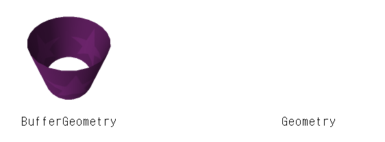
두 원통은 computeVertexNormals 메소드를 호출하여 법선을 생성했는데, 왼쪽 원통에 이음매가 있는것이 보일텐데 이는 원통의 끝과 시작점의 UV가 달라 꼭지점을 공유할 수 없기 때문이다. 큰 문제는 아니지만 해결하려면 법선을 직접 지정해야 한다.
아까는 순수 배열을 사용했지만, 형식화 배열을 사용할 수도 있다.
// const positions = [];
// const normals = [];
// const uvs = [];
const numVertices = vertices.length;
const positionNumComponents = 3;
const normalNumComponents = 3;
const uvNumComponents = 2;
const positions = new Float32Array(numVertices * positionNumComponents);
const normals = new Float32Array(numVertices * normalNumComponents);
const uvs = new Float32Array(numVertices * uvNumComponents);
let posNdx = 0;
let nrmNdx = 0;
let uvNdx = 0;
for (const vertex of vertices) {
  // positions.push(...vertex.pos);
  // normals.push(...vertex.norm);
  // uvs.push(...vertex.uv);
  positions.set(vertex.pos, posNdx);
  normals.set(vertex.norm, nrmNdx);
  uvs.set(vertex.uv, uvNdx);
  posNdx += positionNumComponents;
  nrmNdx += normalNumComponents;
  uvNdx += uvNumComponents;
}

geometry.setAttribute(
    'position',
    // new THREE.BufferAttribute(new Float32Array(positions), positionNumComponents));
    new THREE.BufferAttribute(positions, positionNumComponents));
geometry.setAttribute(
    'normal',
    // new THREE.BufferAttribute(new Float32Array(normals), normalNumComponents));
    new THREE.BufferAttribute(normals, normalNumComponents));
geometry.setAttribute(
    'uv',
    // new THREE.BufferAttribute(new Float32Array(uvs), uvNumComponents));
    new THREE.BufferAttribute(uvs, uvNumComponents));

geometry.setIndex([
   0,  1,  2,   2,  1,  3,  // 앞쪽
   4,  5,  6,   6,  5,  7,  // 오른쪽
   8,  9, 10,  10,  9, 11,  // 뒤쪽
  12, 13, 14,  14, 13, 15,  // 왼쪽
  16, 17, 18,  18, 17, 19,  // 상단
  20, 21, 22,  22, 21, 23,  // 하단
]);
꼭지점 일부를 수정하고 싶다면 형식화 배열이 더 좋다.
아래는 구체의 위치값과 인덱스를 생성하는 코드로, 사분면 내의 꼭지점은 서로 공유할 수 있지만, 사분면은 각각 움직여야 하므로 사분면끼리는 공유하지 않는다.
function makeSpherePositions(segmentsAround, segmentsDown) {
  const numVertices = segmentsAround * segmentsDown * 6;
  const numComponents = 3;
  const positions = new Float32Array(numVertices * numComponents);
  const indices = [];

  const longHelper = new THREE.Object3D();
  const latHelper = new THREE.Object3D();
  const pointHelper = new THREE.Object3D();
  longHelper.add(latHelper);
  latHelper.add(pointHelper);
  pointHelper.position.z = 1;
  const temp = new THREE.Vector3();

  function getPoint(lat, long) {
    latHelper.rotation.x = lat;
    longHelper.rotation.y = long;
    longHelper.updateMatrixWorld(true);
    return pointHelper.getWorldPosition(temp).toArray();
  }

  let posNdx = 0;
  let ndx = 0;
  for (let down = 0; down < segmentsDown; ++down) {
    const v0 = down / segmentsDown;
    const v1 = (down + 1) / segmentsDown;
    const lat0 = (v0 - 0.5) * Math.PI;
    const lat1 = (v1 - 0.5) * Math.PI;

    for (let across = 0; across < segmentsAround; ++across) {
      const u0 = across / segmentsAround;
      const u1 = (across + 1) / segmentsAround;
      const long0 = u0 * Math.PI * 2;
      const long1 = u1 * Math.PI * 2;

      positions.set(getPoint(lat0, long0), posNdx);  posNdx += numComponents;
      positions.set(getPoint(lat1, long0), posNdx);  posNdx += numComponents;
      positions.set(getPoint(lat0, long1), posNdx);  posNdx += numComponents;
      positions.set(getPoint(lat1, long1), posNdx);  posNdx += numComponents;

      indices.push(
        ndx, ndx + 1, ndx + 2,
        ndx + 2, ndx + 1, ndx + 3,
      );
      ndx += 4;
    }
  }
  return { positions, indices };
}
만든 함수를 다음과 같이 호출한다.
const segmentsAround = 24;
const segmentsDown = 16;
const { positions, indices } = makeSpherePositions(segmentsAround, segmentsDown);
반환된 위치값은 구체의 위치값으로 기반한다.
이는 법선의 값과 같으니 따로 구할 필요 없이 위치값을 복사하여 쓴다.
const normals = positions.slice();다음으로 각 속성을 지정한다.
const geometry = new THREE.BufferGeometry();
const positionNumComponents = 3;
const normalNumComponents = 3;

const positionAttribute = new THREE.BufferAttribute(positions, positionNumComponents);
positionAttribute.setUsage(THREE.DynamicDrawUsage);
geometry.setAttribute(
    'position',
    positionAttribute);
geometry.setAttribute(
    'normal',
    new THREE.BufferAttribute(normals, normalNumComponents));
geometry.setIndex(indices);
위치 속성에 참조값을 넘겨주고, 이 속성이 동적이라 명시했다.
이는 Three.js 에게 해당 속성이 자주 변경될 수 있음을 알려주는 역할을 한다.
이제 render 함수에 매 프레임마다 법선을 기준으로 위치값을 변경해준다.
const temp = new THREE.Vector3();

...

for (let i = 0; i < positions.length; i += 3) {
  const quad = (i / 12 | 0);
  const ringId = quad / segmentsAround | 0;
  const ringQuadId = quad % segmentsAround;
  const ringU = ringQuadId / segmentsAround;
  const angle = ringU * Math.PI * 2;
  temp.fromArray(normals, i);
  temp.multiplyScalar(THREE.MathUtils.lerp(1, 1.4, Math.sin(time + ringId + angle) * .5 + .5));
  temp.toArray(positions, i);
}
positionAttribute.needsUpdate = true;
마지막으로 positionAttribute.needsUpdate 속성을 활성화해 변화를 감지하도록 한다.
