1. 개요
이전 글에 이어 이번에는 영지식 증명 프로토콜에서의 circuit 최적화 방법에 대해 알아보자. 참고한 코드는 Scroll's poseidon hash circuit(scroll-dev-0723) 이며, 해당 깃허브 저장소에는 최적화된 버전의 poseidon hash circuit과 최적화 전의 circuit이 모두 포함되어 있다. 이번 글의 목표는 고도화된 circuit 최적화 방식을 실제 예제를 통해 이해하는 것이다.
2. 파라미터 및 기본 설정
Recap
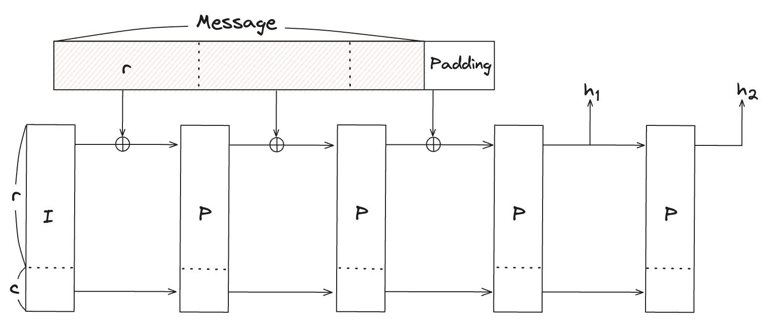
	r은 rate로 데이터 블록 길이에 해당하는 throughput, 데이터를 rate 단위로 나누어 연산
    c는 capacity로 안전성에 이 값이 클수록 더 높은 보안 수준을 의미, 처리 속도는 느려질 수 있음
    라운드 횟수: 스펀지 구조에서 permutation을 여러 라운드에 걸쳐 반복적으로 적용하는데, 이때 반복횟수
    state: permuation 과정에서 업데이트 되는 중간 계산 결과
    state의 길이는 t = r + c 으로 계산되며 라운드를 거치면서 값은 변경됨
Settings
다음에서 설정되는 파라미터 값들은 다양한 조합으로 설정 될 수 있다. 단, 값을 변경할 때에는 안전성을 고려해야 한다는 점에 유의해야한다.
-
로 정의되는 s-box 사용
-
RF = 8, RP = 57
-
capacity = 1
-
rate = 2
-
width() = 3 elements (rate + capacity)
	각 라운드 횟수: full 라운드 횟수(RF)는 총 8번, partial 라운드 횟수(RP)는 57번이며 full 라운드는 partial 라운드의 앞뒤로 배치한다.
  즉, full 라운드 4번 - partial 라운드 57번 - full라운드 4번의 순서로 구성한다.
Notation
다음의 표기에서 적고 있는 인덱스는 width 에 대해 범위에서 정의되며 인덱스는 범위에서 정의된다.
- : permutation 과정에서 각 라운드의 state의 값이 저장된 advice column
- : 번째 라운드에서 번째 state
- : permutation 과정에서 사용되는 round constant가 저장된 fixed column
- : round constant (*은 fixed column이 아니고 gate의 일부)
- : 최적화 방식 적용에 따라 새롭게 정의된 round constant
- : width 에 대해서 행렬로 정의되는 MDS 행렬과 그 역행렬
- : MDS 행렬의 번째 행벡터
- : MDS 역행렬의 번째 행벡터
- : 과 로 이루어진 binary vectors
- : permutation 과정에서 사용되는 selector column
3. Circuit 설계
Permutation 연산을 구성하는 gate
다음은 코드에서 정의하고 있는 gate들을 표로 나타내었다. 각 표에서 분홍색은 advice column, 하늘색은 fixed column에 해당하는 값을 구분하기 위하여 사용하였다. 초기 state는 로 정의되며, 초기 state에 더할 라운드 상수는 이다.
-
full round
permutation의 첫번째 라운드는 full 라운드로 시작한다. 아래 표는 selector 가 인 행에서, 상대적 위치로 정의되는 영역을 나타낸다.라운드의 state 에 적용할 연산의 표현식을 다음과 같이 정의하자.
위의 표에서 가 인 위치에서 정의되는 영역의 제약조건들을 다음과 같이 정의하면 값에 full round 연산을 수행한 결과가 와 일치하는지 여부를 확인하게 된다.
-
transition round
transition 라운드는 full 라운드에서 partial 라운드로 전환될 때의 state 와 마지막 라운드의 출력 state 를 위한 gate를 정의한다.가 갖는 값이 인 행의 인덱스를 라고 할때 transition round 의 입력 벡터를 출력을 라고 하자. 위와 같은 영역이 설정된 이유는 full round 의 결과 state 를 에 할당하고, 여기에 partial round 수행 결과 state 는 로 출력되도록하여 그 다음에 진행되는 partial round 의 결과 state 들이 그 아래의 행에 위치 하도록 설계하려는 것이다. 따라서,
transition round에서 정의되는 gate의 입출력 간에는 다음과 같은 제약식들을 만족해야한다.
-
septuple round
septuple 라운드는 partial 라운드에서 수행되는 연산들의 제약조건들을 정의한다.septuple 라운드 gate의 입력 state는 이며, 출력은 이다. 즉, 하나의 gate에서 개의 partial 라운드에 대한 제약조건들을 포함하고 있다. 단, 모든 state를 할당하지 않고 비선형 연산이 수행되는 각 라운드의 첫번째 state들만 부터 행에서 제약조건들로 정의하고 있다.
이게 가능한 이유는 크게 다음 두가지 최적화의 결과이며 큰 골자는 Filecoin's Poseidon Optimization 방식을 따르고 있다. 더 자세한 내용은 링크에서 확인할 수 있다.
-
라운드 상수 최적화
partial 라운드에서 비선형 연산을 수행하는 첫번째 state를 제외하고는 대한 라운드 상수가 이 되도록 라운드 상수를 새롭게 정의한다. 이렇게하면, 이를 위한 추가적인 fixed column이 필요 없어진다는 이점이 있다. -
mds 행렬 최적화
mds 행렬을 희소행렬을 이용하여 나타낼 수 있도록 변형한다. 이는 행렬의 값 및 연산과정을 변형시키며 라운드 상수에도 영향을 주는데, 결과적으로는 희소행렬(sparse matrix)의 성질을 이용하여 partial 라운드의 연산과정을 더 효율적으로 표현하였다.
부터 는 첫번째 state들에 더해지는 라운드 상수이다. 가 인 행에서 정의되는 gate의 입력 state의 인덱스를 라고 하면, partial 라운드 연산의 표현식은 다음과 같다.
실제로 는 에 대응되는 표현식임을 확인할 수 있다. 이 표현식을 사용해서, 주어진 의 범위() 내에서 다음과 같은 중간 식을 정의하자.
위 다항식이 성립하면, 위 표에서 state의 첫번째 성분들이 partial 라운드를 위해 정의한 표현식과 동일함을 확인할 수 있다. 또한 gate의 출력에 관한 제약식은 다음과 같다. (여기서, )
- mds 행렬은 gate 자체로 정의되는데(별도의 fixed column 없음) 라운드 상수는 fixed로 할당해서 사용하는 차이가 어디서 오는건지(그리고 4번째 라운드의 상수는 gate에서 정의함)
- transition 라운드에 이 현재는 코드에서 0으로 셋팅되도록 구현되어 있는데, 이는 helper cell이라고해서 해당 cell을 활용해서 다항식의 차수를 줄일수 있다고 하는데..방법은 잘 모르겠음
seletors
앞서 설명한 gate의 제약식들을 각각의 selector column으로 정의되도록 설명했지만 실제 구현에서는 seletor column을 하나만 사용한다. 하나의 seletor로 모든 행에 있는 gate들을 고려하거나 그렇게하지 않거나를 설정할 수 있다.
Combining all constraints
각 gate의 호출 순서 및 횟수는 다음과 같다.
	1. [full round] * 3
	2. [transition round] * 1
	3. [septuple round] * 8
    4. [full round] * 3
    5. [transition round] * 1
위 표에서 와 는 각각 라운드 에서의 state와 이때 사용되는 라운드 상수를 의미한다. 각 라운드 마다 값을 할당하는 열이 다른데, full 라운드에서는 와 , trainsition 라운드에서는 , 그리고 partial 라운드에서는 selctor를 제외한 그 이외의 모든 열들에 값을 할당한다. 라운드의 진행에 따라 표의 값들이 채워지는 순서는 다음과 같다.
1. 처음의 full 라운드에서 0-3행을 채운다.
2. transition 라운드에서는 full 라운드의 출력인 4번쨰 라운드의 state를 1-3행에 채운다.
3. partial 라운드는 transition의 출력에서 시작하여 해당 열의 0-7행을 모두 채운다.
4. 마지막 full 라운드는 1번에서 채운 값에 이어서 4-7행을 채운다.
5. 3번에서 transition 라운드 값에 이어서 최종 출력 결과 state를 5-7행에 채운다.
trainsition 라운드를 위한 열 의 -행에 할당된 는 permutation 연산의 출력이다. 이에 따라 최종적으로 얻게되는 표는 개의 행, 개의 advice column과 개의 fixed column 으로 구성된다.
4. 코드 분석
1) SeptidonChip
// 각 라운드 별 chip과 이를 control하는 chip으로 구성됨
pub struct SeptidonChip {
    control_chip: ControlChip, // one fixed column

    transition_chip: TransitionRoundChip, // one advice column

    full_round_chip: FullRoundChip,

    partial_round_chip: SeptupleRoundChip,
} SeptidonChip은 Poseidon의 permutation을 정의하는 chip이다. control_chip은 하나의 selector column으로 이루어져 있는데, circuit을 구성하는 gate들의 제약조건들을 정의하는데 사용된다. full_round_chip, partial_round_chip 그리고 transition_chip은 각각 full 라운드, partial 라운드 및 trainsition 라운드의 gate를 정의한다.
impl SeptidonChip {
	// permutation을 위한 chip 생성
	pub fn configure<F: CachedConstants>(cs: &mut ConstraintSystem<F>) -> Self {
       // control chip으로 siganls 생성
       let (control_chip, signals) = ControlChip::configure(cs);
       let q = || signals.selector.clone();

       let (full_round_chip, full_round_loop_body) = FullRoundChip::configure(cs);

       let (partial_round_chip, partial_round_loop_body) = SeptupleRoundChip::configure(cs, q());

       let transition_chip = {
           // transition의 출력을 partial round의 입력으로 사용
           let output = partial_round_chip.input();
           TransitionRoundChip::configure(cs, signals.transition_round, output)
       };

       {
           // full의 break_full_rounds signal이 1인 열에서의 출력이 transition의 입력으로 연결됨
           let output = transition_chip.input();

           LoopChip::configure(
               cs,
               q(),
               full_round_loop_body,
               signals.break_full_rounds,
               output,
           )
       };

       {
           // break_partial_rounds가 1인 열에서 partial의 출력은 다시 full의 입력으로 사용
           let full_round_sboxes = &full_round_chip.0 .0;
           let output: [Cell; 3] = [
               full_round_sboxes[0].input.rotated(-3),
               full_round_sboxes[1].input.rotated(-3),
               full_round_sboxes[2].input.rotated(-3),
           ];

           LoopChip::configure(
               cs,
               q(),
               partial_round_loop_body,
               signals.break_partial_rounds,
               output,
           )
       };

       Self {
           control_chip,
           transition_chip,
           full_round_chip,
           partial_round_chip,
       }
   }
...
} SeptidonChip에서 configure함수는 permutation을 위한 모든 chip들을 구성하고 다음과 같은 각 gate들의 입출력에 대한 연결 관계를 정의한다.
full_round_chip의 출력transition_chip의 입력transition_chip의 출력partial_round_chip의 입력partial_round_chip의 출력full_round_chip의 입력
2) P128Pow5T3Compact
-
P128Pow5T3Compact// $x^5$ S-box 를 사용하는 Poseidon-128을 구현한다. impl<Fp: P128Pow5T3Constants> Spec<Fp, 3, 2> for P128Pow5T3Compact<Fp> { ... fn sbox(val: Fp) -> Fp { val.pow_vartime([5]) } fn constants() -> (Vec<[Fp; 3]>, Mds<Fp, 3>, Mds<Fp, 3>) { let (mut rc, mds, inv) = (Fp::round_constants(), Fp::mds(), Fp::mds_inv()); let first_partial = Self::full_rounds() / 2; let after_partials = first_partial + Self::partial_rounds(); // partial 라운드의 상수를 다음 라운드로 보내는 계산으로 // 라운드 상수를 최적화한다. for i in first_partial..after_partials { // set rc_tail = [0, rc[i][1], rc[i][2]] // and rc[i] = [rc[i][0], 0, 0] let rc_tail = vec_remove_tail(&mut rc[i]); // rc_carry = mds × rc_tail let rc_carry = mat_mul(&mds, &rc_tail); // rc[i+1] = rc[i+1] + rc_carry vec_accumulate(&mut rc[i + 1], &rc_carry); } (rc, mds, inv) } } fn mat_mul<Fp: FieldExt, const T: usize>(mat: &Mds<Fp, T>, input: &[Fp; T]) -> [Fp; T] { let mut out = [Fp::zero(); T]; for i in 0..T { for j in 0..T { out[i] += mat[i][j] * input[j]; } } out } fn vec_accumulate<Fp: FieldExt, const T: usize>(a: &mut [Fp; T], b: &[Fp; T]) { for i in 0..T { a[i] += b[i]; } } fn vec_remove_tail<Fp: FieldExt, const T: usize>(a: &mut [Fp; T]) -> [Fp; T] { let mut tail = [Fp::zero(); T]; for i in 1..T { tail[i] = a[i]; a[i] = Fp::zero(); } tail }Pow5Chip을 구성하는 값들은 위와 같다.
Advice및Fixed는 각 gate의 입출력 값이며,Seletor는 과 의 값으로 구성되어 gated의 제약조건을 확인하거나 하지않도록 조절하는 스위치의 역할을 한다. 그 이외의 값들은Fixed혹은 gate를 정의하기위해 사용된다.
참고로 Scroll의 구현에는s_pad_and_addselector 가 정의되어 있지만 입력의 패딩에 대한 제약조건을 주기 위한 것으로 이 글에서는 다루지 않는다.
3) ControlChip & LoopChip
-
ControlChip&ControlSignalspub struct ControlChip { is_last: Column<Fixed>, } pub struct ControlSignals<F: FieldExt> { pub break_full_rounds: Expression<F>, pub transition_round: Expression<F>, pub break_partial_rounds: Expression<F>, // A selector that can disable all chips on all rows. pub selector: Expression<F>, }ControlChip:is_lastselector가 정의되어 있어서 circuit의synthesize단계에서 테이블의 마지막 행(7번째 행)에서 1의 값을 갖도록 하드코딩 되어 있다.ControlSignals:is_last가 1의 값을 갖는 행으로부터 상대적인 행의 위치를 참조하여 각 라운드들의 break point를 정의한다.(아래 코드의configure함수에서 확인할 수 있다.)
impl ControlChip {
    pub fn configure<F: FieldExt>(cs: &mut ConstraintSystem<F>) -> (Self, ControlSignals<F>) {
        let is_last = cs.fixed_column();

        let signals = query(cs, |meta| {
            let signal_middle = meta.query_fixed(is_last, Rotation(4)); // Seen from the middle row.
            let signal_last = meta.query_fixed(is_last, Rotation::cur());
            // 위의 두 signal은 겹치는 구간이 없다고 가정
            let middle_or_last = signal_middle.clone() + signal_last.clone();

            ControlSignals {
                break_full_rounds: middle_or_last,
                transition_round: signal_middle,
                break_partial_rounds: signal_last,
                selector: Self::derive_selector(is_last, meta),
            }
        });

        let chip = Self { is_last };
        (chip, signals)
      }
  ...
  }
위 코드에서는
is_lastselector를 이용해서ControlSignals의 다음각 요소들을 정의한다.
-break_full_rounds: full 라운드가 끝나는 행에서의 signal
-transition_round: transition 라운드가 시작되는 행에서의 signal
-break_partial_rounds: partial 라운드의 끝나는 행에서의 signal
-selector: 모든 행의 제약식들을 고려하도록 혹은 고려하지 않도록 설정할 수 있는 selector'selector'는 해당 gate에서 정의된 제약식의 검사 여부를 결정 하는 반면 'signal'은 gate의 출력 제약조건을 변경하고 있다는 점에서 서로 구분된다.
-
LoopChippub struct LoopChip {} pub struct LoopBody<F> { pub next_state: [Expression<F>; 3], // relative to the break signal. pub output: [Expression<F>; 3], } impl LoopChip { pub fn configure<F: FieldExt>( cs: &mut ConstraintSystem<F>, q: Expression<F>, body: LoopBody<F>, break_signal: Expression<F>, output: [Cell; 3], ) -> Self { cs.create_gate("loop", |meta| { let constraints = (0..3) .map(|i| { let destination = select::expr( break_signal.clone(), output[i].query(meta, 0), // selector = 1 (외부로 부터 입력 받음) body.next_state[i].clone(), // selector = 0 (다음 라운드 state) ); destination - body.output[i].clone() }) .collect::<Vec<_>>(); Constraints::with_selector(q, constraints) }); Self {} } }LoopChip은 단독으로 사용되지 않고full_round_chip혹은partial_round_chip에서 gate를 정의할때 사용되며,LoopChip은 각 반복에 대한 종료 signal과 함께 정의된다.break_signal: 입력으로 받은outputcell이 현재 라운드의 연산 결과와 동일하도록 제약조건 정의break_signal:next_statecell이 현재 라운드의 수행 결과와 동일하도록 제약조건 정의
4) full_round
-
full roundpub struct FullRoundChip(pub FullState); impl FullRoundChip { pub fn configure<F: CachedConstants>(cs: &mut ConstraintSystem<F>) -> (Self, LoopBody<F>) { let chip = Self(FullState::configure(cs)); let loop_body = query(cs, |meta| { let next_state = chip.0.map(|sbox| sbox.input.query(meta, 1)); // sbox의 advice column 다음행(offset=1)의 위치를 쿼리 let output = chip.full_round_expr(meta); LoopBody { next_state, output } }); (chip, loop_body) } ... }FullRoundChip의configure함수는 요소를 가진LoopBody를 출력한다.next_state: advice column 다음행의 celloutput: full 라운드 한번 수행한 결과 state
full 라운드의 break signal이 0인 경우
next_state가output과 같도록 제약식을 정의하고, 1인 경우는 다른 gate의 입력과output이 같도록 정의한다. 예를 들면, transition 라운드의 입력이output와 같도록 제약을 주는 것이 가능하다.참고로, 3장에서
full round의 circuit에 대한 설명은 signal이 0인 경우이다.
5) transition_round
-
transition roundpub struct TransitionRoundChip { column: Column<Advice>, } impl TransitionRoundChip { pub fn configure<F: CachedConstants>( cs: &mut ConstraintSystem<F>, signal: Expression<F>, next_state: [Cell; 3], ) -> Self { let chip = Self { column: cs.advice_column(), }; cs.create_gate("transition round", |meta| { // The input cells are relative to the signal. let input = chip.input(); let input = [ input[0].query(meta, 0), input[1].query(meta, 0), input[2].query(meta, 0), ]; let output = Self::first_partial_round_expr(&input); // Get the next_state from the point of view of the signal. let next_state = [ next_state[0].query(meta, -3), next_state[1].query(meta, -3), next_state[2].query(meta, -3), ]; let constraints = vec![ output[0].clone() - next_state[0].clone(), output[1].clone() - next_state[1].clone(), output[2].clone() - next_state[2].clone(), ]; Constraints::with_selector(signal, constraints) }); chip } fn first_partial_round_expr<F: CachedConstants>( input: &[Expression<F>; 3], ) -> [Expression<F>; 3] { let rc = Expression::Constant(Self::round_constant()); let sbox_out = [ params::sbox::expr(input[0].clone(), rc), input[1].clone(), input[2].clone(), ]; matmul::expr(mds(), sbox_out) } fn round_constant<F: CachedConstants>() -> F { round_constant(4)[0] } pub fn input(&self) -> [Cell; 3] { // transition 라운드의 입력은 세로로 구성 [ Cell::new(self.column, -2), Cell::new(self.column, -1), Cell::new(self.column, 0), ] } ... }transition 라운드의 입력은 세로로 할당되는데, 이 입력은 full 라운드의 출력으로 부터 입력받는다. 3장에서
transition round의 표에서 알 수 있듯이,next_state의 query offset이 ''이므로, 출력 state는 ''의 위치에 해당한다. gate 생성 함수에서는 partial 라운드 연산에 따른 제약식을 정의하고 있으며, 사용되는 라운드 상수는 따로 column에 할당하지 않고 gate 자체로 정의된다.
6) septuple_round
-
septuple roundpub fn configure<F: CachedConstants>( cs: &mut ConstraintSystem<F>, q: Expression<F>, ) -> (Self, LoopBody<F>) { let chip = Self { // s_i[0], rc_i[0] first_sbox: SBox::configure(cs), // s_i[1], s_i[2] first_linears: [Cell::configure(cs), Cell::configure(cs)], // s_{i+1}[0], ..., s_[i+6][0] following_sboxes: (0..6) .map(|_| SBox::configure(cs)) .collect::<Vec<_>>() .try_into() .unwrap(), }; let input = chip.input(); // input_state = s_i // next_state = s_{i+7} let (input_state, next_state) = query(cs, |meta| { ( [ input[0].query(meta, 0), input[1].query(meta, 0), input[2].query(meta, 0), ], [ input[0].query(meta, 1), input[1].query(meta, 1), input[2].query(meta, 1), ], ) }); let output = { let mut checked_sbox = &chip.first_sbox; let mut state = input_state; cs.create_gate("septuple_round", |meta| { let mut constraints = vec![]; for sbox_to_check in &chip.following_sboxes { // 다음 partial 라운드의 state를 계산 state = Self::partial_round_expr(meta, checked_sbox, &state); // following_sboxes에 할당된 witness와 계산된 state값을 비교 let witness = sbox_to_check.input_expr(meta); constraints.push(state[0].clone() - witness.clone()); checked_sbox = sbox_to_check; } // i+7번째 라운드의 결과로 계산된 state 출력 state = Self::partial_round_expr(meta, checked_sbox, &state); Constraints::with_selector(q, constraints) }); state }; let loop_body = LoopBody { next_state, output }; (chip, loop_body) } fn partial_round_expr<F: CachedConstants>( meta: &mut VirtualCells<'_, F>, sbox: &SBox, input: &[Expression<F>; 3], ) -> [Expression<F>; 3] { let sbox_out = [sbox.output_expr(meta), input[1].clone(), input[2].clone()]; matmul::expr(mds(), sbox_out) } pub fn input(&self) -> [Cell; 3] { [ self.first_sbox.input.clone(), self.first_linears[0].clone(), self.first_linears[1].clone(), ] }septuple round는 partial 라운드에 대한 제약식들을 정의하며, gate의 입력 state는 이고, 출력은 로 총 번의 partial 라운드에 대한 제약조건들을 표현할 수 있다. 단, 부터 라운드에선 s-box를 수행하는 첫번째 state와 라운드 상수에 대한 제약만 고려한다. 이 번의 반복된 gate 역시LoopChip을 이용하며, break signal을 만나면 partial 라운드의 출력을 full 라운드의 입력이 되도록 설계되었다.
5. 정리
최적화를 적용하기 이전과 이후 poseidon hash의 advice 및 fixed column의 구성은 다음과 같다.
- 전: 38개의 행, 13개의 열
- 후: 8개의 행, 24개의 열
최적화 적용으로 열의 갯수는 두배정도 늘었지만, 행의 갯수를 1/4가량 줄이는 결과를 얻었다. 최적화된 Poseidon hash의 circuit 설계 핵심은 다음과 같이 정리할 수 있다.
- 행의 갯수를 줄이는 방향으로 circuit의 설계를 고려한다.
- 열의 갯수가 증가하더라도 행의 갯수를 감소로 얻는 이득이 더 크다면 해당 방식으로 설계한다.
- selector 의 갯수 역시 custom 하게 줄일 방법이 있다면 하드코딩으로 selector 를 설계한다.
- 특정 연산에 대한 수식자체를 최적화 제약식을 줄이거나 column에 할당되는 값을 줄일 수 있는 방법이 있는지를 고려한다.