개발환경 구축
- AURIX TC275 보드 소개
- AURIX는 Infineon사의 uC(micro-controller) 제품명
-
마이크로프로세서
PC의 CPU
고속 연산과 대용량 메모리 처리
인텔 펜티엄등
MPU -
마이크로컨트롤러
기계나 장치를 제어하기 위해 사용하는 프로그램이 가능한 칩
CPU, 기본 메모리, I/O 포트, 타이머, 직렬 통신 등의 기능을 하나의 칩에 내장
인텔 8051, AVR, PIC 등
MCU -
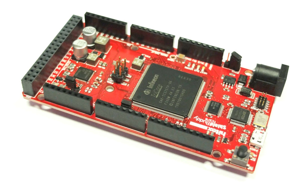
TC275 보드 소개
- ShieldBuddy TC275 보드
- Hitex 사에서 제작
- IDE 통합 개발 환경
보통 Editor, Compiler, Debugger를 핵심 기능으로 갖고 있다.
GPIO Sample Project
- 회로 몇 개만 좀 그려보자...
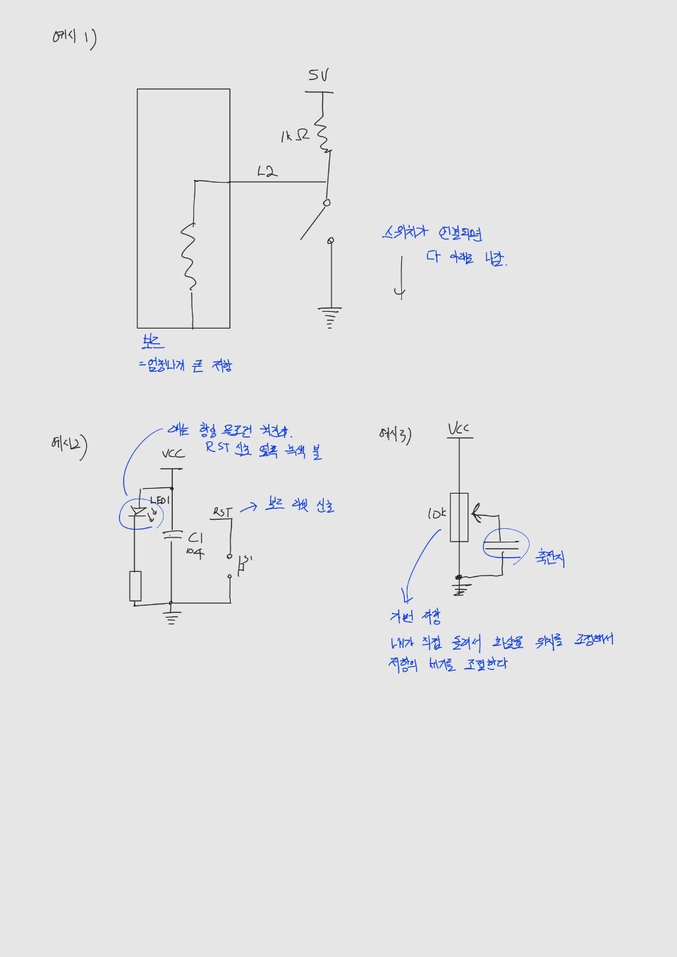
리셋 회로 질문좀 드리자(궁금증) 리셋 버튼 누르면 어떻게 되는지
리셋에 아무런 값이 인가되어있지 않다가 gnd와 연결되어서 reset 신호가 칩에 전달됨.
- 개발단계
- GPIO를 포함한 기능 구현 단계
회로파악 - 기능, HW 설정 - 핀/레지스터 설정 파악
uP(Microprocessor)의 어떤 핀을 어떻게 설정해야 하는지
Datasheet 참조 (중요!!!) - 코드 구현
User (Reference) Manual
- GPIO를 포함한 기능 구현 단계
LED 제어
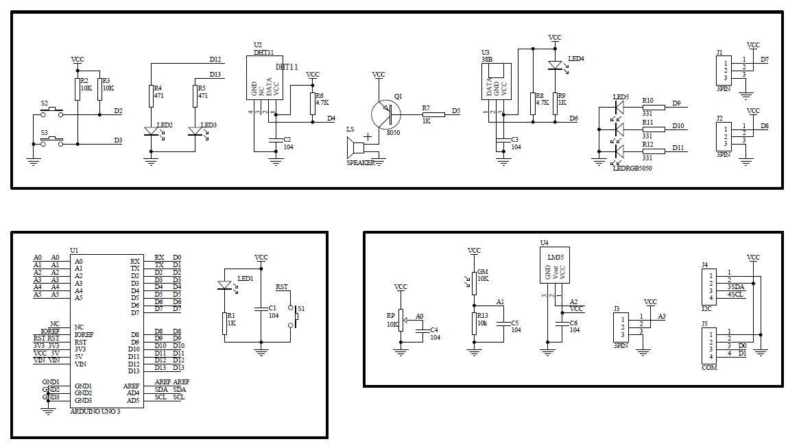
- 회로 파악
- D13을 제어하기 위해서는 uP의 어떤 핀을 제어해야 할까?
P10.2는 P = GPIO(General Purpose Input/Output), 10 = Group, 2 = Pin#을 의미 - 회로를 보니깐 high 신호를 줘야 LED가 켜진다. D12에 high를 줘야 Ground로 내려가면서 전류가 흐르겠다.
- D13을 제어하기 위해서는 uP의 어떤 핀을 제어해야 할까?
-
GPIO 레지스터 설정
-
p10.2를 출력 모드 동작으로 하기 위해서는 어떤 레지스터 설정?
어떤건 shieldbuddy를 보고 어떤건 d-step을 봐야 하지??(궁금증)
핀과 관련된 것을 보고 싶다 -> shieldbuddy
칩의 기능과 관련된 것을 보고 싶다 -> d-step

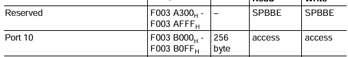
- IOCR을 찾기 위해 Port 10 Base address 확인
사실 다 define 되어있다. 연습하는 차원에서 참고.
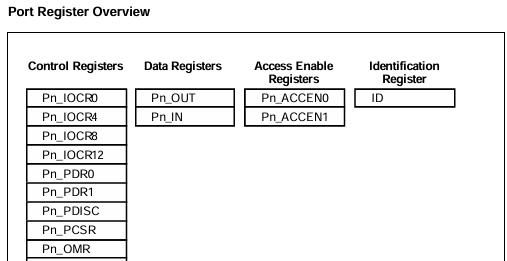
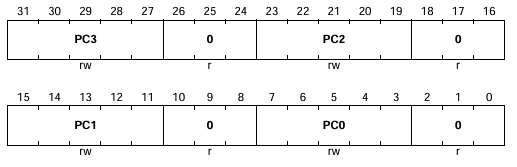
- Control을 위한 register 찾아보기
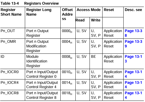
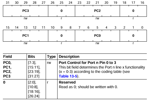
이 중에서 어떤 레지스터에 어떤 값? -> Register Pn_IOCR0 controls the Pn.[3:0] port lines
비트 5개 짜리도 레지스터라고 하는가? (궁금증) 정확히 어떤 것을 레지스터라고 지칭하는가?
노노 이 칩에서는 32비트가 register- Control을 위한 register 설정
0xF003B000 + 0x0010
0xF003B010
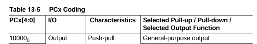
- P10.2를 output으로 설정
*(0xF003B010) |= 0x10 << 19 - P10.2를 초기화
*(0xF003B010) &= ~(0x1f << 19)
괄호 안의 식의 의미는 0...0111110...0
이걸 not 연산 하면 1...1000001...1 이거를 기존 레지스터와 and 연산 하면 레지스터의 원하는 PC2 부분만 0으로 초기화
초기화 후에 setting - 앞의 방법도 있지만 미리 정의된 Register를 사용하면 편리하다! 앞에서 말한것 처럼 이미 define 되어있다.
- 최종 초기화 코드
Register 뒤에 .U를 붙이는 것은 unsigned int로 접근하기 위함
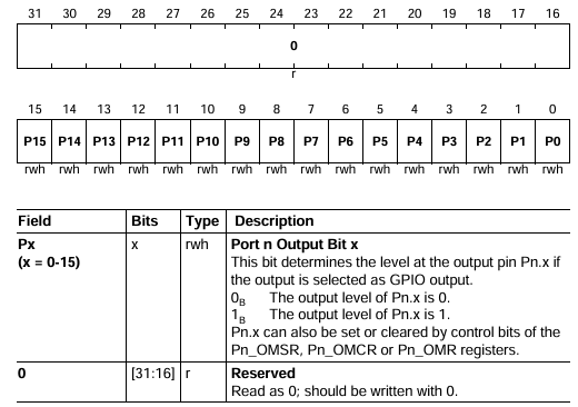
Register 초기화 후에 0x10으로 세팅 - P10.2에 출력값 설정 코드
Output register를 1로 설정하면 됨
- IOCR을 찾기 위해 Port 10 Base address 확인
-
- 전체 코드
#include "Ifx_Types.h"
#include "IfxCpu.h"
#include "IfxScuWdt.h"

#define PCn_2_IDX 19
#define P2_IDX 2

IfxCpu_syncEvent g_cpuSyncEvent = 0;

void initLED(void);


int core0_main(void)
{
    IfxCpu_enableInterrupts();

    /* !!WATCHDOG0 AND SAFETY WATCHDOG ARE DISABLED HERE!!
     * Enable the watchdogs and service them periodically if it is required
     */
    IfxScuWdt_disableCpuWatchdog(IfxScuWdt_getCpuWatchdogPassword());
    IfxScuWdt_disableSafetyWatchdog(IfxScuWdt_getSafetyWatchdogPassword());

    /* Wait for CPU sync event */
    IfxCpu_emitEvent(&g_cpuSyncEvent);
    IfxCpu_waitEvent(&g_cpuSyncEvent, 1);

    initLED();

    while(1)
    {
        P10_OUT.U = 0x1 << P2_IDX;
    }
    return (1);
}

void initLED(){
    P10_IOCR0.U &= ~(0x1F << PCn_2_IDX);
    P10_IOCR0.U |= 0X10 << PCn_2_IDX;
}
SW 제어(스위치 입력받는 프로젝트)
- 회로 파악
- S3를 제어해보자.
uP의 P2.1을 제어
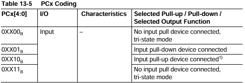
Pull-up 회로
D3가 1이면 눌리지 않고, 0이면 눌려있는 상태

- 추가 설명
Pull-up 회로: 위로 끌어당긴다. (기본 값이 1)
Pull-down 회로: 아래로 끌어당긴다. (기본 값이 0)
Sheildbuddy TC275 칩은 pull-up.
저항이 위 아래 아무 곳에도 연결되어 있지 않으면 open-drain
일반적으로는 noise나 충격에 강하므로 pull-up을 주로 사용
- S3를 제어해보자.
- GPIO 레지스터 설정
- P02.1을 입력 모드 동작으로 하기 위해서는 어떤 레지스터 설정?
출력과 마찬가지로 P02_IOCR을 입력으로 세팅
- P02_IOCR0을 ADR에 입력해보면 정의가 되어있으니 가져다 쓰도록 합니다.
- p02.1을 입력 모드 동작으로 세팅 코드
출력과 마찬가지로 P02_IOCR을 입력으로 세팅 - 읽어들이는 것은 Pn_IN register 사용
- P02.1을 입력 모드 동작으로 하기 위해서는 어떤 레지스터 설정?
- 전체 코드
#include "Ifx_Types.h"
#include "IfxCpu.h"
#include "IfxScuWdt.h"

#define PCn_2_IDX 19
#define P2_IDX 2
#define PCn_1_IDX 11
#define P1_IDX 1

IfxCpu_syncEvent g_cpuSyncEvent = 0;

void initGPIO(void);


int core0_main(void)
{
    IfxCpu_enableInterrupts();

    /* !!WATCHDOG0 AND SAFETY WATCHDOG ARE DISABLED HERE!!
     * Enable the watchdogs and service them periodically if it is required
     */
    IfxScuWdt_disableCpuWatchdog(IfxScuWdt_getCpuWatchdogPassword());
    IfxScuWdt_disableSafetyWatchdog(IfxScuWdt_getSafetyWatchdogPassword());

    /* Wait for CPU sync event */
    IfxCpu_emitEvent(&g_cpuSyncEvent);
    IfxCpu_waitEvent(&g_cpuSyncEvent, 1);

    initGPIO();

    while(1)
    {
        if((P02_IN.U & (0x1 << P1_IDX)) == 0){
            P10_OUT.U |= 0x1 << P2_IDX;
        }
        else{
            P10_OUT.U |= 0x0 << P2_IDX;
        }
    }
    return (1);
}

void initGPIO(){
    P02_IOCR0.U &= ~(0x1F << PCn_1_IDX);
    P02_IOCR0.U |= 0x02 << PCn_1_IDX;

    P10_IOCR0.U &= ~(0x1F << PCn_2_IDX);
    P10_IOCR0.U |= 0x10 << PCn_2_IDX;
}
실습
- 실습1) LED 하나 더 제어하기
#include "Ifx_Types.h"
#include "IfxCpu.h"
#include "IfxScuWdt.h"

#define PCn_2_IDX 19
#define P2_IDX 2
#define PCn_1_IDX 11
#define P1_IDX 1

IfxCpu_syncEvent g_cpuSyncEvent = 0;

void initGPIO(void);

int core0_main(void)
{
    IfxCpu_enableInterrupts();

    /* !!WATCHDOG0 AND SAFETY WATCHDOG ARE DISABLED HERE!!
     * Enable the watchdogs and service them periodically if it is required
     */
    IfxScuWdt_disableCpuWatchdog(IfxScuWdt_getCpuWatchdogPassword());
    IfxScuWdt_disableSafetyWatchdog(IfxScuWdt_getSafetyWatchdogPassword());

    /* Wait for CPU sync event */
    IfxCpu_emitEvent(&g_cpuSyncEvent);
    IfxCpu_waitEvent(&g_cpuSyncEvent, 1);

    while(1)
    {
        if(P02_IN.U & (0x1 << P1_IDX) == 0){
            P10_OUT.U = 0x1 << P1_IDX;
        }
        else{
            P10_OUT.U = 0x1 << P2_IDX;
        }
    }
    return (1);
}

void initLED(){
    P02_IOCR0.U &= ~(0x1F << PCn_1_IDX);
    P02_IOCR0.U |= 0x02 << PCn_1_IDX;

    P10_IOCR0.U &= ~(0x1F << PCn_2_IDX);
    P10_IOCR0.U |= 0X10 << PCn_2_IDX;
    P10_IOCR0.U &= ~(0x1F << PCn_1_IDX);
    P10_IOCR0.U |= 0x10 << PCn_1_IDX;
}- 실습 2) LED 토글시키기
#include "Ifx_Types.h"
#include "IfxCpu.h"
#include "IfxScuWdt.h"

#define PCn_2_IDX 19
#define P2_IDX 2
#define PCn_1_IDX 11
#define P1_IDX 1

IfxCpu_syncEvent g_cpuSyncEvent = 0;

void initGPIO(void);

int core0_main(void)
{
    IfxCpu_enableInterrupts();

    /* !!WATCHDOG0 AND SAFETY WATCHDOG ARE DISABLED HERE!!
     * Enable the watchdogs and service them periodically if it is required
     */
    IfxScuWdt_disableCpuWatchdog(IfxScuWdt_getCpuWatchdogPassword());
    IfxScuWdt_disableSafetyWatchdog(IfxScuWdt_getSafetyWatchdogPassword());

    /* Wait for CPU sync event */
    IfxCpu_emitEvent(&g_cpuSyncEvent);
    IfxCpu_waitEvent(&g_cpuSyncEvent, 1);

    static unsigned int prev;
    static unsigned int now;

    while(1)
    {
        now = P02_IN.U & (0x1 << P1_IDX) == 0;
        if(now && !prev){
            P10_OMR.U = 0x20002;
        }
        prev = now;
    }
    return (1);
}

void initLED(){
    P02_IOCR0.U &= ~(0x1F << PCn_1_IDX);
    P02_IOCR0.U |= 0x02 << PCn_1_IDX;

    P10_IOCR0.U &= ~(0x1F << PCn_1_IDX);
    P10_IOCR0.U |= 0x10 << PCn_1_IDX;
}- 버튼이 한번만 눌린것을 판별하려면 어떻게 해야할까?
- 이전의 상태랑 현재 상태를 저장을해서 다를 때만 바꾸는 것이다.
- 현재 0이 되었으면 1이 될때까지 무한 loop -> deadlock에 걸릴 수도 있다. (왜그렇지?) 여기서는 안걸린다. 더 복잡한 구조에서 걸릴 수 있다.
- cnt 값이 threshold(한계점) 이상이면
1번 2번을 보통 사용한다. 1번이 최고. 참고 - delay는 너무 커도 문제고 너무 작아도 문제 => 가장 선호되지 않는 방법
-
변수는 한번에 하나씩 따로 선언해라
unsigned char preSW, curSW; -> 이렇게 하지마 -
코드 한줄에 다섯 클락에서 열 클락 정도 사용한다.
while문 열클락
따라서 while문 안쪽이 총 30클락 정도
3번째 예시 150 ms 안에 눌렀다 때지 않는 이상 잘 동작한다는 거죠
10초 이상 누르면 integer overflow 난다는 거지(질문) -> max가 되면 wrap around가 일어나서 (0부터 다시 시작) unsigned int이기 때문에.
cnt 값이 1000안쪽에 들어올 수 있다. -
1번 2번을 보통 사용한다.
1번이 최고.
참고 - delay는 너무 커도 문제고 너무 작아도 문제 => 가장 선호되지 않는 방법 -
이런 레지스터들은 매 사이클 마다 계속 알아서 초기화해서 비트를 계속 안 초기화해줘도 된다.
원래는 이런것도 datasheet에 명시가 되어있는데 얘는 워낙 유명해서 안돼있는거같다...?
read as 0가 초기화된다는 의미인 것 같다.
