Assembler
Translating and Starting a Program
not readable
Translation Hierarchy
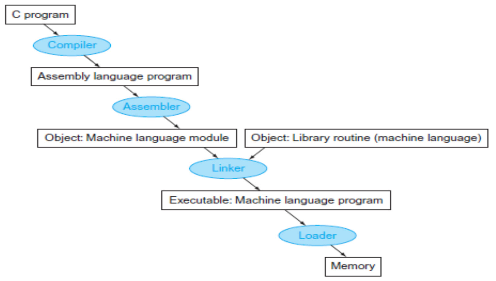
compiler -> Assembler -> Linker -> Loader
some steps can be compiled or skipped
What is “Assembler”?
- System S/W for turning programs written in assembly language to machine codes (i.e., object files, named xxx.o)
- Assembly language is a symbolic form of what the machine understands
- An object file is a combination of machine language instructions, data, and information needed to place instructions properly in memory
- There are certain fundamental functions that any assembler must
perform- Translating mnemonic operation codes to their machine language equivalents via opcode table
- Assigning machine addresses to symbolic labels used by the programmer
- The assembler must determine the addresses corresponding to all labels
- Assemblers keep track of labels used in instructions through a symbol table (which is a table that matches names of labels to the memory addresses that instructions/data occupy)
- 어셈블리어로 작성된 프로그램을 machine codes로 전환하기 위한 System S/W (예: object files, xxx.o)
- 어셈블리 언어는 기계가 이해하는 것의 상징적 형태이다.
- 객체 파일은 기계 언어 명령, 데이터 그리고 정보를 조합한 것으로, 명령을 메모리에 올바르게 배치하는 데 필요하다.
- 조립자가 반드시 수행해야 하는 몇 가지 기본 기능이 있다.
- opcode 테이블을 통한 mnemonic operation codes를 machine language로 번영
- 프로그래머가 사용하는 symbolic labels에 machine address 할당
- 어셈블러는 모든 레이블에 해당하는 주소를 결정해야 한다.
- 어셈블러는 a symbol table(라벨의 이름을 명령/데이터가 차지하는 메모리 주소에 일치시키는 테이블)을 통해 명령에 사용된 레이블을 추적한다.
machine language instructions, data, and information -> memory loading information 변환
opcode table: mnemonic operation codes->machine language
symbolic labels에 machine address 할당
모든 레이블에 해당하는 주소 결정
symbol table을 통해 memory address의 이름을 알 수 있다.
Assembler & Its Machine Dependency
- If we consider only such fundamental functions, most assemblers are
very much alike. - However, the features and design of an assembler depend heavily upon machine architecture, such as instruction formats and addressing modes -> Machine Dependent Features
- Let’s begin by considering the design of a basic assembler for the
standard version of our Simplified Instructional Computer (SIC)- Figure 2.1 in the next few slides shows an assembler language program
- 우리가 그러한 기본적인 기능만을 고려한다면, 대부분의 assembler들은 매우 비슷하다.
- 그러나 어셈블러의 기능과 디자인은 명령 형식 및 주소 지정 모드와 같은 machine architecture에 크게 좌우된다. -> Machine Dependent Features
- 먼저 SIC(Simplified Instructional Computer)의 표준 버전의 기본 조립기 설계를 고려해보자.
- 다음 몇 개의 슬라이드의 그림 2.1은 어셈블러 언어 프로그램을 보여준다.
Machine Dependent Features
SIC Assembler
SIC Assembler Language Program (Fig. 2.1, as an example)
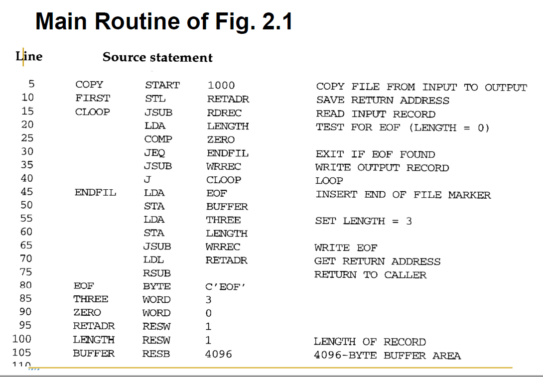
- The line numbers are for reference only and are not part of the program
- The mnemonic instructions used are those introduced in Chapter 1 and Appendix A
- Indexed addressing is indicated by adding the modifier “,X” following the operand (see line 160 in the next slides)
- STCH BUFFER, X
- Lines beginning with “.” contain comments only (see lines 110, 115, 120 and 195, 200, 205)
- 라인 번호는 참조용일 뿐 프로그램의 일부가 아니다.
- 사용된 mnemonic instructions는 1장 및 부록 A에서 소개되었다.
- 피연산자 뒤에 수식자 ",X"를 추가하여 Indexed Addresssing을 나타냅니다(다음 슬라이드의 행 160 참조).
- STCH BUFFER, X
- "."로 시작하는 행에는 주석만 포함된다.(110, 115, 120, 195, 200, 205행 참조).
- In addition to the mnemonic machine instructions, the following
assembler directives are used:- START: Specify name and starting address for the program
- COPY START 1000
- END: Indicate the end of the source program and (optionally) specify the first executable instruction in the program
- FIRST STL RETADR
....
END FIRST
- FIRST STL RETADR
- START: Specify name and starting address for the program
- mnemonic machine instructions 외에 다음 assembler directives도 사용된다 :
- 시작: 프로그램의 이름 및 시작 주소 지정
- COPY START 1000
- 종료: 소스 프로그램의 끝을 표시하고 (선택 사항) 프로그램의 첫 번째 실행 명령을 지정한다.
- FIRST STL RETADR
....
END FIRST
- FIRST STL RETADR
- 시작: 프로그램의 이름 및 시작 주소 지정
START: start memory address, default start address = 0 value, optional으로 써도 되고 안써도 된다.
END: symbolic, 꼭 써야만 한다. end operand를 통해 first instruction을 나타낼 수 있다.
- BYTE: Generate character or hexadecimal constant, occupying as many bytes as needed to represent the constant
- EOF BYTE C’EOF’
- INPUT BYTE X’F1’
- WORD: Generate one-word integer constant
- THREE WORD 3
- RESB: Reserve the indicated number of bytes for a data area
- BUFFER RESB 4096
- RESW: Reserve the indicated number of words for a data area
- RETADR RESW 1
- Directives are NOT translated into machine instructions.
- Instead, they provide instructions to the assembler itself.
- BYTE: 문자 또는 16진수 상수를 생성한다. 상수를 나타내는 데 필요한 바이트 수만큼 차지한다.
- EOF BYTE C’EOF’
- INPUT BYTE X’F1’
- WORD: 한 단어 정수를 생성한다.
- THREE WORD 3
- RESB: 데이터 영역에 대해 표시된 바이트 수를 예약한다.
- BUFFER RESB 4096
- RESW: 데이터 영역에 대해 표시된 단어 수를 예약한다.
- RETADR RESW 1
- Directives은 machine instruction으로 변환되지 않는다.
- 대신 어셈블러 자체에 instruction을 제공한다.
중요. Directives are NOT translated into machine instructions. 명령을 내리기 위한 statement이기 때문이다. directive는 assembler가 실행할 instruction.
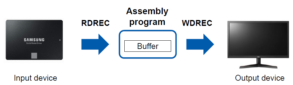
- The program contains a main routine that reads records from an input device (identified with device code F1) and copies them to an output device (identified with device code 05)
- This main routine calls the two subroutines:
- RDREC to read a record into a buffer (= 4096 bytes)
- WRREC to write the record from the buffer to the output device
- 이 프로그램에는 입력 장치(장치 코드 F1로 식별됨)에서 레코드를 읽고 출력 장치(장치 코드 05로 식별됨)로 복사하는 a main routine이 포함되어 있다.
- 이 주요 루틴은 두 개의 서브루틴을 호출한다.
- RDREC: 레코드를 버퍼로 읽는다. (= 4096바이트).
- WREC 버퍼에서 출력 장치로 레코드 쓴다.
입력 장치에서 레코드 읽고 출력 장치에 출력
RDREC -> buffer -> WDREC
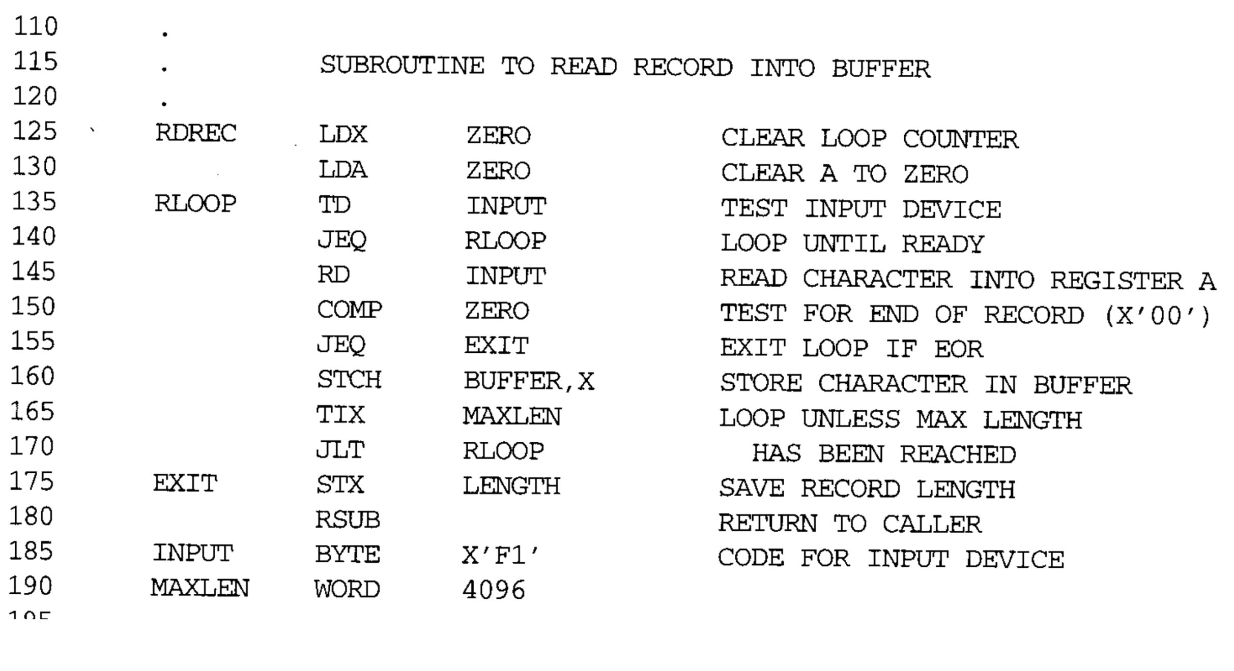
- Each subroutine must transfer the record one character at a time because the only I/O instructions available are RD and WD
- Each record consists of several characters
- The end of each record is marked with a null character (hexadecimal 00)
- The buffer is necessary due to different I/O rates between input and output devices
- 사용 가능한 I/O 명령은 RD 및 WD뿐이므로 각 서브루틴은 한 번에 한 문자씩 레코드를 전송해야 한다.
- 각 레코드는 여러 문자로 구성된다.
- 각 레코드의 끝에는 null 문자(16진수 00)가 표시된다.
- 입력 장치와 출력 장치 간에 I/O 속도가 다르기 때문에 buffer가 필요하다.
사용 가능한 I/O 명령: RD, WD. 서브루틴은 한 번에 한 문자씩 레코드 전송
레코드는 여러 문자로 구성
각 레코드의 끝에는 null 문자
입출력 간에 I/O 속도가 달라서 buffer 필요.
buffer에 한 번 저장. record라는 데이터를 옮긴다고 가정하자. 여러 캐릭터로 구성된 데이터 sequence가 있아다. input device에 어떤 파일이 있고 여러 record가 있고 record가 여러 캐릭터로 구성되었다. 각 record의 끝을 null char로 표시한다. null char은 00, 1byte로 표시하게 된다.
rdrec으로 읽고 wdrec으로 쓴다. 내부적으로 rd와 wd만 사용 가능하다. record에서도 한 번에 한 바이트의 데이터만 읽거나 쓸 수 있다.
iteration 돌면서 한 번에 한 바이트씩 옮긴다.
buffer가 사용되어야 하는 이유는 input device와 output device 속도가 달라질 경우 데이터 손실이 날 수 있기 때문이다. io device can handle 1byte/sec. input device can write 10bytes/sec. 한 바이트 처리하는 동안 9 바이트는 드랍될 수 있다. 저장해둘 memory space가 필요한데 그것이 buffer이다. buffer에 저장해두고 output device에 쓴다. 이것을 buffering이라고 하고 input device와 output device 차이 처리 속도의 gap을 buffer 사이즈만큼 완화시킨다.
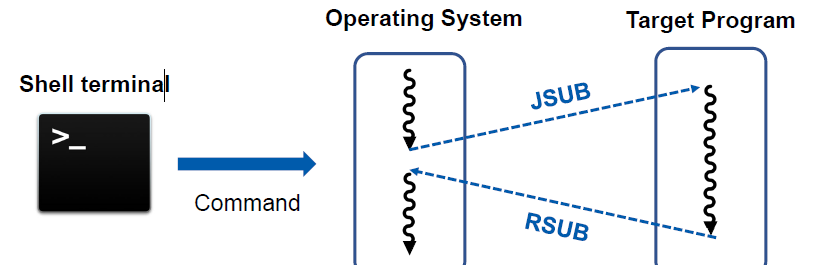
- When the end of file is detected, the program writes EOF on the output device and terminates by executing an RSUB instruction
- We assume that the program was called by the OS using a JSUB instruction
- JSUB m ? L <- (PC); PC <- m
- So, the RSUB will return control to the OS
- RSUB ? PC <- (L)
- We assume that the program was called by the OS using a JSUB instruction
- 파일의 끝이 감지되면 프로그램은 출력 장치에 EOF를 쓰고 RSUB 명령을 실행하여 종료한다.
- 우리는 프로그램이 JSUB 명령을 사용하여 OS에 의해 호출되었다고 가정한다.
- JSUB m? L <- (PC); PC <- m
- 따라서 RSUB는 OS에 대한 제어권을 반환합니다.
- RSUB? PC <- (L)
- 우리는 프로그램이 JSUB 명령을 사용하여 OS에 의해 호출되었다고 가정한다.
register L, register PC
copy pc into register m
register address value which indicates
operating system will find
execute jsub.
code flow can be jump to target program. terminate.
excute rsub.
copy to the register pc. code flow can be jumpped to here again.
언젠가는 파일의 끝을 만나게 된다. EOF을 만나게 되면 프로그램은 output device에 eof를 또 써야 한다. 더 이상 input device에 읽을 데이터가 없다. eof를 만나면 eof로 output device에 써주고 rsub instruction을 사용해서 사용한다. programming operating system에 의해 시작됐다고 가정해서 rsub을 쓴다.
operating system은 target programd.
register L에 return address 저장. jsub을 통해 target program instruction을 시작한다.
instruction을 시작하고 나면 target program이 종료되는 시점이 있다. 그때 rsub instruction을 써서 return address를 pc에 copy하고 operating system이 시작한다. 그러면 code flow가 jump하는 효과가 있다.
Main Routine of Fig. 2.1 (참고)
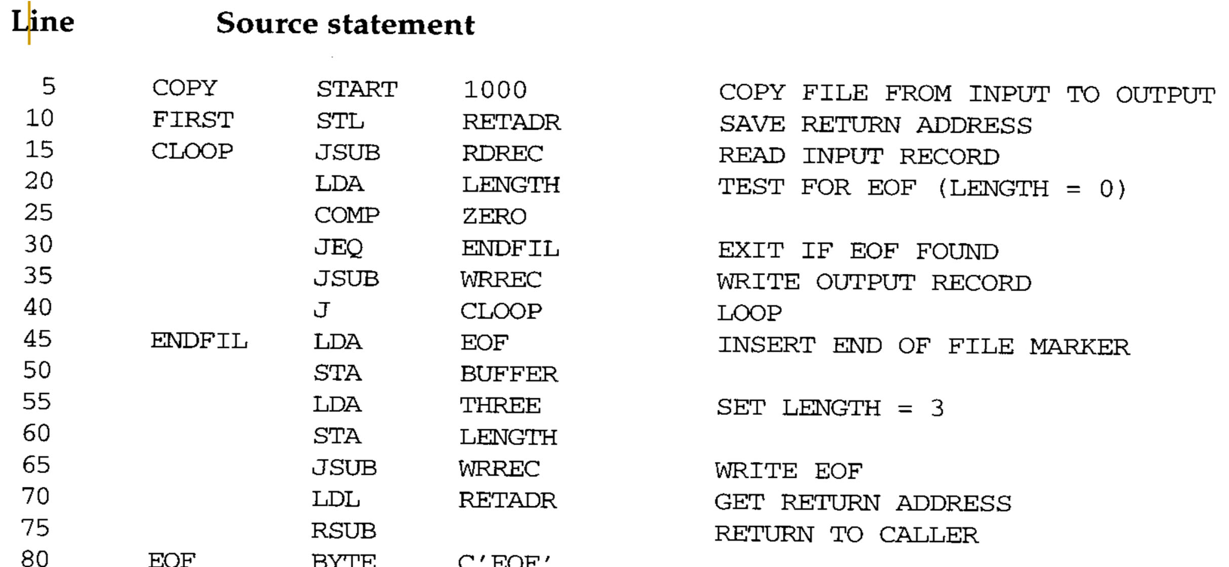
Line: code line number. reference only. not part of this program
Source statement : Source
Main Routine of Fig. 2.1

copy program name, 1000 start address.
start address this one
register L
10번째 줄
register L은 return address를 memory location에 저장해둔다. main routine이 sub routine을 invoke할 때 사용한다. register L이 다른 값으로 바뀐다. operating system으로 부터 받은 return address를 저장해두어야 해서 stL을 메모리 location에 저장해둔다.
rdrec routin. input device 읽으면 가장 오른쪽 8비트에 저장된다. register a값이 0과 같은지 비교한다. 읽은 데이터가 record의 끝을 나타내는 0 char이면 비교 결과가 =이 될 것이다. 읽은 데이터가 어떤 값이면 register a 값이 0보다 클테니까 > 를 가지게 된다. comp instruction을 통해서 end of record를 만났나 안만났나 체크한다. rdrec subroutine에서 나가야 한다. jeq instruction을 통해 stx로 jump한다. 읽은게 eorecord가 아니면 읽은 데이터를 buffer를 저장한다. 이때 indexed addressing을 한다. 버퍼 앞부분부터 데이터를 채운다. tix를 통해 register x값이 1 증가하고 증가한 값이 maxlen과 큰지 작은지 비교한다. maxlen은 버퍼의 전체 크기를 의미한다. x register가 1 byte를 읽을때마다 증가한다. rd instruction을 수행하고 tix를 수행한다. 읽은 데이터의 총 크기라고 생각해야 한다. 읽은 데이터의 크기가 buffer보다 크면 안된다. 즉, tix를 통해 buffer에 남은 공간이 있냐없냐를 확인한다. 첫 intu..에서는 1byte만 저장해서 남은 결과가 있고 less가 될 것이고 원점(rloop)으로 돌아가서 다시 instruction을 다시 시작한다. 다음 데이터를 input device에 읽어서 버퍼에 저장한다. 마찬가지로 buffer가 가득 찼다 (maxlen과 동일하면 rdrec을 종료해야 한다. stx instruction을 시작한다.
stx는 end of record를 만나거나 buffer가 가득 찼을 때 시작된다. register x에 저장된 input data의 크기를 ~에 저장하고 rsub를 한다. 다음 코드는 LDA부터 시작을 하게 될 것이다.
j로 돌아감.... lenght value will be zero.
comp zero, code flow will be jump LDA. terminate by excuting rsub instruction. program will load EOF to register A.
EOF transfer to the buffer area.
this program also copy constant 3 to the register a
buffer EOF, a constant number 3.
by using buffer, length. we can invoke r..subroutine
우리가 RLEC을 호출하고 무조건 cloop으로 점프한다. rdrec과 wrrec을 수행해서 input record를 output으로 copy한다. 언젠가는 input device로부터 EOF를 만난다. 그런 경우에는 output device에 EOF를 써서 알려주어야 한다. 그래서 EOF를 만나게 되면 rdrec를 호출하고 나서 length에 0이 있을 것이다. 읽어들인 데이터의 크기가 0이라는 뜻이다. comp로 zero와 같은지 확인한다. 비교결과가 jeq에 따라 아래 코드로 jump한다.
나머지 코드에서는 eofchar를 buffer에 이동한다. buffer에는 eof가 적혀있다. three가 eof char의 크기이다. wirte에 3이란 값을 length에 쓴다. rdrec에서는 버퍼에 저장하고 길이를 length에 저장했다. 같은 것을 4가지 인스트럭에서 한다.
buffer에는 EOF, length에는 3이 저장한다. wrec을 호출해서 3개의 char을 output device에 write한다.
초반에 operating systemd으로부터 받은 return address를 받아서 rsub를 실행한다. code flow는 os로 다시 넘어간다.
Subroutine RDREC of Fig. 2.1
135, 140
X, A 0 value. using two instruction. subroutine will check input device is ready. if filled
this repeated until device is ready
145
rd.
JEQ에서 jump. STX로.
160
buffer is full. subroutine face end of record. this subroutine will execute this instruction.
(stx) register x value means
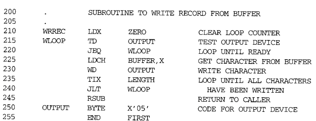
Subroutine WRREC of Fig. 2.1
tix instruction. increase by 1. change to zero to one ...
X is length value. input value..
wrec도 rdrec과 비슷한 로직 ldx 0으로 초기화. output device가 준비 됐는지 td, jeq로 확인한다. 준비됐으면 뒤로 가고 준비가 안됐으면 반복해서 체크할 것이다. rdrec logic과 동일하다. target device만 달라진다.
그리고 나서 rdch instruction을 통해서 1 byte data를 .. wd로 output을 기록할 것이다. indexed addressing을 사용하고 있다. buffer의 가장 첫 데이터부터 rdch를 통해 output에 write한다. tix로 output register 값을 0에서 1로 증가시킨다. 0과 1의 len값의 대소관계를 비교한다. rdrec에서 input data의 크기를 비교하기 위해 사용한다. rdrec에서 읽어들인 input data의 길이가 저장되어 있다. 그래서 바꾸어 말하면 buffer에 읽어들인 데이터가 10byte가 있는데 output device에 쓸 것이다. write할 input data 크기와 buffer 크기를 비교한다. 아직 1byte만 write한 것이고, length만큼 남았다. register x가 length보다 당연히 작다. less than symbol이다. register x가 length만큼의 크기를 썼다면 buffer에 write할 데이터가 남아있지 않다. 그 결과 equal symbol이 될 것이다. 그에 따라 jump할 방향이 달라진다. equal이라면 jlt jump 안하고 다음인 rsub를 실행한다. jump했다는 것은 버퍼에 write할 데이터가 남아있다는 것. 동일한 코드를 수행해서 output device에 write 해주어야 한다. buffer의 모든 데이터에 write하면 rsub에 돌아가서 코드 지점으로 돌아간다.
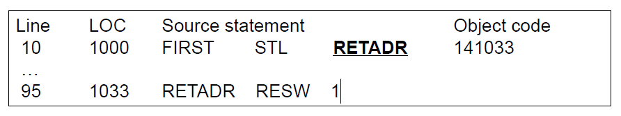
Fig. 2.2: Program from Fig. 2.1 with Object Code
- The same program as in Fig. 2.1, with the generated object code for each statement
- ‘Loc’ column gives the machine address (in hexadecimal) for each part of the assembled program
- The program is assumed to start at address 1000
- Several functions required to translate source program into object codes:
- 1) Convert mnemonic operation codes to their machine language equivalents
- [e.g., translate STL to 14 (line 10)]
- 2) Convert symbolic operands to their equivalent machine addresses -> [e.g., translate RETADDR to 1033 (line 10)]
- 3) Build the machine instructions in the proper format (w/ addressing mode)
- 4) Convert data constants specified in the source program into their internal machine representations -> [e.g., translate EOF to 454F46 (line 80)]
- 5) Write the object program and the assembly listing file -> [e.g., Fig. 2.3 shows the object program and the assembly listing is similar to Fig.2.2]
» An assembly listing file is used for checking how the program is translated
- 1) Convert mnemonic operation codes to their machine language equivalents
- ‘Loc’ column gives the machine address (in hexadecimal) for each part of the assembled program
- 각 문장에 대해 생성된 객체 코드가 있는 그림 2.1과 동일한 프로그램
- 'Loc' 열은 조립된 프로그램의 각 부분에 대한 기계 주소(16진수)를 제공한다.
- 프로그램은 주소 1000에서 시작하는 것으로 가정된다.
- 소스 프로그램을 객체 코드로 변환하는 데 필요한 몇 가지 기능:
- 1) mnemonic operation code를 machine language equivalent로 변환한다.
- [예: STL을 14(줄 10)로 변환]
- 2) symbol operands를 equivalent machine address로 변환합니다. -> [예: RETADDR을 1033(줄 10)로 변환]
- 3) machine instructions를 적절한 형식(주소 지정 모드 포함)으로 작성
- 4) 소스 프로그램에 지정된 data constants를 내부 기계 표현으로 변환 -> [예: EOF를 454F46(라인 80)으로 변환]
- 5) 객체 프로그램과 어셈블리 목록 파일을 작성한다. -> [예: 그림 2.3은 객체 프로그램을 나타내며 어셈블리 목록은 그림 2.2와 유사하다.]
» 어셈블리 목록 파일은 프로그램이 어떻게 번역되는지 확인하는 데 사용된다.
- 1) mnemonic operation code를 machine language equivalent로 변환한다.
- 'Loc' 열은 조립된 프로그램의 각 부분에 대한 기계 주소(16진수)를 제공한다.
LOC 열은 각 부분에 대한 기계 주소(16진수)를 제공
소스 프로그램을 object code로 변환하는 과정 잘 살펴 보기
- All of the functions above can easily be accomplished by sequential processing of the source program, one line at a time. However, the second function for translating addresses presents a problem!
- Consider the statement <line 10> -> This instruction contains a forward reference
- 위의 모든 기능은 소스 프로그램을 한 번에 한 줄씩 순차적으로 처리함으로써 쉽게 달성할 수 있다. 그러나 주소를 번역하는 두 번째 기능은 문제를 제기한다.
- <줄 10> -> 이 지침에는 forward reference 포함되어 있다.
forward reference
- Because of this, most assemblers make two passes over the source program:
- The 1st pass just scans the source program for label definitions while assigning addresses to the labels
- The 2nd pass performs most of the actual translation previously described
- 이 때문에 대부분의 어셈블러는 소스 프로그램을 두 번 통과한다.:
- The 1st pass는 소스 프로그램에서 레이블 정의를 스캔하는 동시에 레이블에 주소를 할당한다.
- The 2nd pass는 이전에 설명한 실제 번역의 대부분을 수행한다.
1nd pass: scan과 동시에 레이블에 주소 할당
2nd pass: 실제 번역 대부분 수행

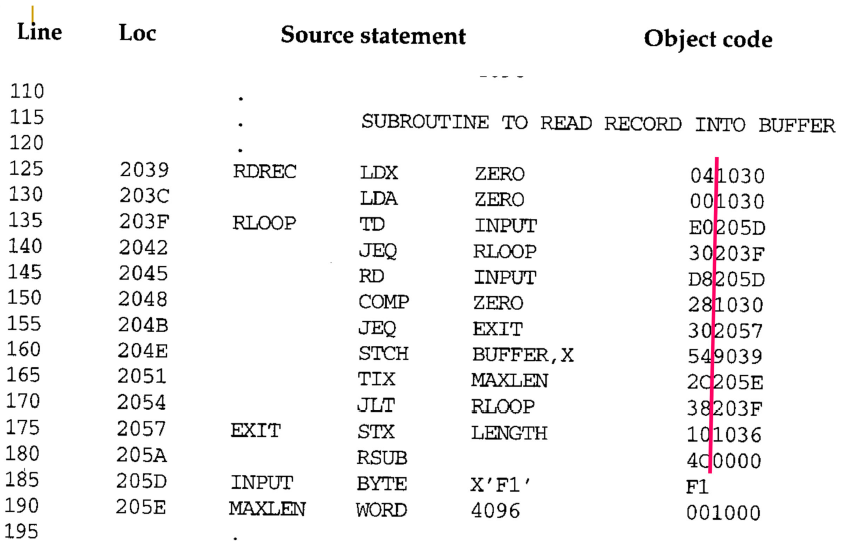
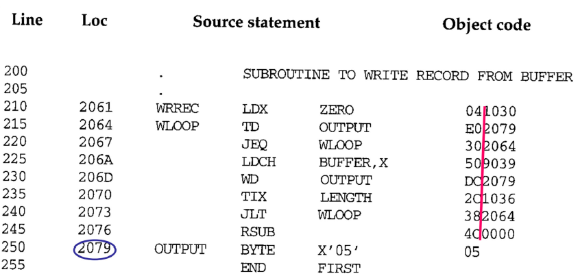
Fig. 2.3: Object Program corresponding to Fig. 2.2
- The assembler must write the generated object code into some output devices (i.e., storage), and then this object program will later be loaded into memory for execution
- The simple object program format used contains 3 types of records:
- Header record contains the program name, starting address, and length
- Text records contain the translated instructions and data of the program, together with an indication of the addresses where these are to be loaded
- End record marks the end of the object program and specifies the address in the program where execution is to begin
- 어셈블러는 생성된 객체 코드를 일부 출력 장치(예: 저장)에 기록해야 하며, 그러면 이 객체 프로그램은 나중에 실행을 위해 메모리에 로드될 것이다.
- 사용되는 단순 객체 프로그램 형식에는 다음과 같은 3가지 유형의 레코드가 포함되어 있다.
- Header reocrds에는 프로그램 이름, 시작 주소 및 길이가 포함된다.
- Text records에는 프로그램의 번역된 지침과 데이터가 로드될 주소의 표시와 함께 포함된다.
- End record는 객체 프로그램의 끝을 표시하고 실행을 시작할 프로그램의 주소를 지정한다.
object program
3가지 유형의 record: Header record, Text record, End record
Three Types of Records
- Header record
– Col. 1 H
– Col. 2-7 Program name
– Col. 8-13 Starting address of object program (hex)
– Col. 14-19 Length of object program in bytes (hex) - Text record
– Col. 1 T
– Col. 2-7 Starting address for object code in this record (hex)
– Col. 8-9 Length of object code in this record in bytes (hex)
– Col. 10-69 Object code, represented in hex (2 columns per byte of object
code) - End record
– Col.1 E
– Col.2-7 Address of first executable instruction in object program (hex)
Header record, Text record, End record
translate된 instruction은 text record에 포함된다. object code의 chunk가 저장된다.
format대로 record들이 구성되어 있다.
Fig. 2.3
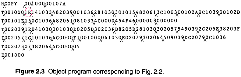
- The symbol ^ is used to separate fields visually
- Of course, such symbols are not present in the actual object program
- Note that there is no object code corresponding to addresses 1033-2038. This storage is simply reserved by the loader for use by the program during execution.
- ^ 기호는 필드를 시각적으로 구분하는 데 사용된다.
- 물론, 그러한 기호는 실제 객체 프로그램에는 존재하지 않는다.
- 주소 1033-2038에 해당하는 object code가 없다. 이 저장소는 실행 중에 프로그램에서 사용할 수 있도록 로더에 의해 예약된다.
크게 10개의 snipfet chunk. object 코드의 일부가 들어있다. figure 202에 보면 앞 10개가 text record에 들어가고 그 다음이 들어간다.
object코드가 어떤 시작 주소를 가질지. 메모리 코드 1000번째부터 오브젝트 코드가 로딩이 된다.
1033-2038의 메모리 주소 범위에는 오브젝트가 없다. resw와 resb로 나누어지는 영역. loader가 메모리 영역을 확보해준다. 얘에 대한 오브젝트 코드를 만들 필요가 없다. 아무 값도 없다. 0으로 초기화된 상태이다. resw나 resb에 대해서는 object 코드를 따로 만들지 않는다.
text record보면 1033-2038 범위에서 object 코드가 없는 것을 확인할 수 있다.
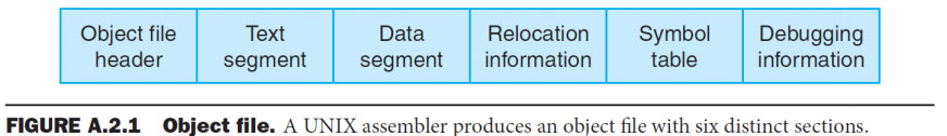
The Object File for UNIX
- The object file for UNIX systems typically contains 6 distinct pieces:
- Header, describing the size & position of the other 5 pieces of the object file
- Text Segment, containing the machine language code
- Static Data Segment, containing data allocated for the life of the program
- Relocation Information, identifying instructions and data words that depend on absolute addresses when the program is loaded into memory
- Symbol Table, containing <lable – address> information about function and
global variables - Debugging Information, containing symbolic information so that a debugger can associate machine instructions with C source files
- A concise description of how the program modules were compiled
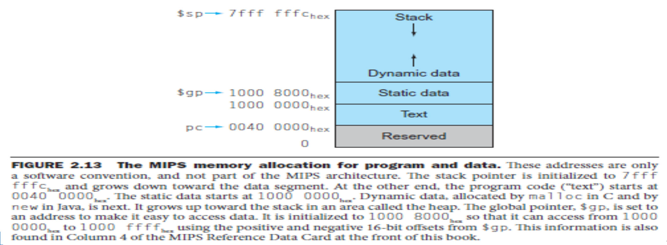
- UNIX allows programs to use both static data (allocated throughout the program) and dynamic data (which can grow or shrink as needed by the program)
- UNIX 시스템용 오브젝트 파일은 일반적으로 6개의 다른 부분으로 구성되어 있다:
- Header, 오브젝트 파일의 나머지 5개의 크기와 위치를 설명한다.
- Text Segment, 기계어 코드 포함
- Static Data Segment, 프로그램 수명 동안 할당된 데이터 포함
- Relocation Information, 프로그램이 메모리에 로드될 때 절대 주소에 따라 달라지는 지시사항 및 데이터
- Symbol Table, 기능에 대한 <lable – address> 정보가 들어 있습니다.
전역 변수 - Debugging Information, 기호 정보가 포함되어 있다. 디버거는 컴퓨터 명령어를 C 소스 파일과 연결할 수 있다.
- 프로그램 모듈이 컴파일된 방법에 대한 간결한 설명
- UNIX는 프로그램이 정적 데이터(프로그램 전체에 할당됨)와 동적 데이터(프로그램이 필요에 따라 증가 또는 축소할 수 있음)를 모두 사용할 수 있도록 한다.
Unix 시스템용 오브젝트 파일 : header, text segment, (static) data segment, relocation infromation, symbol table, debugging information
정적 데이터와 동적 데이터 모두 사용
2-pass Assembler
- Pass 1: Define symbols
- Read a statement in a line of assembly code
- Assign an address to this statement: increasing the address by N (word addressing or byte addressing) using LOCCTR (location counter)
- Save address values assigned to all labels (in symbol tables) for use in pass 2
- Perform some processing of assembler directives, such as constant declaration or space reservation
- This includes processing that affects address assignment, such as determining the length of data areas defined by BYTE, RESW, etc.
-> Pass1 usually writes an intermediate file that contains each source statement together with its assigned address, error indicators, etc.
- Pass 1: symbols 정의
- assembly code 줄에서 statement 읽기
- statement에 주소 할당 : LOCCTR(위치 카운터)을 사용하여 주소를 N(단어 주소 지정 또는 바이트 주소 지정)만큼 늘린다.
- 주소 값 저장은 Pass 2에서 사용할 수 있도록 모든 레이블(심볼 테이블)에 할당된다.
- 정수 선언 또는 공간 예약과 같은 어셈블리 명령의 일부 처리 수행
- 여기에는 BYTE, RESW 등으로 정의된 데이터 영역의 길이를 결정하는 등 주소 할당에 영향을 미치는 처리가 포함된다.
-> Pass1은 일반적으로 할당된 주소, 오류 표시기 등과 함께 각 소스 문을 포함하는 intermediate file을 작성합니다.
2-pass algorithm. after assign
pass 1: symbols 정의
statement 읽기
주소 할당
주소값 저장
일부 처리
- Pass 2: Assemble instructions & generate object program
- Read in a line of code: Intermediate file created in the 1st pass is used as the input to the 2nd pass
- Translate operation code, using OP Code Table
- Change labels to addresses, using Symbol Table
- Perform processing of assembler directives not done during pass 1
- Produce object program
- 통과 2: 지침 조립 및 객체 프로그램 생성
- 코드 한 줄 읽기: 첫 번째 패스에서 생성된 중간 파일이 두 번째 패스에 대한 입력으로 사용된다.
- OP Code Table을 사용하여 작업 코드 변환
- Symbol Table을 사용하여 레이블을 주소로 변경
- Pass 1 동안 수행되지 않은 조립자 지시사항 처리 수행
- 객체 프로그램 생성
pass2: assemble instructions & generate object program
op code table로 작업 코드 변환
symbol table 사용하여 레이블을 주소로 변경
pass1 동안 수행되지 않은 assemble directive 수행
Two Data Structures of SIC Assembler
Operational Code Table (OPTAB)
- Contain mnemonic op code and its machine language equivalent.
- Also, it may contain variable-sized instruction format and length (for more complex
assemblers)
- Also, it may contain variable-sized instruction format and length (for more complex
- In Pass 1, it is used to look up and validate mnemonic codes.
- In Pass 2, used to translate the op codes to machine language.
- Usually organized as a hash table
- Key: mnemonic code
- Fast retrieval with a minimum of searching
- Once prepared, the OPTAB is not changed.
- Operational Code Table (OPTAB)
- mnemonic op code와 해당 기계어에 해당하는 코드를 포함한다.
- 또한 가변 크기의 명령 형식과 길이를 포함할 수 있다. (더 복잡한 경우).
조립자)
- 또한 가변 크기의 명령 형식과 길이를 포함할 수 있다. (더 복잡한 경우).
- Pass 1에서는 mnemonic 코드를 조회하고 검증하는 데 사용된다.
- Pass 2에서 op codes를 machine language로 변환하는 데 사용된다.
- 일반적으로 hash table로 구성됨
- Key: mnemonic code
- 최소한의 검색으로 빠른 검색
- 일단 준비되면 OPTAB는 변경되지 않는다.
OPTAB
mnemonic op code, 해당 기계어 해당 코드 포함
pass 1에서는 mnemonic 코드 조회 검증
pass 2에서 op codes를 machine language로 변환
hash table 구성
readonly data structure
symbol table을 만든다.
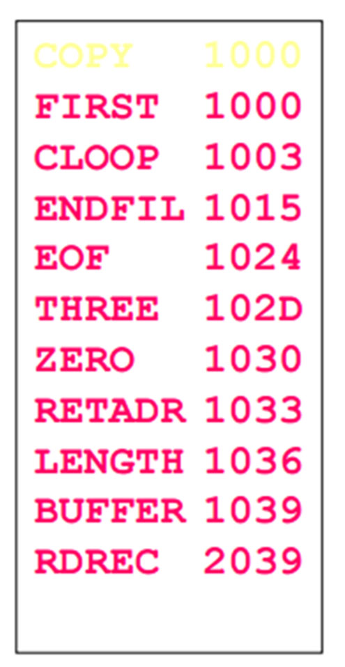
Symbol Table (SYMTAB)
- Include name and value (address) for each label in the source program, together with flags (error condition).
- Also, it may contain other information such as a type or a length.
- In Pass 1, labels are entered into SYMTAB with their assigned addresses (from LOCCTR : location counter).
- In Pass 2, symbols used as operands are looked up in SYMBOL to obtain the addresses to be inserted in the assembled instructions.
- Usually hash table
- efficient insertion and retrieval are needed.
- 플래그(오류 조건)와 함께 소스 프로그램의 각 레이블에 대한 이름 및 값(주소)을 포함한다.
- 또한, 유형 또는 길이와 같은 다른 정보를 포함할 수 있다.
- Pass 1에서 라벨은 할당된 주소와 함께 SYMTAB에 입력된다(LOCCTR: 위치 카운터).
- Pass 2에서는 피연산자로 사용되는 기호를 기호에서 찾아 조립된 명령어에 삽입될 주소를 얻는다.
- 보통 해시 테이블
- 효율적인 삽입 및 검색이 필요하다.
symbol table
flag와 name and value 포함
pass 1에서 라벨은 할당된 주소와 함께 SYMTAB에 입력
pass 2에서 삽입될 주소 얻음
hash table
object file for unix
프로그램을 로드하면 space를 용도에 따라 여러 영역으로 나누어준다. 프로그램 코드 사이에서 정의된 .. 나머지 공간에서 program num time.. malloc된 데이터가 dynamic data. stack에는 local variable들이 저장된다.
중간 파일이 pass2에서 input이 된다.
mapping된 정보를 갖는다. symbol table로 operand로 사용하는 symbol 데이터를 번역하는데 사용.
Fig. 2.4(a)
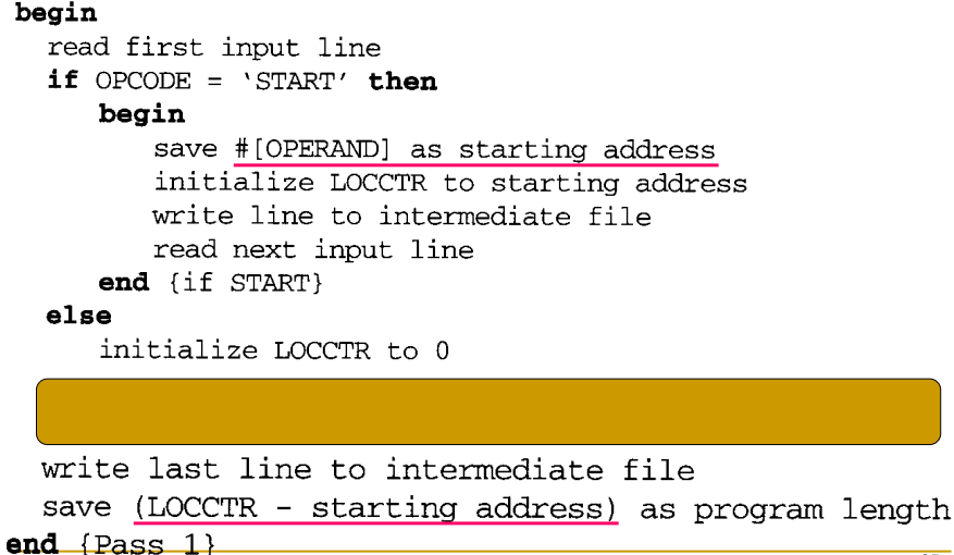
만약 start directive가 없으면 0으로 초기화되어 0으로 시작된다. 읽어드린 input line을 intermediate file에 변경 없이 작성한 후 다음 input line을 읽어들인다.
input line은 박스에서 처리된다.
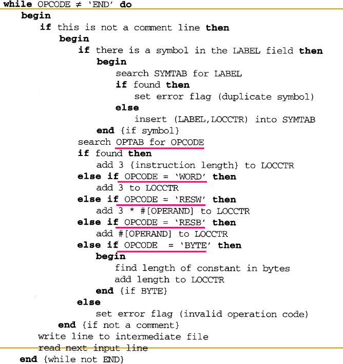
input line이 end directive가 아닌 동안에는 모든 input line을 처리할 것이다. comment line이 아니면 lable field에 symbol이 있는지 확인한다. 3가지 filed (label,operand,opcode)가 있다. label은 symbolic label이 있는지 정의, 있으면 table을 찾아본다. 이미 있다면 중복 처리를 하고, 처음 만난 symbol이면 symbol에 대한 mapping정보를 symbol table에 넣어준다. 할당을 할 address value가 있고 label에 배치해서 넣어준다.
opcode filed에 있는 값을 본다. opcode field에는 directive가 있을 수 있다. opcode에선 instruction code만큼 .. resb이면 byte 값만큼 더해준다. 이 코드를 통해서 location counter를 업데이트해준다. 다음 value로.
모두 아니라면 invalid, error flag를 처리한다.
해당 line을 수정하지 않고 intermediate file.
마지막에는 file에 쓰고 program length를 계산한다.
Fig. 2.4(b)
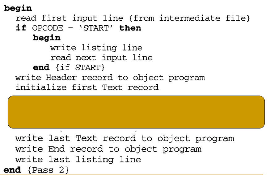
pass-2 algorithm.
pass01이 만든 intermediate file이 input
start directive인지 확인하고 맞으면 assembly listing line에 그대로 써준다.
source statement의 assign value와 statement가 포함됨.
다음 input line을 읽어들인다.
그리고 header record를 만드는데, program name이나 start length 등의 정보를 pass-1에서 찾았다. start directive로부터 start address를 가져왔고. start name도 가져옴. header record를 만들고 이제 text record를 만들 준비를 한다.
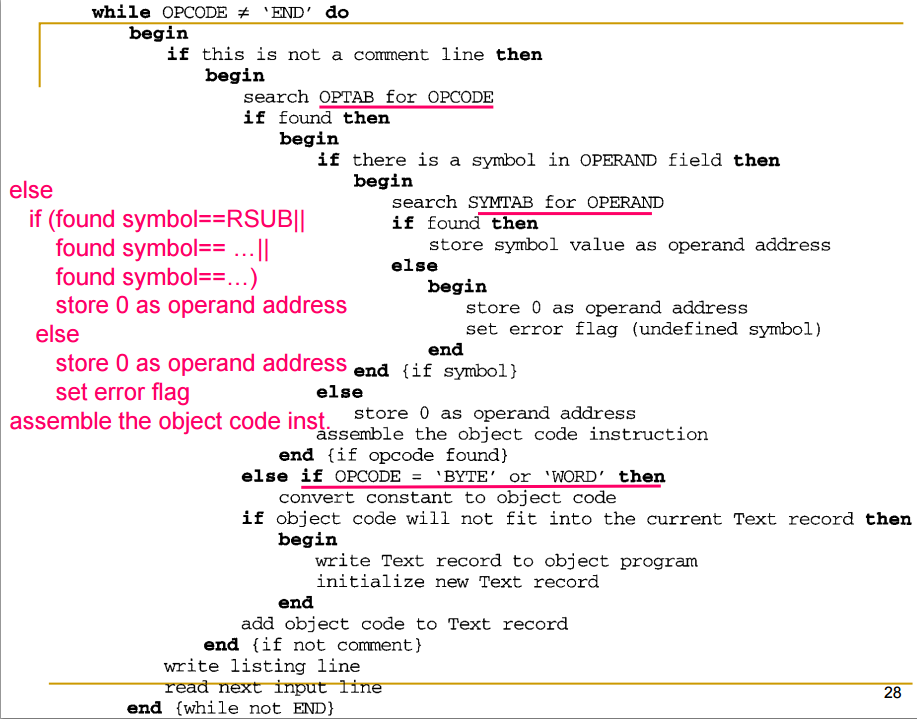
박스에서 해당 text record의 object code를 넣어준다.
end directive를 만날때까지 iteration
opcode field의 값을 확인한다.
현재 statement가 instruction인지, directive인지 확인한다.
instruction이면 이에 대한 object code를 만들어야 한다.
먼저 operand code에 symbol이 있는지 확인한다
있다면 symbol table을 확인하고 symbol이 있다면 address value를 operand address로써 저장을 해둔다. object code를 만들때 사용을 한다. 만약 못찾았다면 error flag를 setting한다.
없다는 것은 operand value를 사용하지 않는다는 것이므로 0으로 저장한다. error case가 아니라 sic/xe의 경우 format 1이 operand 값을 가지지 않고 동작함을 기억한다. 0값을 넣어준다.
opcode로 바꿔주고 operand address로 (?) "assemble the object code instruction" 적절한 형태로 만든다.
만약 inputline이 byte나 word에 대한 directive면 const값을 char을 ascii로 바꾼다던지 integer로 하던지..
object code를 최종적으로 text code에 넣고 싶다. 공간이 있는지 없는지. 담지 못하면 text record를 object program에 써주고 새로 text record에 넣어준다. 다음으로 list line을 쓰고 일긍면서 확인한다.
end directive를 만나면 나머지를 확인한다.
write last Text record to object program
write End record to object program
write last listing line
그림 2.2 2.3 파일들이 만들어진다.
