Overview
System SW and Its Machine Dependency
- The design of system software is greatly influenced by the architecture of the machine(= computer) on which it runs.
- For example, assemblers translate mnemonic instruction into machine code, and OS directly manages the resources of a computing system
- Specific implementations of systems change over time, but the underlying concepts do not.
- The basic structure and design of system software is essentially the same for most computers.
- For instance, general design and logic of assemblers are almost same for any machine architecture.
- 시스템 소프트웨어의 설계는 그것이 실행되는 기계(= 컴퓨터)의 아키텍처에 의해 크게 영향을 받는다.
- 예를 들어, 어셈블러는 mnemonic instruction을 machine code로 변환하고 OS는 컴퓨팅 시스템의 리소스를 직접 관리한다.
- 시스템의 구체적인 구현은 시간이 지남에 따라 변하지만 기본 개념은 변하지 않는다.
- 시스템 소프트웨어의 기본 구조와 디자인은 대부분의 컴퓨터에서 기본적으로 동일하다.
- 예를 들어, 어셈블러의 일반적인 설계와 논리는 모든 기계 아키텍처에서 거의 동일하다.
Computer Organization and Design: A Reminder
5 classic components of a computer
: input, output, memory, datapath, and control, with the last two sometimes combined and called the processor
: 입력, 출력, 메모리, 데이터 경로 및 제어. 마지막 두 가지가 때때로 조합되어 프로세서로 호출된다.
input, output, memory, datapath, control
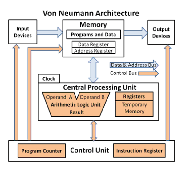
Computer(= Machine) Architecture
• Structure of a simple computer
input, memroy, output
cpu
control unit
Memory Unit, CPU, Control Unit
- Memory unit contains both programs (= a sequence of instructions) and data
- CPU runs the program by executing instructions via ALU
- ALU performs mathematical and logical operations
- Control unit organizes the actions of CPU, and sequences the actions of the other components to execute programs
-> “Fetch-Decode-Execute” cycle
- Memory unit에는 프로그램(= 일련의 명령)과 데이터가 모두 포함되어 있다.
- CPU는 ALU를 통해 명령을 실행하여 프로그램을 실행한다.
- ALU는 수학적 및 논리적 연산을 수행한다.
- Control unit(제어 장치)는 CPU의 동작을 정리하고 다른 구성 요소의 동작을 순서화하여 프로그램을 실행한다.
-> "Fetch-Decode-Execute" 사이클
Memory unit에는 프로그램과 데이터가 모두 포함
CPU는 ALU를 통해 명령 실행, 프로그램 실행
control unit (제어장치)는 동작을 순서화하여 프로그램 실행 (Fetch-Decode-Execute)
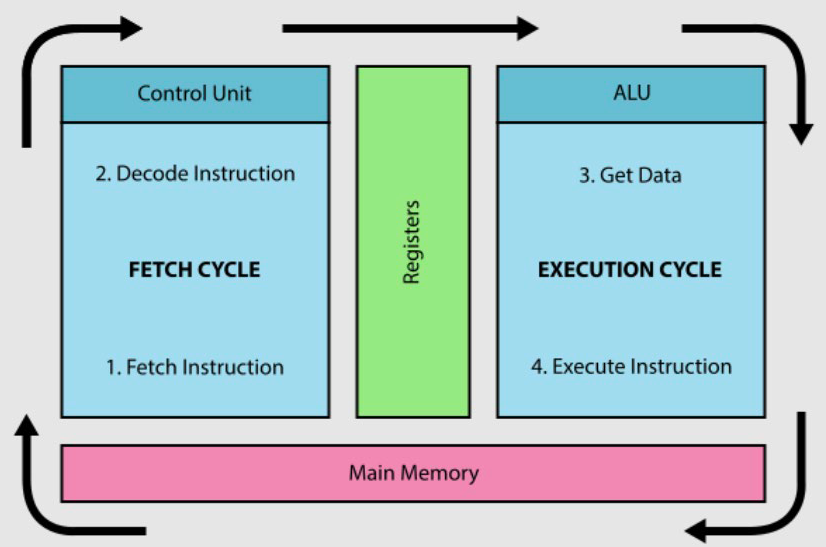
The Fetch-Decode-Execute Cycle
• The following 3 steps are repeated over and over againuntil we reach the last instruction of a program (usually HALT, STOP or QUIT)
– Fetch from memory the next instruction to be executed
– Decode it (= Determine what should be done)
– Execute it by issuing the appropriate command to the ALU, memory, and I/O Controllers
• 다음 3단계는 프로그램의 마지막 지침에 도달할 때까지 반복된다(일반적으로 HALT, STOP 또는 QUIT).
– 메모리에서 실행할 다음 명령 가져오기 (Fetch)
– 디코딩(= 수행할 작업 결정) (Decode)
– ALU, 메모리 및 I/O 컨트롤러에 적절한 명령을 실행하여 실행 (Execute)
Fetch: 명령 가져오기
Decode: 수행할 작업 결정
Execute: 실행
SIC (Simplified Instructional Computer)
- A hypothetical computer that includes the h/w features most often found on real machines, while avoiding unusual or irrelevant complexities.
- Separated from any specific implementation details, in order to understand the basic conceptsof a piece of system software.
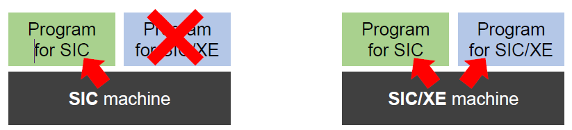
- Two versions with upward compatibility
- SIC: the standard model
- SIC/XE: the eXtraEquipment (or Expensive) model
- Programs for SIC can be executed on SIC/XE machine
- 실제 컴퓨터에서 가장 자주 볼 수 있는 h/w 기능을 포함하는 hypothetical computer는 특이하거나 관련이 없는 복잡성을 피한다.
- 시스템 소프트웨어의 기본 개념을 이해하기 위해, 특정 구현 세부 사항과 분리된다.
- 두 가지 버전과 상향 호환성
- SIC: 표준 모델
- SIC/XE: eXtra장비(또는 고가) 모델
- SIC용 프로그램은 SIC/XE 시스템에서 실행할 수 있다.
hypothetical computer는 특이하거나 관련이 없는 복잡성을 피한다.
upward compatibility
SIC Machine Architecture
Memory
Memory in General
- Memory is just a large, single-dimensional array, with the address acting as the index to that array, starting at 0
- It is divided into fixed-sized units called cells. Each cell is associated with a unique identifier called an address.
- Any location in the memory can be accessed very fast just by specifying the address of the location
- Programs (and data) are stored in main memory when they are running
- RAM is linked to CPU in such a way that data can be moved from one to the other very quickly
- Memory(메모리)는 단지 0부터 시작하여 주소가 해당 배열의 인덱스로 작용하는 대규모 단일 차원 배열이다.
- 그것은 cells(셀)이라고 불리는 고정된 크기의 단위로 나뉜다. 각 셀은 address(주소)라고 불리는 고유 식별자와 연관된다.
- 위치 주소를 지정하기만 하면 메모리의 모든 위치에 매우 빠르게 액세스할 수 있다.
- 프로그램(및 데이터)은 실행 중일 때 기본 메모리에 저장된다.
- RAM은 데이터를 매우 빠르게 이동할 수 있는 방식으로 CPU에 연결된다.
메모리 : 대규모 단일 차원 배열
cell이라는 고정된 크기 단위 / address 고유 식별자
위치 주소 지정
프로그램은 기본 메모리에 저장
RAM은 빠르게 이동할 수 있는 방식으로 CPU에 연결
Memory in SIC
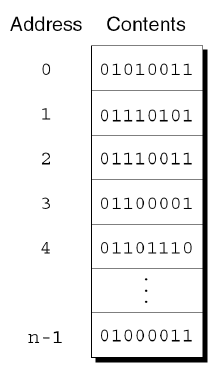
- Consists of 8-bit bytes; 3-byte words (i.e., 24bits);
- Maximum memory available: 32 KB (2^15 bytes)
- 8비트 바이트, 3바이트 워드(24비트)로 구성된다.
- 사용 가능한 최대 메모리: 32KB(2^15바이트)
SIC: 8-bit bytes; 3-byte words(24bits) / 최대 메모리(32kb = 2^15byte)
24bits - 정수와 명령 표현
Register
Registers in General
- Individual high-speed storage locations, internal to the CPU, used to hold transient data.
- Some are dedicated for particular purposes,others are used as temporary stores during computations
- 임시 데이터를 저장하는 데 사용되는 CPU 내부의 개별 고속 저장 위치이다.
- 일부는 특정 목적을 위해 전용되고, 다른 일부는 계산 중에 임시 저장소로 사용된다.
register: 임시 데이터 저장, CPU 내부 개별 고속 저장 위치
일부 특정 목적, 일부 계산 임시 저장소
Registers in SIC -- 5 Special purposed registers (24 bits)
- A (0): Accumulator. For basic arithmetic operations.
- X (1): Index register. For storing an index value for addressing.
- L (2): Linkage register. For storing/jumping to specific memory addresses
- PC (8): Program Counter. For storing the address of the next instruction to run.
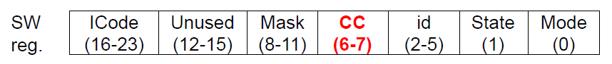
- SW (9): Status Word. For storing a variety of information, such as CC (condition code) bits used for comparisonand conditional jumpinstructions
- A (0): Accumulator. 기본 산술 연산에 사용된다.
- X (1): Index register. 주소 지정을 위한 인덱스 값을 저장한다.
- L (2): Linkage register. 특정 메모리 주소로 저장/점프하기 위해.
- PC (8): Program Counter. 실행할 다음 명령의 주소를 저장한다.
- SW (9): Status Word. 비교 및 조건부 점프 명령에 사용되는 CC(조건 코드) 비트 등 다양한 정보 저장용.
A(0): Accumulator. 기본 산술 연산
X(1): Index register. 인덱스
L(2): Linkage register. 특정 메모리 주소로 저장/점프
PC(8): Program Counter: 다음 명령어 주소
SW(9): Status Word. CC 등 다양한 정보 저장
Data Formats
Data Formats
- Integers are stored as 24-bit binary numbers
- 2’s complement representation is used for negative values
- Characters are stored using 8-bit ASCII codes
- No floating-point hardware
- 정수는 24비트 이진수로 저장된다.
- 2의 보완 표현은 음수 값에 사용된다.
- 문자는 8비트 ASCII 코드를 사용하여 저장된다.
- 부동소수점 하드웨어 없음
정수 24-bit binary numbers - 음수 값 2's complement
문자 8-bit ASCII codes
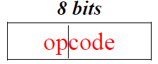
Machine Instruction Formats
- All instructions on the standard version of SIC have 24-bit format
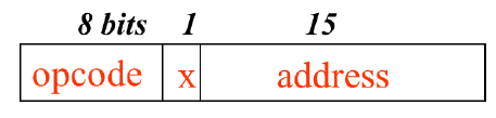
- Operation code field (= op code): A unique number assigned to each machine language operation recognized by the hardware (see Appendix A)
- Address field: Memory addresses of the values on which the operation will work
- SIC의 표준 버전에 대한 모든 명령은 24비트 형식이다.
- Operation code field(=opcode): 하드웨어가 인식하는 각 기계어 작업에 할당된 고유 번호이다.(Appendix A 참조)
- Address field: 작업이 작동할 값의 메모리 주소
SIC 표준 버전 명령 24-bit (정수와 같음)
Address Mode
Addressing Modes in General
-
It specifies how to calculate the effective(= target) memory address of an operand by using information held in registers and/or constants contained within a machine instruction (by Wikipedia)
-
기계 명령어에 포함된 레지스터 및/또는 상수에 저장된 정보를 사용하여 피연산자의 유효(= 목표) 메모리 주소를 계산하는 방법을 지정한다.
operand의 effective(=target) memory address 계산
Addressing Modes in SIC
- There are two addressing modes available, indicated by the setting of the x bit in the instruction
- Direct addressing mode, when the flag bit, x = 0:
» Target Address = address - Indexed addressing mode, when the flag bit x = 1:
» Target Address = address + (X)
X-> The value of register X(not the ‘x’ bit of the instruction)
- Direct addressing mode, when the flag bit, x = 0:
- instruction의 x 비트 설정에 따라 두 가지 주소 지정 모드를 사용할 수 있다.
- 직접 주소 지정 모드, 플래그 비트가 x = 0 일 때
» 대상 주소 = 주소 - 인덱싱된 주소 지정 모드, 플래그 비트 x = 1 일 때
» 대상 주소 = 주소 + (X)
X-> 레지스터 X의 값(명령어의 'x' 비트가 아님)
- 직접 주소 지정 모드, 플래그 비트가 x = 0 일 때
x 비트에 따라 주소 지정 모드 사용
Direct addressing mode: x=0
Indexed addressing mode: x=1
Instruction Set (in General)
- The complete set of all the instructions in machine code that can be recognized and executed by a CPU
- It provides commands to the processor to tell what it needs to do.
- It defines addressing modes, instructions, native data types, registers, memory architecture, interrupt, exception handling, and external I/O
- Also, called as “ISA(Instruction Set Architecture)”
- CPU가 인식하고 실행할 수 있는 기계 코드로 된 모든 명령의 완전한 집합
- 프로세서에 필요한 작업을 지시하는 명령을 제공한다.
- 주소 지정 모드, 명령, 네이티브 데이터 유형, 레지스터, 메모리 아키텍처, 인터럽트, 예외 처리 및 외부 I/O를 정의한다.
- 또한 "ISA(Instruction Set Architecture)"라고도 한다.
명령어 집합
ISA
A basic set of instructions provided by SIC
Load or Store instructions: LDA, LDX, STA, STX, etc.
- LDA m? A<-(m..m+2), where A and mindicate register A and a memory address, respectively; It specifies that the contents of the memory locations mthrough m+2are loaded into register A
- STA m? m..m+2<-(A); It specifies that the contents of register A are stored in the word that begins at address m
- LDA m? A<-(m..m+2), A와 mindicate register A와 메모리 주소, 메모리 위치 m ~ m+2의 내용이 레지스터 A에 로드되도록 지정한다.
- STA m? m..m+2<-(A); 레지스터 A의 내용이 주소 m으로 시작하는 word에 저장되도록 지정한다.
LDA: load, m~m+2 내용 load
STA: store, m으로 시작하는 word에 저장
Integer Arithmetic operations: ADD, SUB, MUL, DIV
- All arithmetic operations involve register A and a word in memory, with the result being left in the register
- 모든 산술 연산은 레지스터 A와 메모리에 있는 word를 포함하며, 결과는 레지스터에 남는다.
- » ADD m? A <- (A) + (m..m+2)
» SUB m? A <- (A) -(m..m+2)
» MUL m? A <- (A) * (m..m+2)
» DIV m? A <- (A) / (m..m+2)
A와 memory의 word 포함. 결과는 register에 남음.
ADD, SUB, MUL, DIV
Comparison: COMP
-
COMP m? (A) : (m..m+2), meaning that it compares the value in register A with a word in memory, and sets a condition code (CC) of register SW to indicate the result
» <->01 bits, =->00bits, or >->10 bits -
COMP m? (A) : (m..m+2), 이것은 레지스터 A의 값을 메모리에 있는 word와 비교하고 레지스터 SW의 조건 코드(CC)를 설정하여 결과를 나타낸다.
» <->01 bits, =->00bits, or >->10 bits
COMP: register A 값을 memory의 word와 비교해서 레지스터 SW의 CC를 설정하여 결과 나타냄
<: 01bits, =:00bits, >:10bits
Conditional Jump: JLT, JEQ, JGT
- These instructions test the setting of CC, and jump accordingly
- 이 instruction은 CC 설정을 테스트하고 그에 따라 점프한다.
- JLT m? PC <- m if CC set to <
- JEQ m? PC <- m if CC set to =
- JGT m? PC <- m if CC set to >
JLT, JEQ, JGT: CC 설정 test
Subroutine linkage: JSUB, RSUB
- JSUB m? L <- (PC); PC <- m
» JSUB jumps to the subroutine, placing the return address in register L - RSUB? PC <- (L)
» RSUB returns by jumping to the address contained in register L
- JSUB m? L <- (PC); PC <- m
» JSUB는 서브루틴으로 점프하여 반환 주소를 레지스터 L에 배치한다. - RSUB? PC <- (L)
» RSUB는 레지스터 L에 포함된 주소로 점프하여 반환한다.
JSUB: 서브루틴 점프하여 반환 주소를 L에 배치
RSUB: L에 포함된 주소로 점프하여 반환
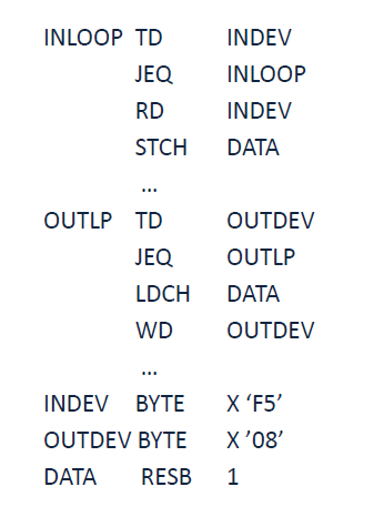
I/O (Input and Output)
- Performed by transferring 1 byte at a time to or from the rightmost 8 bits of register A
- Each device is assigned a unique 8-bit code
- 3 instructions: TD (test device), RD (read data) , WD (write data)
» TD m? meaning that it tests if the device specified by (m) is ready to send or receive a byte of data - If the device is ready, CC of register SW is set to “<”
- If not, CC is set to “=”
» RD m? A [rightmost byte] <- data from the device specified by (m)
» WD m? the device specified by (m) <- A[rightmost byte]
- 레지스터 A의 맨 오른쪽 8비트 사이에서 한 번에 1바이트씩 전송하여 수행한다.
- 각 장치에는 고유한 8비트 코드가 할당된다.
- 3가지 instruction: TD(테스트 장치), RD(데이터 읽기), WD(데이터 쓰기)
» TD m? 즉, (m)에서 지정한 장치가 데이터 바이트를 전송하거나 수신할 준비가 되었는지 테스트한다. - 장치가 준비되면 레지스터 SW의 CC가 "<"로 설정된다.
- 그렇지 않으면 CC가 "="로 설정된다.
» RD m? A [최우측 바이트] <- (m)으로 지정된 장치의 데이터
» WD m? (m)으로 지정된 장치 <- A [최우측 바이트]
I/O Input and Output
register A의 rightmost 8 bits 사이에서 한 번에 1byte씩 전송하여 수행
각 장치에는 고유한 8-bit 코드가 할당
TD, RD, WD
TD: 준비 테스트 / 준비되면 SW의 CC가 <, 준비되지 않았다면 CC가 =
RD: 데이터 읽기, A rightmost byte
WD: 데이터 쓰기, A rightmost byte
SIC/XE Architecture
Memory
- Maximum memory available: 1 MB (2^20 bytes)
- 사용 가능한 최대 메모리: 1MB(2^20바이트)
사용 가능 최대 메모리 : 1MB (2^20 bytes)
Registers
- 5 registers as SIC + 4 additional ones (B, S, T and F)
- B (3): Base register –used for addressing (24bits)
- S (4) and T (5): General working register –no special use (24bits)
- F (6): Floating-point accumulator (48 bits)
- SIC의 5 registers + 추가 레지스터 4개 (B, S, T 및 F)
- B (3): 기본 레지스터 – addressing(24비트)에 사용
- S (4) 및 T (5) : 일반 작업 레지스터 – 특별한 사용 없음 (24비트)
- F (6): 부동소수점 계산기 (48비트)
SIC의 5 register (A,X,L,PC,SW) + (B,S,T,F)
B(3): 기본 레지스터 - addressing(24bits)에 사용
S(4), T(5): 일반 작업 레지스터, 사용 없음 (24bits)
F(6): 부동소수점 계산기 (48bit)
Data Formats
- The same data formats as the standard version
- 48-bit floating-point data type, in addition
- 표준 버전과 동일한 데이터 형식
- 48비트 부동소수점 데이터 유형, 추가
48bit 부동소수점 data type 추가
double size of integer number (24bit)
정수의 두 배 크기(24비트)
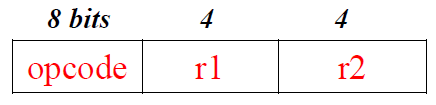
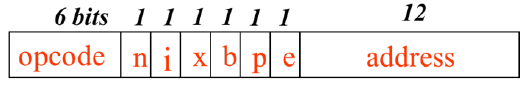
(Machine) Instruction Formats
- Format 1: No memory reference (1 byte)
- 형식 1: 메모리 참조 없음(1바이트)
- Format 2: No memory reference (2 bytes), for register operations
- 형식 2: 레지스터 작업에 대한 메모리 참조 없음(2바이트)
메모리 참조가 없다 = 연산은 할 수 있는데 register 간의 연산이다.
기본적으로 포맷 4개가 제공된다.
format 1,2는 memory reference가 없다. operand가 없거나 register operations를 사용한다.
- Format 3: Relative addressing (3 bytes)
- 형식 3: 상대 주소 지정(3바이트)
- Flag e = 0
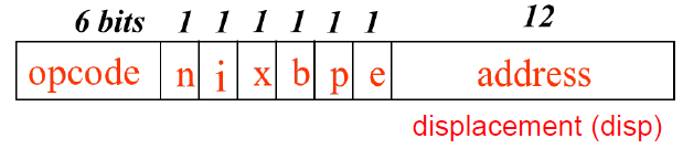
상대 주소 지정 (3byte), Flag e = 0
format 3는 relative addressing, 11bits라서 전체를 다 표현하지 못한다
- Format 4: Address field extension to 20 bits (4 bytes)
- 형식 4: 주소 필드를 20비트(4바이트)로 확장
- Flag e = 1
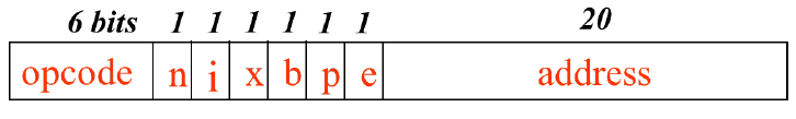
주소 확장. Flag e =1
format4는 address filed extension
memory filed가 1btye라 어떤 공간이든 나타낼 수 있다.
Addressing Modes
정리(nixbpe)
n,i : immediate addressing(n=0,i=1/n=0,i=), indirect address(n=1,i=0) 결정
x : index addressing (x=1)
b,p : relative addressing(b=1,p=0/b=0,p=1), direct addressing(b=0,p=0), (b=1,p=1 불가능) 결정 (어떻게 target address를 조회할 수 있는지)
e : format 3(Flag e=0), format 4 (Flag e=1) 결정
b,p
- Relative addressing modes for Format 3
- Base relative addressing, when b=1, p=0: TA= (B) + disp/addr
- PC relative addressing, when b=0, p=1: TA= (PC) + disp/addr
- Direct addressing mode for Format 3 & 4 (~-=)
- b = p = 0: TA = disp/addr
- cf., b = p = 1 is impossible (it’s error case!)
- b = p = 0: TA = disp/addr
- These addressing modes can be combined with indexed addressing, when x=1, the term (X) is added in the target address calculation
- index addressing = base register value + dis/addr value + x address value
- Relative addressing 형식 3의 모드
- Base relative addressing, b=1, p=0일 때: TA= (B) + disp/addr
- PC relative addressing, b=0일 때 p=1: TA=(PC) + disp/addr
- Direct addressing 형식 3 및 4의 모드(~-=)
- b = p = 0: TA = disp/addr
- cf., b = p = 1은 불가능하다 (오류 사례다!)
- b = p = 0: TA = disp/addr
- 이러한 주소 지정 모드는 indexed addressing과 결합할 수 있으며, x=1일 때 목표 주소 계산에 (X)라는 용어가 추가된다.
- index addressing = 기본 레지스터 값 + dis/addr 값 + x address 값
Base relative addressing: b=1,p=0, TA=B+disp/addr
PC relative addressing: b=0,p=1,TA=PC+disp/addr
direct addressing: b=0,p=0
(b=p=1 불가능)
n,i
- n and i bits in Format 3 and 4 are used to specify how the target address is used.
- n=0, i=1: immediate addressing, no memory reference, target address is used as operand value
- n=1, i=0 : indirect addressing
- i=0, n=0: simple addressing for SIC.
- It means that b, p, and e are used as address fields (for upward compatible)
- i=1, n=1: simple addressing for SIC/XE
- Indexing cannot be used with immediate or indirect addressing mode.
- n 및 i비트는 대상 주소의 사용 방법을 지정하는 데 사용된다.
- n=0, i=1: immediate addressing, 메모리 참조 없음, 대상 주소가 피연산자 값으로 사용됨
- n=1, i=0: indirect addressing
- i=0, n=0: 단순 주소 지정 for SIC.
- 이는 b, p, e가 상향 호환을 위해 주소 필드로 사용된다는 것을 의미한다.
- i=1, n=1: SIC/XE에 대한 단순 주소 지정
- 즉시 또는 간접 주소 지정 모드에서는 인덱싱을 사용할 수 없다.
immediate addressing: n=0,i=1
don't need access memory to find operand value
TA가 주소값이 아니라 operand의 value 자체이다.
indirect addressing: n=1, i=0
should access memory at least two times.
TA가 주소값이다.
inderect address는 또 다른 address value로 접근해야 진짜 address value를 찾을 수 있다.
simple addressing : i=0,n=0. 단순 주소 지정. b,p,e가 주소 필드로 사용
b,p,e,address (address) -> address fields
opcode, n=0, i=0 (operation) -> opcode00
immediate, indirect mode에서는 인덱싱을 사용할 수 없다.
Example
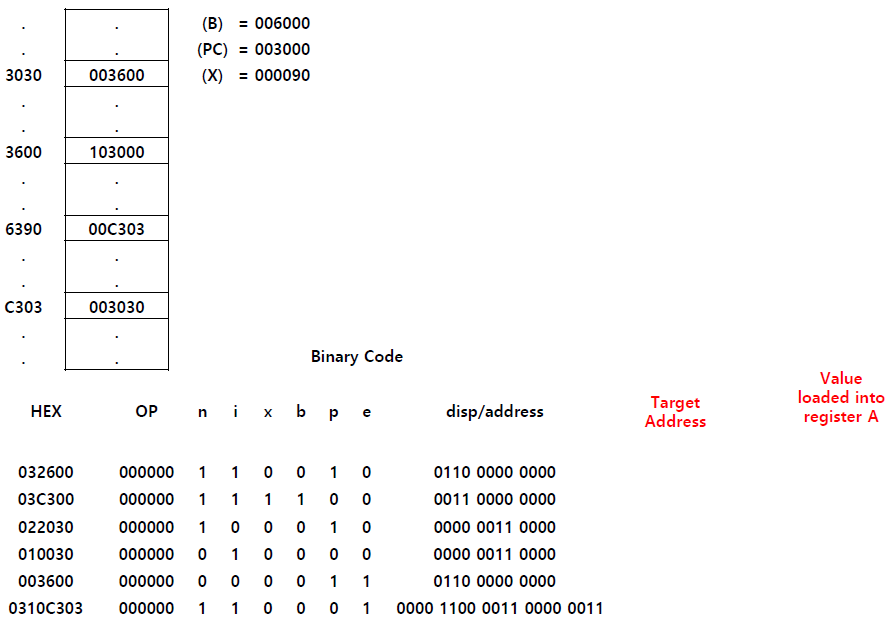
풀어보기
Instruction Set
- All instructions on standard version
- Load and Store registers: LDB, STB, etc.
- Floating-point arithmetic operations: ADDF, SUBF, MULF, DIVF
- ADDF m? F <- (F) + (m..m+5)
- Register-to-register instructions: RMO, ADDR, SUBR, MULR, DIVR
- RMO r1, r2 ? r2 <- (r1)
- ADDR r1, r2 ? r2 <- (r2) + (r1)
- Supervisor call: SVC
- SVC n
» Generate SVC interrupt for communication with OS
» n is a supervisor call number (i.e., interrupt number)
- SVC n
- 표준 버전에 대한 모든 instructions
- Load 및 Store 레지스터: LDB, STB 등
- 부동소수점 연산: ADDF, SUBF, MULF, DIVF
- ADDF m? F <- (F) + (m..m+5)
- Register-to-register instructions: RMO, ADDR, SUBR, MULR, DIVR
- RMO m1, r2 ? r2 <- (r1)
- ADDR r1, r2 ? r2 <- (r2) + (r1)
- Supervisor call: SVC
- SVC n
» OS와의 통신을 위한 SVC 인터럽트 생성
» n은 슈퍼바이저 호출 번호(즉, 인터럽트 번호)입니다.
- SVC n
instruction set
1) Load and Store
2) Floating-point arithmetic operations
3) Register-to-register instructions
4) Supervisor call : SVC n / OS와의 통신, interrupt 번호가 n
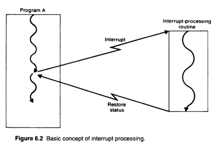
important: operating system part, not program part
Input and Output
- The I/O instructions for SIC are also available on SIC/XE
- In addition, there are I/O channels that can be used to perform input and output, while the CPU is executing other instructions
- I/O channels -> simple processors for executing I/O operations instead of CPU
- This allows overlap of computing and I/O, resulting in more efficient system operation
- SIO (start), TIO (test), HIO (halt)
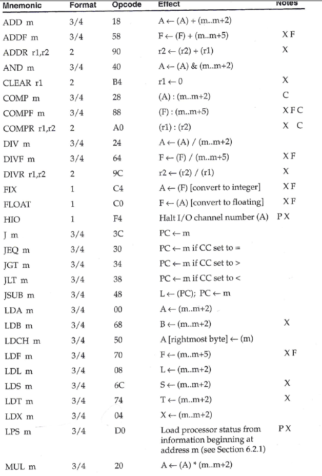
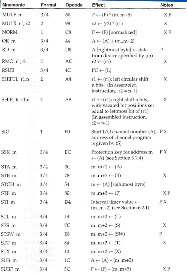
- Appendix A gives a complete list of all SIC and SIC/XE instructions, with their operation codes and a specification of the function performed by each!
- SIC에 대한 I/O 지침은 SIC/XE에서도 사용할 수 있다.
- 또한 CPU가 다른 명령을 실행하는 동안 입출력을 수행하는 데 사용할 수 있는 I/O 채널도 있다.
- I/O 채널 -> CPU 대신 I/O 작업을 실행하기 위한 간단한 프로세서
- 이를 통해 컴퓨팅과 I/O가 중복되어 보다 효율적인 시스템 운영이 가능하다.
- SIO(시작), TIO(테스트), HIO(정지)
- 부록 A는 모든 SIC 및 SIC/XE 명령의 전체 목록과 작동 코드 및 각 명령이 수행하는 기능의 사양을 제공한다.
I/O channel : CPU 대신 I/O 작업 실행하는 간단한 프로세서
Assembly
Assembly Language Statements
- 3 types of functional statements:
- Instructions: translated by the assembler into one or more bytes of object code, which will be executed at runtime.
- Each instruction corresponds to one of the operations.
- Directives: tells the assembler to take some action.
- No effect on the object code
» e.g., WORD directive generates one-word integer constant.
- No effect on the object code
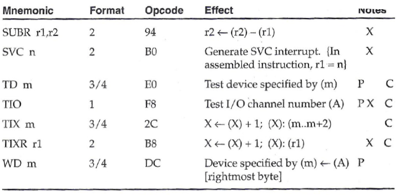
- Macro: “shorthand” for a sequence of other statements.
- The assembler expands a macro to the statements it represents, and then assembles these new statements.
- Instructions: translated by the assembler into one or more bytes of object code, which will be executed at runtime.
- 3가지 유형의 기능 설명:
- Instructions: 어셈블러가 런타임에 실행되는 object code의 하나 이상의 바이트로 변환합니다.
- 각 명령은 작업 중 하나에 해당한다.
- Directives: 어셈블러에게 조치를 취하도록 지시합니다.
- object code에 영향을 미치지 않는다.
» 예를 들어, WORD 지시어는 하나의 단어 정수 상수를 생성한다.
- object code에 영향을 미치지 않는다.
- Macro: 다른 문의 시퀀스에 대한 "단축"이다.
- 어셈블러는 매크로를 나타내는 statements으로 확장한 다음 이러한 새 statement을 어셈블한다.
- Instructions: 어셈블러가 런타임에 실행되는 object code의 하나 이상의 바이트로 변환합니다.
Instruction: object code의 하나 이상의 byte로 변환
directives: 어셈블러에게 조치를 취하도록 지시. object code에 영향을 미치지 않는다.
Macro: other statements에 대한 단축이다.
Examples
SIC Programming Examples
- [pp. 12-20] Simple examples of SIC and SIC/XE assembler language programming
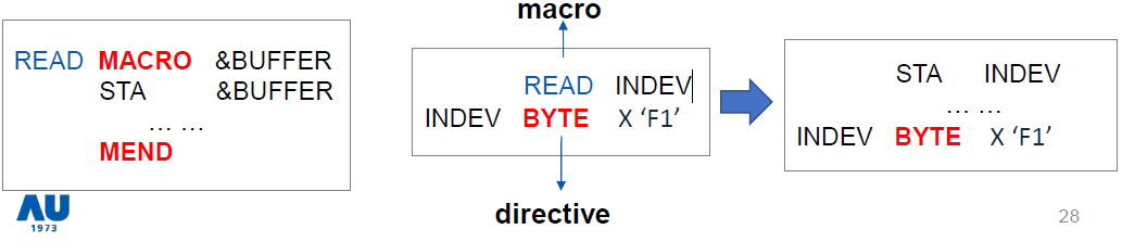
- Figure 1.2: Data movement operations
- No memory-to-memory move instructions
- Figure 1.3: Arithmetic instructions
- All operations are performed using register A
- Figure 1.4 and 1.5: Looping and indexingoperations
- Figure 1.6: I/O operations
- Figure 1.7: Subroutine call & record input operations
- Figure 1.2: Data movement operations
self study required
Figure 1.2
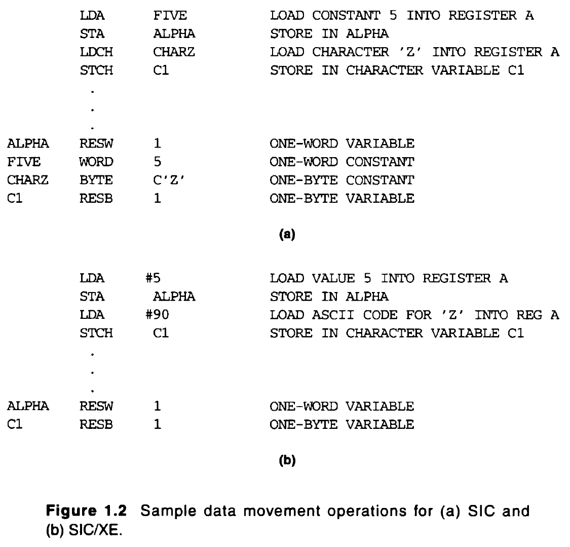
Figure 1.2 (a),(b)
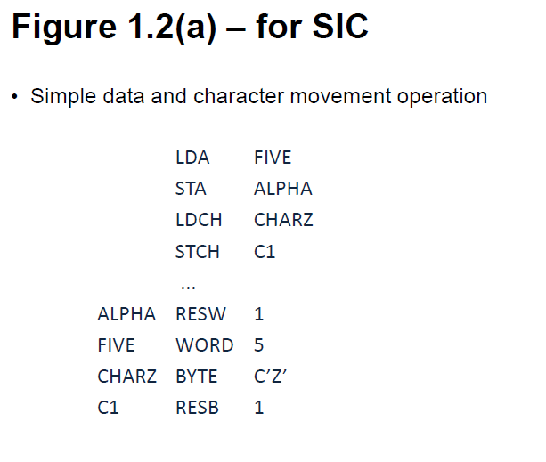
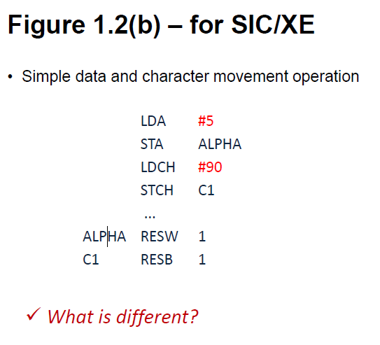
What is different? immediate address mode. you can see # symbol. this instruction corresponding to this instr.
Figure 1.3 (a)
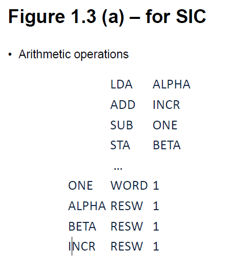
Figure 1.4 (a)
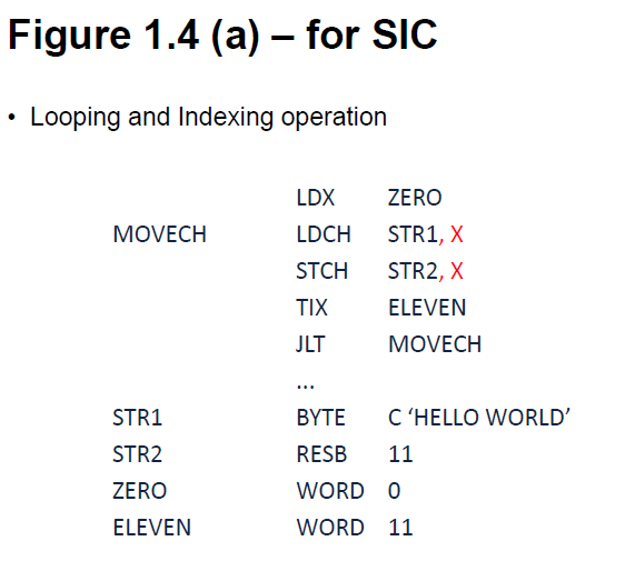
Figure 1.6
Architecture
Actual Machine Architecture
CISC(Complex Instruction Set Computers - 복합 명령어 집합 컴퓨터)
- Large and complicated instruction sets provided
- Several different instruction formats and length
- Many different addressing modes
- Implementation in h/w tends to be complex
- 대규모 및 복잡한 명령어 집합을 제공
- 다양한 명령 형식 및 길이
- 다양한 주소 지정 모드
- h/w에서의 구현은 복잡한 경향이 있음
CISC: Lage and complicated instruction sets
다양한 명령 형식, 길이 / 주소 지정 / 구현 복잡
RISC(Reduced Instruction Set Computers - 저감 명령 집합 컴퓨터)
- Small number of machine instructions, instruction formats, and addressing modes
- A standard, fixed instruction length, and single-cycle execution
- Advantages:
- simplify the design of processors
- faster and less expensive processor development
- greater reliability, faster instruction execution times
- 소수의 기계 명령, 명령 형식 및 주소 지정 모드
- 표준, 고정 명령 길이 및 단일 주기 실행
- 장점:
- 프로세서의 설계를 단순화
- 보다 빠르고 저렴한 프로세서 개발
- 안정성 향상, 명령 실행 시간 단축
RISC: Small number of machine instructions, instruction formats, and addressing modes
프로세서 설계 단순화, 빠르고 저렴 안정성 향상
ARM Architecture
- Acorn RISC Machine (later, Advanced RISC Machine)
- ARM Core
- Cortex A, M series (e.g.M4)
- ARM Assembler
- Acorn RISC Machine(이후, 발전된 RISC Machine)
- ARM 코어
- Cortex A, M 시리즈(예:M4)
- ARM 조립기
ARM은 Acron RISC Machine