목표
chosen노드가 무엇인지 이해하고, 왜 필요한지 설명할 수 있다.- Zephyr가 사용하는 기본 I/O 장치 (
console,stdout,entropy등)의 연결 방식을 이해한다. - 실제 DTS 구조를 따라가며
zephyr,chosen을 분석하고 override하는 실습을 해본다.
1. chosen노드란?
chosen노드는 zephyr가 시스템에서 사용할 특정 장치를 빠르게 찾을 수 있도록 지정하는 중앙 참조 포인터 역할을 함.(chosennode는skeleton.dtsi에 define 되어있음.)- 즉, 커널이 필요한 주변장치와 HW정보는
chosennode로 묶어서 커널 이식성을 키우는 효과를 냄.
2. zephyr.dts에서 chosen 노드 찾아보기
// zephyr.dts
/ {
	/* node '/chosen' defined in zephyr/dts/common/skeleton.dtsi:12 */
	chosen {
		zephyr,bt-hci = &bt_hci_controller;
		zephyr,entropy = &rng;
		zephyr,flash-controller = &flash_controller;
		zephyr,sram = &sram0;
		zephyr,flash = &flash0;
		zephyr,code-partition = &slot0_partition;
		zephyr,console = &uart0;
		zephyr,shell-uart = &uart0;
		zephyr,uart-mcumgr = &uart0;
		zephyr,bt-mon-uart = &uart0;
		zephyr,bt-c2h-uart = &uart0;
		zephyr,ieee802154 = &ieee802154;
		zephyr,boot-mode = &boot_mode0;
	};
zephyr.dts는 빌드시스템이 타겟 보드의 HW 정보를 담은 devicetree파일(.dts,.dtsi)을 모두 묶어서, 하나의.dts파일로 만든것을 의미. 즉, 해당 보드의chosennode정보를 한번에 볼 수 있다.(실제 빌드에 사용되는 요소가 묶여있으니, 디버깅시 가장 정확하게 참고할 수 있음.)
nrf52840dk chosen의 주요 요소
zephyr,console = &uart0: 사용자printf,logging에 사용되는 node정보를 담음.
uart0: uart@40002000 {
	reg = < 0x40002000 0x1000 >;
	interrupts = < 0x2 0x1 >;
	compatible = "nordic,nrf-uarte";
	status = "okay";
	current-speed = < 0x1c200 >;
	pinctrl-0 = < &uart0_default >;
	pinctrl-1 = < &uart0_sleep >;
	pinctrl-names = "default",
					"sleep";
};
zephyr,shell-uart = &uart0: 사용자 shell 입력에 사용되는 HW node를 담음(zephyr,console과 마찬가지로&uart0를 사용)zephyr,entropy = &rng: Zephyr의entropy는 보안용 키, UUID, BLE 주소 등 난수(random number)가 필요한 곳에서 하드웨어 RNG를 통해 무작위 값을 얻기 위해 사용됨.(nrf의 난수생성기를 사용하며, 노이즈 기반의 HW난수를 생성.)
rng: random@4000d000 {
	compatible = "nordic,nrf-rng"; /* in zephyr/dts/arm/nordic/nrf52840.dtsi:277 */
	reg = < 0x4000d000 0x1000 >;   /* in zephyr/dts/arm/nordic/nrf52840.dtsi:278 */
	interrupts = < 0xd 0x1 >;      /* in zephyr/dts/arm/nordic/nrf52840.dtsi:279 */
	status = "okay";               /* in zephyr/dts/arm/nordic/nrf52840.dtsi:280 */
};
zephyr,flash = &flash0: 커널이 flash 메모리에 접근하기위한 노드정보,flash0는 각 파티션 정보를 담고있음.(OTA를 고려한 파티션구조이며, 메모리가 OTA를 위해 설계된게 아닌, 논리적으로 구분해둔것일 뿐.)
-mcuboot: 부트로더, 기기 부팅 시 가장 먼저 실행됨.
-image-0: 메인 펌웨어. 실제로 실행될 어플리케이션 이미지
-image-1: 업데이트용 이미지 저장 공간. OTA시 여기 다운로드됨.
-storage: NVS(Non-Volatile Storate) or 설정 저장 공간.
flash0: flash@0 {
	compatible = "soc-nv-flash";
	erase-block-size = < 0x1000 >;
	write-block-size = < 0x4 >;
	reg = < 0x0 0x100000 >;

	partitions {
		compatible = "fixed-partitions";
		#address-cells = < 0x1 >;
		#size-cells = < 0x1 >;

		boot_partition: partition@0 {
			label = "mcuboot";
			reg = < 0x0 0xc000 >;
		};

		slot0_partition: partition@c000 {
			label = "image-0";
			reg = < 0xc000 0x76000 >;
		};

		slot1_partition: partition@82000 {
			label = "image-1";
			reg = < 0x82000 0x76000 >;
		};

		storage_partition: partition@f8000 {
			label = "storage";
			reg = < 0xf8000 0x8000 >;
		};
	};
};
};
3. 실습: zephyr,console-uart를 변경해보기.
현재 shell-uart와 zephyr,console이 uart0로 동일해서, shell인터페이스 사용에 불편함이 있음. .overlay로 해당사항을 변경해보자.
.overlay 작성
.overlay에서 zephyr,console를 오버라이드 하고, 해당 핀을 사용하기위해 &pinctrl을 다시 작성해줌.
(핀 설정의 경우 Changing UART1 pins 참고)
/ {
    chosen {
        zephyr,console = &uart1;
    };
};

&uart1 {
    status = "okay";
};

&pinctrl {
   uart1_default_alt: uart1_default_alt {
      group1 {
         psels = <NRF_PSEL(UART_TX, 0, 14)>,
                 <NRF_PSEL(UART_RX, 0, 16)>;
      };
   };
   uart1_sleep_alt: uart1_sleep_alt {
      group1 {
         psels = <NRF_PSEL(UART_TX, 0, 14)>,
                 <NRF_PSEL(UART_RX, 0, 16)>;
         low-power-enable;
      };
   };
};
&uart1 {
  pinctrl-0 = <&uart1_default_alt>;
  pinctrl-1 = <&uart1_sleep_alt>;
  pinctrl-names = "default", "sleep";
};...
zephyr,bt-c2h-uart = &uart0;
zephyr,ieee802154 = &ieee802154;
zephyr,boot-mode = &boot_mode0;
zephyr,console = &uart1;
};실습 결과
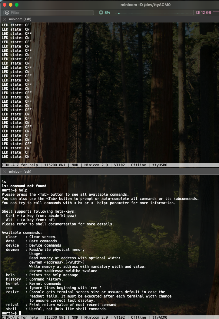
minicom으로 위쪽 터미널에선 uart0를, 아래쪽 uart1에 연결한 결과, 두 터미널이 서로 다른 역할을 하며 잘 동작하는것 볼 수 있음.

real-time system과 physical AI에 관심이 많습니다.