How to Size HVAC Ductwork: Manual J, D & S Explained
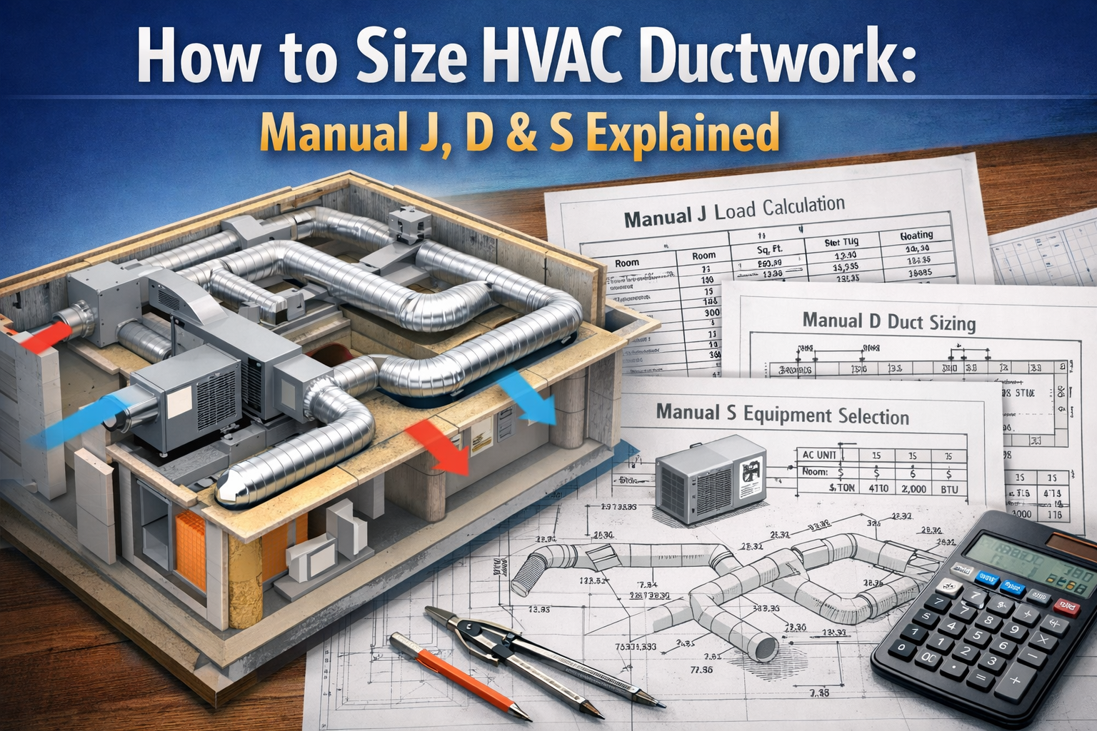
Proper HVAC duct sizing is the backbone of an efficient heating and cooling system. Yet, many projects still rely on rule-of-thumb methods that lead to airflow imbalance, energy waste, and occupant discomfort. To achieve optimal performance, professionals follow three critical methodologies: Manual J, Manual D, and Manual S. Together, they ensure accurate load calculation, equipment selection, and ductwork design.
This guide breaks down how these standards work together and highlights key ductwork design principles every contractor, engineer, and BIM professional should understand.
Why HVAC Duct Sizing Matters
Ductwork is not just a distribution system—it directly impacts system efficiency, indoor air quality, and lifecycle costs. Poorly sized ducts can cause:
- Static pressure issues
- Uneven airflow distribution
- Increased energy consumption
- Noise and vibration problems
- Reduced equipment lifespan
Accurate HVAC duct sizing ensures that conditioned air reaches every space efficiently while maintaining proper pressure balance.
Step 1: Load Calculation with Manual J
The process begins with Manual J, which determines the heating and cooling loads of a building. This calculation considers:
- Building orientation and envelope
- Insulation levels
- Window size and glazing type
- Occupancy and internal heat gains
- Local climate conditions
Manual J provides the BTU (British Thermal Units) required to maintain indoor comfort. Without this step, duct sizing becomes guesswork.
Key Technical Insight
Oversizing HVAC systems based on assumptions leads to short cycling, while undersizing results in insufficient cooling or heating. Manual J eliminates this uncertainty by providing data-driven load calculations.
Step 2: Equipment Selection with Manual S
Once the load is calculated, Manual S is used to select the appropriate HVAC equipment. This ensures that the system capacity aligns with the calculated load.
Manual S focuses on:
- Matching equipment capacity to load requirements
- Evaluating sensible vs. latent heat ratios
- Ensuring manufacturer performance data compliance
Why It Matters
Even with correct load calculations, improper equipment selection can disrupt airflow requirements. Since duct design depends on airflow (CFM), selecting the right unit is critical before moving to duct sizing.
Step 3: Duct Design with Manual D
After determining load and equipment, Manual D is used for duct sizing and layout. This step translates system requirements into an efficient air distribution network.
Manual D considers:
- Airflow requirements (CFM per room)
- Friction loss rate
- Duct material and roughness
- Static pressure constraints
- Equivalent length of duct runs
- Core Formula in Practice
Airflow (CFM) is calculated based on system capacity:
CFM = (BTU/hr) ÷ (1.08 × ΔT)
Where ΔT is the temperature difference between supply and return air.
This calculation forms the basis for determining duct dimensions.
Key Ductwork Design Principles
To ensure optimal performance, HVAC professionals must follow proven ductwork design principles:
1. Maintain Proper Air Velocity
Residential ducts: 600–900 FPM
Commercial ducts: 1000–2000 FPM
Excessive velocity causes noise, while low velocity reduces efficiency.
2. Minimize Pressure Loss
Design ducts with smooth transitions, gradual bends, and minimal restrictions to reduce friction losses.
3. Balanced Air Distribution
Each room must receive the correct airflow (CFM). This requires proper branch duct sizing and balancing dampers.
4. Optimize Duct Layout
Shorter, straighter duct runs improve efficiency. Avoid unnecessary turns and long flexible duct sections.
5. Static Pressure Management
Total external static pressure (TESP) must stay within equipment limits. Poor pressure management leads to airflow imbalance and system strain.
Common Mistakes in HVAC Duct Sizing
Even experienced professionals sometimes overlook critical aspects:
- Skipping Manual J calculations
- Using oversized ducts assuming “bigger is better”
- Ignoring return air design
- Poor sealing and insulation
- Overuse of flexible ducts
These errors compromise system efficiency and increase operational costs.
Role of BIM and Digital Tools in Duct Sizing
Modern HVAC design increasingly relies on BIM tools for precision and coordination. Platforms like Revit MEP and computational tools help:
- Automate airflow calculations
- Simulate pressure loss and system performance
- Detect clashes in duct routing
- Optimize space utilization in ceiling voids
Integrating BIM-based duct design improves accuracy and reduces rework during construction.
Best Practices for Accurate HVAC Duct Sizing
To ensure high-performance systems:
- Always start with Manual J load calculations
- Select equipment using Manual S guidelines
- Design ducts using Manual D standards
- Validate airflow using software simulations
- Perform field testing and balancing (TAB)
Following this structured approach ensures compliance with industry standards and enhances system reliability.
Conclusion
HVAC duct sizing is not a standalone task—it’s part of a coordinated process involving load calculation, equipment selection, and airflow design. By applying Manual J, D, and S, professionals can create systems that deliver consistent comfort, energy efficiency, and long-term performance.
For AEC professionals and contractors, mastering these methodologies is essential to staying competitive in a market that increasingly demands precision and sustainability. Whether you’re designing residential systems or complex commercial projects, adhering to these standards ensures your HVAC systems perform as intended from day one.