Pseudo-LiDAR from Visual Depth Estimation: Bridging the Gap in 3D Object Detection for Autonomous Driving
논문리뷰

mono type depthmap and bev

기본용어
voxel : pixel + volume : 2D(pixel) → 3D(+volume ) 로 표현한 것
camera parameter(calibration) : 2D → 3D로 바꿔주는 방식
disparty cost volumne (더 정확한 3D 포인트 클라우드 추정할 수 있다.) - 스테레오 비전원리를 활용해 2D이미지를 3D point cloud를 생성하기 위한 요소.
Cost volume : 두 영상의 강도(Intensity)의 차이를 픽셀 단위로 계산하여 유사도를 측정하는 것
depth cost volume : 양쪽 이미지 매칭을 통해 이미지간 차이로 depth 추정을 하는 알고리즘 → pseudo-LiDAR point cloud를 구성하게 된다.
commodity = stereo camera
스테레오 매칭 알고리즘
- 매칭비용 계산(matching cost computation)
- 비용 정합(cost aggregation) - cost volume의 정보를 정합해 계산 → 신뢰도 증가
- 시차 계산, 최적화(disparty computation / optimization) - 거리변환을 가능하게 한다.
- 시차 정제 (disparty)

disparity : 가까이 있는 물체를 따라가려면 변화량이 커야한다 이 변화량을 말하는 것이 시차(disparity)
bin : small region in the 3D space, point 그룹화 시키는데 사용된다.
tensor T is a 3D grid that represents the occupancy of each bin in the 3D space.
본 논문에서의 제안 :
이전 연구들과 같이 생성한 Depth Map을 추가적인 채널로 사용하지 않고, 픽셀에 에 대응하는 를 추출하는 것을 제안
(depth)
(width)
(height)
위 수식을 이용해 개의 점으로 이루어진 point cloud 데이터를 생성 + 진짜 라이다의 경우 LiDAR 센서는 범위를 벗어나게 되면 감지를 못하기 때문에 범위 밖 point들을 버리는 post processing을 거칩
본 논문에서는 AVOD, frustum PointNet 을 사용
AVOD : BEV로 변환한 object detection
frustum pointnet : 2d-object를 3d로 projection한 후 object detection
성능하락원인
1) 인접한 픽셀이지만 물리적으로 멀리 떨어져 있는 경우
2) 하나의 object라도 여러 depth scale을 갖는 경우
기본 개념 정리
https://www.youtube.com/watch?v=hUVyDabn1Mg
stereo disparity estimation : 수평 오프셋을 갖는 한 쌍의 카메라로부터 캡처된 좌우 한 쌍의 영상에서 해당 픽셀들의 수평 위치 차이를 추정하는 과정

는 각각 calibration(구경 측정)을 통해 측정된다. ⇒ 이렇게 4개의 equation을 통해서 x,y,z를 찾아낼 수 있다.

차이를 disparity 라고 부른다.
disparity will increase as the depth(z) decreases - 맨 오른 쪽 수식과 연관지어서 보면 된다.
how large should window be? →
if window size = 5 pixels → sensitive to noise
window size = 30 pixels → poor localization
⇒ solution : adaptive window method →
BEV(Brid’s Eye View) : common perspective used in autonomous driving applications where the view is from above the vehicle, looking down on the scene
monocular depth estimation : method of estimating the depth of objects in a scene using a single camera image.
기존 논문에서는 monocular 3D detection의 경우 많은 논문들이 depth 정보를 만들어내 detection을 진행 → 이때 부정확한 depth로 인해 LIDAR detector에 비해 성능이 낮게 나옴
이 논문에서는 depth로 인해 성능 차이를 내는 것이 아니라고 주장
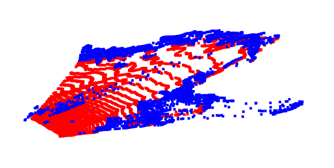
3D object detection에 더 어울리는 representation은 point cloud이기 때문에 LiDAR detector보다 낮은 성능을 내는 것이라고 주장함. 이 논문은 image로 depth map 을 생성한 뒤 estimated depth map을 통해 Pseudo-LiDAR 즉 point cloud representation 의 data를 생성 → LiDAR detector를 이용해 3D object detection진행
Introduction
Pseudo-LiDAR 의 낮은 정확도의 원인은 depth정보의 부재가 아닌 data의 representation문제라고 주장함.
image → depth map(생성) → Pseudo-LiDAR로 LiDAR신호와 비슷하게 data 생성 → 기존과 다른 representation올 3D object detection 진행
KITTI(Karlsruhe Institute of Technology and Toyota Technological Institute) 에서 SOTA 달성
해당 논문에서는 기존의 depth 정확도 차이를 image-based 방식의 3D objective detection(기존방식)를 사용해 측정하지만 point cloud 형식의 data표현이 3D objective detection에 사용되는 Convolution 구조에 더 적합하다고 한다. → image 와 depth map으로 진행하면 성능 차이가 발생하게 된다 ⇒ representation을 바꿔서 사용해보자
point cloud 방식의 경우 BEV 상에서는 shape or size가 depth에 대해서 불변한다. 하지만 image 의 경우에는 변한다. image 상에서는 물체가 멀어지면 size 가 작아지고 shape도 달라지기 때문에 멀어지면 detection이 어려워진다.
Solution - Two step
- estimating the dense pixel depth from stereo imagery
- back-projecting pixels into a 3D point cloud
Approach

- make image using steres or monocular → make dense depth map(Steres disparity estimation - PSMNET, Monocular depth estimation - DORN)
- make 3D point cloud using depth map and back-projection (AVOD, F-PointNet)
pseudo lidar++ 알고리즘 사용 + 3d bounding box(yolo3) 사용해본 결과, kitti dataset
depthmap

object detection

BEV
reference
https://techblog-history-younghunjo1.tistory.com/search/Object Detection
1, 2, 3 세대 스테레오 매칭 기술 소개


이렇게 유용한 정보를 공유해주셔서 감사합니다.