Introduction to Verilog
While putting a few transistors on an integrated circuit (IC) was a miracle when it happened, technology improvements have advanced the VLSI (very large scale integration) field continually. The early integrated circuits belonged to SSI (small-scale integration), MSI (medium-scale integration), or LSI (large-scale integration) categories depending on the density of integration.
SSI referred to ICs with 1 to 20 gates, MSI referred
to ICs with 20 to 200 gates, and LSI referred to devices with 200 to a few thousand
gates. Many popular building blocks such as adders, multiplexers, decoders, registers, and counters are available as MSI standard parts. When the term VLSI was
coined, devices with 10,000 gates were called VLSI chips. The boundaries between
the different categories are fuzzy today. Many modern microprocessors contain
more than 100 million transistors.
Computer-Aided Design
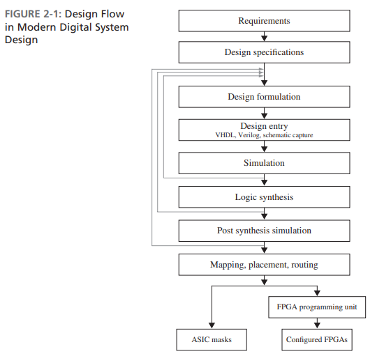
term::A design formulation is a conceptual level in designing, either at a block diagram level or at an algorithmic level.
term::A design entry, i.e. schematic capture, is entering the design conceptualized in the formulation step into the CDA systems, e.g. VHDL, Verilog.
olog::A hardware description language (HDL) allows a digital system to be designed and debugged at a higher level of abstraction than schematic capture
term::A synthesis is conversion of the higher-level abstract
description of the design to actual components at the gate and flip-flop levels.
term::A netlist is the output of the synthesis tool, consisting of a list og gates and a list of interconnections, specifying how to interconnect them.
A design can be implemented in several different target technologies during determining specific realizations of the design.
olog::The design is mapped into specific target technology and placed into specific parts in the target ASIC or FPGA. The paths taken by the connections between components are decided during the routing.
Always Blocks Using Event Control Statement
An always block can use wait or event control statements instead of a sensitivity list.
always
begin
	rst=1;  // sequential statements
    @(posedge clk); // wait until posedge clk
    // more sequential statements
The wait statement is used as a level-sensitive event control. The general syntax of the wait statement is wait (boolean-expression)
always
begin
	wait (WR)
    	MEM = DATA_IN;
    wait (~WR)
    	DATA_OUT = MEM:
end
Delays in Verilog
olog::Delays in Verilog can be categorized into inertial delay, transport delay, and net delay.
// explicit continuous assignment
wire D;
assign #5 D = A && B;

//implicit continuous assignment
wire #5 D = A && B;

// net declaration
wire #5 D;
assign D = A && B;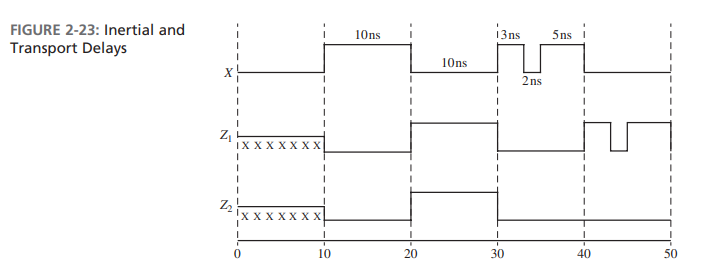
always @(X) begin
	Z1 <= #10 (X); // transport delay
end
assign #10 Z2 = X; // inertial delay
term::An inertial delay occurs when an input pulse that is shorter than the delay of the assignment and it does not propagate to the output.
olog::Inertial delay is intended to model gates and other devices that do not propagate short pulses from the input to the output.
term::A transport delsy delays an input signal by the specified delay time.
olog::Transport delay is intended to model the delay introduced by wiring.
term::A delayed assignment evaluates right hand side but doesn't assign to the lefg hand side until the delay has elapsed.
olog::To implement transport delay, an intra-assignment delay is possible, e.g. Z1 <= #10 (X).
term::Net delay refers to the time it takes from any driver on the net to change value to the time when the net value is updated and propagated further.
wire c1;
wire #10 c2; // net delay on wire c2

assign #30 c1 = a ||b; // inertial delay
assign #20 c2 = a||b; // inertial delay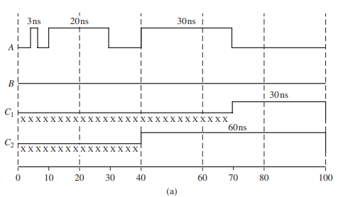
wire #3 d; // net delay
assign #7 d = y; // inertial dealy

wire #7 e; // net delay
assign #3 e = y; //inertial delay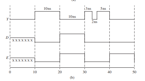
The assign statement for D works with a 7ns inertial delay and rejects any
pulse below 7ns. Hence D rejects the 3ns, 2ns and 5ns pulses in Y.
The 3ns net
delay from the wire statement is added to the signal that comes out from the assign statement.
Compilation, Simulation, and Synthesis of Verilog Code
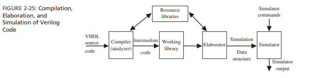
olog::There are three phases in the simulation of Verilog code: analysis (compilation), elaboration, and simulation.
term::An elaboratin is a phase where the design must have the modules being instantiated linked to the modules being defined, the parameters propagated among the various modules, and hierarchical references resolved before the simulation.
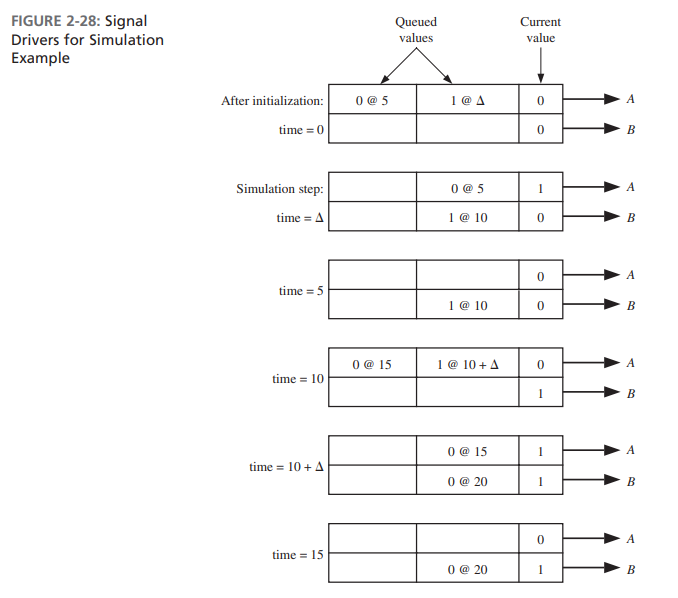
olog::During elaboration, a driver is created for each signal.
term::Each driver holds the current value of a signal and a queue of future signal values.
Each time a signal is scheduled to change in the future, the new value is placed in the queue along with the time at which the change is scheduled.
A memory storage is allocated for the required signals; the interconnections among the port signals are specified; and a mechanism is established for executing the Verilog statements in the proper sequence. The resulting data structure represents the digital system being simulated.
olog::The simulation process consists of an initialization phase and actual simulation.
term:: A discrete event simulation uses discrete steps as passage of time.
term::The initialization phase is used to give an initial value to the signal.
To facilitate correct initialization, the initial value can be specified in the Verilog model.
olog::A design consists of connected threads of execution or processes. term::Processes are objects that can be evaluated, that may have state, and that can respond to changes on their inputs to produce outputs.
olog::Processes include modules, initial and always procedural blocks, continuous assignments, procedural assignment statements, system tasks, and so forth.
term::Every change in value of a net or variable in the circuit being simulated is considered an update event.
When an update event is executed, all the processes that are sensitive to that event are evaluated in an arbitrary order.
term::An evaluation event is the evalution of a process.
term::A simulation time is used to refer to the time value maintained by the simulator to model the actual time it would take for the circuit being simulated.
olog::The events are kept on an event queue, to keep track of the events and to make sure they are processed in the correct order by the simulation time.
term::Scheduling an event is putting an event on the queue.
term::A monitor event is an event that shall be processed after all the active, inactive, and non-blocking assign update events are processed.
term::A future event occurs at some future simulation time
olog::Future events are divided into future inactive events and future non-blocking assignment update events.
Verilog Event queue
The Verilog event queue is logically segmented into five different regions
1. Active event region
Events that occur at the current simulation time are in this region.
Events can be added to any of the five regions but can be removed only from this region.
Events can be processed in any order from within this region. (This freedom to choose any active event for immediate processing is an essential source of non-determinism in the Verilog HDL.)
2. Inactive event region
Events that occur at the current simulation time but that shall be processed after all the active events are processed are in this region.
Blocking assignments with zero delays are in this region until they get moved
later to the active region.
3. Non-blocking assign update region
Events that have been evaluated during some previous simulation time but that shall be assigned at this simulation time after all the active and inactive events are processed are in this region.
4. Monitor event region
Monitor evetnts are in this region.
5. Future event region
Future events are in this region.
When each Verilog statement is processed, events are added to the various
queue regions according to the following convention for each type of statement:
Continuous assignment—evaluate RHS and add to active region as an active
update event.
Procedural continuous assign—evaluate RHS and add to active region as an
update event
Blocking assignment with delay—compute RHS and put into future event
region for time after delay.
Blocking assignment with no delay—compute RHS and put into inactive region
for current time.
Non-blocking assignment with no delay—compute RHS and schedule as non-blocking assign update event for current time if zero delay.
Non-blocking assignment with delay—compute RHS and schedule as non-blocking assign update event for future time if zero delay.
$monitor and $strobe system tasks—create monitor events for these system
tasks. (These events are continuously reenabled in every successive time step.)
term::A simulation cycle is a processing of all the active events.
For each simulation time, the following actions are performed in order
Process all active update events. (Whenever there is an active update event, the corresponding object is modified and new events are added to the various event queue regions for other processes sensitive to this update.)
Then activate all inactive events for that time (and process them because now
they are active).
Then activate all non-blocking assign update events and process them.
Then activate all monitor events and process them.
Advance time to the next event time and repeat from step i.
All of these five steps happen at the same time, but the events occur in the order active, inactive, non-blocking update, and monitor events.
Basically, the simulator works as follows with “<=”:
whenever a component input changes, the output is scheduled to change after the specified delay or after if no delay is specified.
When all events for the current time have been processed, simulated time is advanced to the next time at which an event is specified.
When time is advanced by a finite amount (1ns for example), the counter is reset and simulation resumes.
Real time does not advance again until all events associated with the current simulation time have been processed
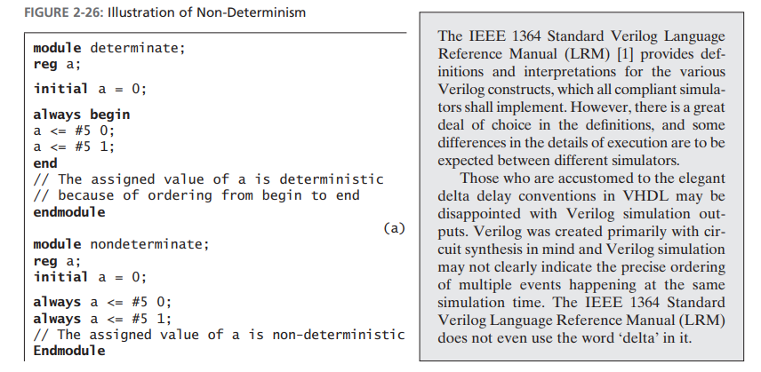
events are added to the event queue in source code order because of the begin . . . end, and the two updates are performed in source order as well.
The two always blocks are concurrent with respect to each other and there is no ordering between them. Hence the assigned value of a is non-deterministic
Simulation with Multiple Processes
olog::If a model contains more than one process, all processes execute concurrently with other processes. If there are concurrent statements outside always statements, they also execute concurrently.
olog:: Statements inside of each always block execute sequentially.
A process takes no time to execute unless it has wait statements in it.\
module twoprocess;
begin
	reg a, b;
    initial begin
    	a = 0;
        b = 0;
   	end

    // Process 1
    always @(b) begin
    	a <= 1;
        a <= #5 0;
    end

    // Process 2
    always @(a) begin
    	if (a)
        	b <= #10 ~b;
    end
endmodule
term::An event is a change in a signal.
Verilog simulators use event-driven simulation.
Each time an event occurs, any processes that have been waiting on the event are executed in zero time, and any resulting signal changes are queued up to occur at some future time.
When all the active
processes are finished executing, simulation time is advanced to the time for which the next event is scheduled, and the simulator processes that event.
This continues until either no more events have been scheduled or the simulation time limit is reached.
Inertial delays can now be explained in the following manner. Each input
change causes the simulator to schedule a change, which is scheduled to occur after the specified delay; however, if another input change happens before the specified delay has elapsed, the first change is dequeued from the simulation driver queue. Hence only pulses wider than the specified delay appear at the output
Writing synthesizable Verilog
- Use an edge-triggered clock in the sensitivity list using the posedge or
negedge keywords. - Use non-blocking assignments—that is, “<=” inside
alwaysblocks although it is possible to get sequential hardware by certain uses of the blocking “=” operator. - Do not mix blocking and non-blocking statements in an
alwaysblock. - Do not make assignments to the same variable from more than one
always
block. This is not a compile-time error and hence may go unnoticed. - Avoid unwanted latches by assigning a value to combinational output signals in every possible execution path in the always block.
This can be done by including else clauses for if statements specifying all cases for case statements or have a default clause at the end, or unconditionally assigning default values to all combinational output signals
at the beginning of the always block - Do not use initial blocks. Initial blocks are usually ignored during synthesis, except in some FPGA synthesis tools.
- Do not use delays (either delayed assignment or delayed evaluation). Delays are ignored during synthesis
- If possible, use concurrent assignments (assign) to design combinational
logic. - It is possible to use procedural assignments (always blocks) to design either combinational logic or sequential logic.
- When procedural assignments (always blocks) are used for combinational
logic, use blocking assignments (e.g., ‘=’). In Verilog 2001 or later, use
always@* to avoid accidental omission of signals from sensitivity lists. - When procedural assignments (always block) are used for sequential logic,
use non-blocking assignments (e.g., ‘<=’).
Modeling Hardware
1, If delays are not to be modeled, use blocking assignments (e.g., A = B)
for combinational logic and non-blocking assignments (e.g., A <= B) for
sequential logic.
2. In blocking assignments with no delay specification (e.g., A = B), the new
values are assigned immediately without any delta delays. However, in non-blocking assignments with no delay specification (e.g., A <= B), the change
is scheduled to occur after a delta time
3. To model combinational logic with inertial delays, use delayed evaluation
blocking statements (e.g., #10 A = B;)
4. To model combinational logic with transport delays, use delayed assignment non-blocking assignments (e.g., A <= #10 B;). This has to be inside
an always statement, because non-blocking assignments cannot be outside
always statements
5. To model sequential logic with delays, use delayed assignment non-blocking assignments (e.g., A <= #10 B;). This has to be inside an always
statement because non-blocking assignments cannot be outside always
statements
6. Use inertial delays if pulse-rejection behavior is required. If inertial delays are used, remember this fact when checking simulation outputs. If input
pulses are narrower than the inertial delay values, output changes will not occur and not paying attention to this fact may make a designer think that
the model is wrong, even when the model is fine.
7. Do not make assignments to the same variable from more than one always
block. Since this is not a compile-time error, it can lead to hard debugging
challenges. It may appear that the circuit is working at times and not working at times
To verify Hardware
- Although all types of assignment statements can be used in verification
models, use blocking assignments if possible. - When delays are used, pay attention to inertial behavior.
- Use initial blocks to hard code test stimulus values.
- Use parameters for creating constants so test benches can easily be modified.
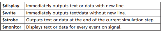
- Be aware of the differences between display, $strobe and $monitor so that wrong conclusions are not made about correctly working circuits.monitor displays every time one of its parameters changes.
display outputs values exactly where it is executed
Behavioral and Structual Verilog
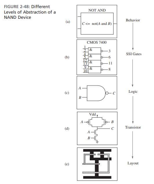
Verilog allows you to create design descriptions at multiple levels of
abstraction. The most common ones are behavioral models, data flow (RTL) models,and structural models.
term::Behavioral Verilog models describe the circuit or system at a high level of abstraction without implying any particular structure or technology, but only the overall behavior is specified.
term::Dataflow model specifies data path and control signals and describes in terms of the data transfer between registers, viewing system as registers with control logic,
term::Structural models is at a low level of abstraction and the components used and the structure of the interconnection between the components are clearly specified. Structural models may be detailed enough to specify use of particular gates and flip-flops.
Constants
The `define is one of the compiler directives in Verilog and is used to define a number or an expression for a meaningful string.
The localparam can be used to define constants that should not be changed.
Functions
The functions should be executed in zero time delay, which means that the functions cannot include timing delay information. The functions can have any number of inputs but can return only a single output.
function <range or type> function_name
	input [declarations]
    <declarations> // reg, parameter, integer, etc.
    begin
    sequential statements
    end
endfunction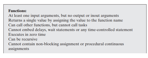
Task
Tasks can return any number of values.
task task_name
	input [declarations]
    output [declarations]
    <declarations> // reg, parameter, integer, etc.
 	begin
    sequentail statements
    end
end task_name;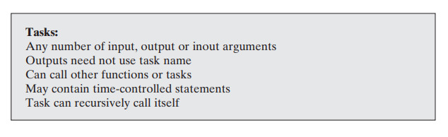
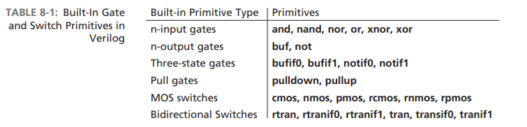
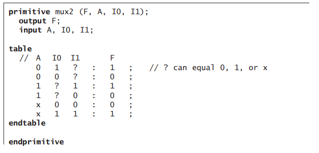
Primitives
Built-in
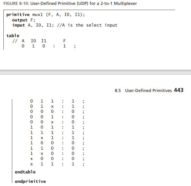
User-defined
The functionality of the primitive is defined with a truth table or state table, starting with the keyword table and ending with the keyword endtable.
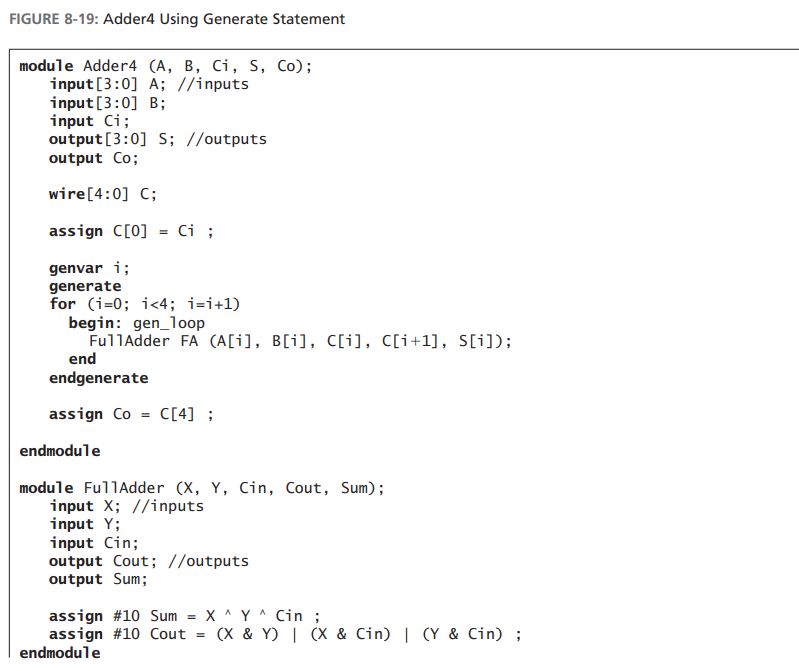
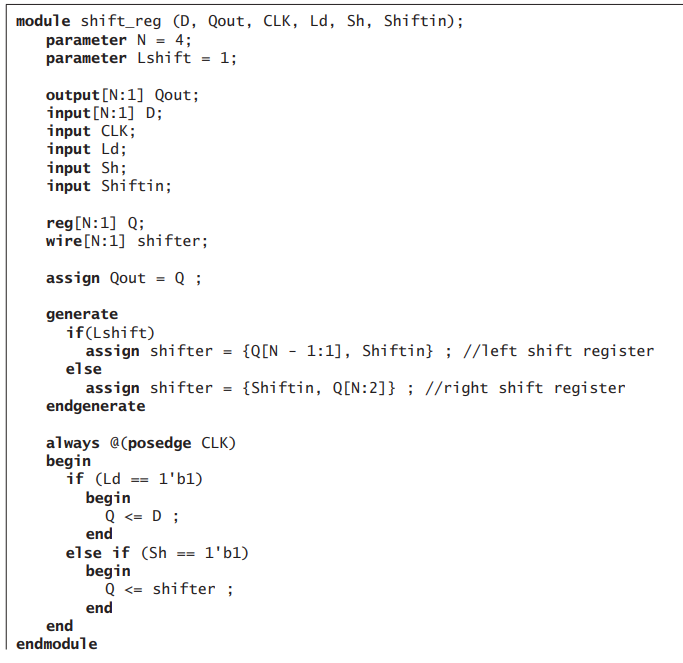
Generate
When an iterative array of identical operations or module instance is required, the generate statement provides an easy way of instantiating these components.
Conditional generate
Compiler Directives
define
The directive define creates a macro for text substitution.
include
This compiler directive is used to insert the contents of one source file into another file during compilation (i.e., for file inclusion).
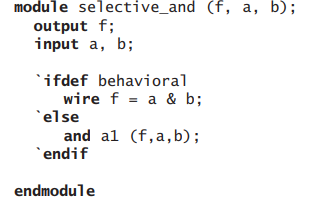
ifdef
Selectively including behavioral, structural, or switch-level models as
desired.
Selectively including different timing or structural information.
Selectively including different stimuli for different runs under different
scenarios.
Selectively adapting the module functionality to similar but different needs
from different customers
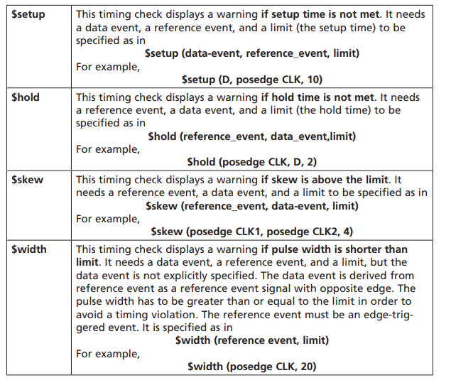
Timing Checks
Timing checks must be within specify blocks.