Verilog Testbench
Description
term::A Verilog testbench is a simulation environment used to verify the functionality and correctness of a digital design described in the Verilog HDL.
term::A Design Under Test, DUT, is the Verilog module or design to test.
How to work with testbench
Working with testbench is compatible with TDD. See FM23 for more.
Architecture
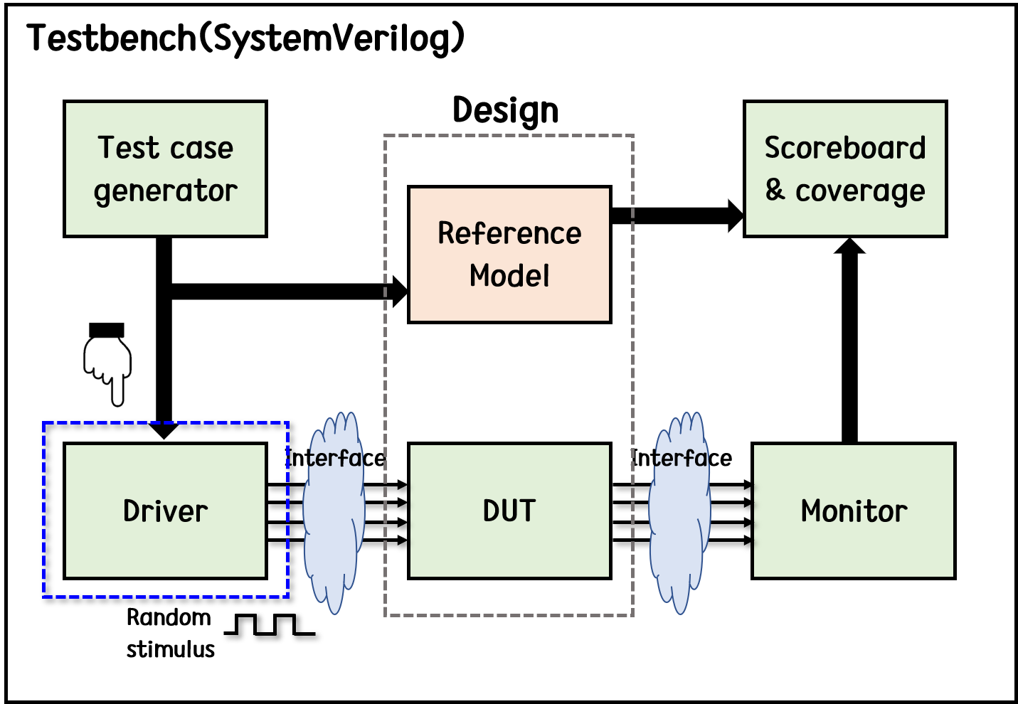
The testbench is implemented as a separate top-level Verilog module and consist of non-synthesizable verilog code which generates inputs to the design and checks that the outputs are correct.
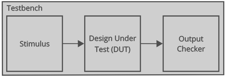
olog::A testbench is responsible for generating input stimuli for the DUt, capturing its output, and comparing it with expected outputs.
term::A test stimulus is a input pattern or sequence of the testbench, usually implemented with function and tasks.
Since testbenches are used for simulation purposes, they don't have to synthesizable, enabling constructs such as initial or system task, $display.
Types of testbenches
| Testbench | Input/Output Generation | Error Checking |
|---|---|---|
| Simple | Manual | Manual |
| Self-checking | Manual | Automatic |
| Automatic | Automatic | Automatic |
module silly(
	input a,
    input b,
    input c,
    output y
);
	assign y = ~b & ~c | a & ~b;
endmodule
Simple
Simple testbench instantiates the design under test and applies a series of inputs.
The outputs have to be observed and compared using a simulator program.
module tb_silly();
	reg a, b, c;
    wire y;

    silly dut(
    	.a(a),
        .b(b),
        .c(c)
    );

    initial begin
    	{a, b, c} = 0;
        #10;
        c = 1;
        #10
        b = 1, c=0;
        # 10
        c = 1;
        # 10;
        a = 1; b = 0; c = 0;
        #10;
    end
endmodule
👍Easy to design
👎Not scaleable
Self-checking
olog::A self-checking testbench includes a statement to check the current state such as $display.
module tb_silly();
	reg a, b, c;
    wire y;

    silly dut(
    	.a(a),
        .b(b),
        .c(c)
    );

    initial begin
    	{a, b, c} = 0;
        #10;
        if (y !== 1) $display("000 failed");
        c = 1;
        #10
        if (y !== 0) $display("000 failed");
        b = 1, c=0;
        # 10
        if (y !== 0) $display("010 failed");
    end
endmodule
👍Easy to design
👍Checker will print whenever an error occurs
👎Not scaleable
👎Easy to make an error in hardcoded values
Self-checking with testvectors
term::A test vector is a list of inputs and expected outputs.
This can be manually or automatically created using a golden model.
The testbench generate clock for assigning inputs, reading outputs, and reads test vectors file into array. Then assign inputs, and gets expexcted outputs from DUT. Finally, it compares outputs to expected outputs and report errors.
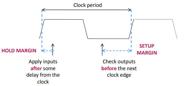
A testbench clock is used to synchronize I/O, the same clock can be used for the DUT clock.
Inputs are applied following a hold margin.
Apply inputs with some delay after clock, since real circuits may suffer from hold violations.
Outputs are sampled before the next clock edge.
Use a clock signal for assigning inputs, reading outputs and test one testvector for each clock cycle.
cat tv_silly.tv
000_1
001_0
...
module tb_silly();
reg clk, reset;
reg a, b, c, yexpected;
wire y;
reg [31:0] vectornum, errors;
reg [3:0] testvectors[100000:0];
// Instantiate device under test
silly dut(
.a(a),
.b(b),
.c(c)
);
// Generate Clock
initial begin
forever clk = ~clk;
end
// Read Testvectors into an Array
initial begin
$readmemb("tv_silly.tv", testvectors);
vectornum = 0;
errors = 0;
reset = 1;
#27
reset = 0;
end
// Assign Inputs and Expected Outputs
always @(posedge clk) begin
#1; {a, b, c, yexpected} = testvectors[vectornum];
end
// Compare Outputs with Expected Outputs
always @(negedge clk) begin
if (~reset) begin
if (y !== yexpected) begin
$display("Error: inputs = %b", {a, b, c});
$display(" outputs = %b (%b exp)",y,yexpected);
errors = errors + 1;
end
vectornum = vectornum + 1;
if (testvectors[vectornum] === 4'bx) begin
$display("%d tests completed with %d errors", vectornum, errors);
$finish;
end
end
end👍Easy to design
👍Checker will print whenever an error occurs
👍No need to change hardcoded values for different tests
👎More scalable, but still limited by reading a file
👎Error-prone depending on source of testvectors
Automatic
term::A golden model represents the ideal circuit behavior, written not only in verilog but c, python, matlab, etc.
The behavior of the circuit is compared against a golden model in the automatic testbench.
How to write a testbench
tb_module_name # (
  // If the module uses parameters they are connected here
  .ParameterName (<parameter_value>)
)
<instance_name> (
  // Connection to the module ports
  .port_name (signal_name),
  .port_name (signal_name)
);- Declare top-level testbench module
// This comment describes the following module.
module tb_module_name;
endmodule- Declare signals for DUT connections
reg en;
reg rstn;
reg d; // To derive input d of the DUT
reg prev_q; // To ensure q has not change when en=0
wire q; // To tap output from DUT- Instatiate DUT
module_name dut (
	.clk(clk),
    .en(en),
    .rstn(rstn),
    .d(d),
    .q(q)
);- Initialize testbench variables
initial begin
	d <= 0;
    en <= 0;
    rstn <= 0;
end
Or you could use function for this.
function void init();
	d <= 0;
    en <= 0;
    rstn <= 0;
endfunction

initial begin
	init();

    #10
end- Write test stimulus
task reset_release();
	#10 rstn <= 1;
endtask

task test_1();
	for (i = 0; i < 5; i = i+1) begin
    	delay = $random;
        delay2 = $random;
        #(delay2) en <= ~en;
        #(delay) d <= i;

        checker(d, en, rstn, q);
        prev_q <= q;
    end
endtask

initial begin
	init();

    reset_release();
test_1();- Write checker code
You can use c or python using std output. In that case, what verilog is respobsible of is to correctly output. However, it is also a good practice to write checker in sole verilog.
funciton checker(
	input d,
    input en,
    input rstn,
    input q
);
	#1;
    if (!rstn) begin
    	if (q != 0)
        	$error("Q is not 0 during resetn!");
    end else begin
    	if (en) begin
        	if (q != d)
            	$error("Q does not follow D when EN is high!");
        end else begin
        	if (q != prev_q)
            	$error("Q does not get latched!");
            end
        end
endfunction
See Single Port RAM or 4-bit counter for more.
Related Syntaxes
initial block
term::An initial block is a type of procedural block that is executed only once, at the beginning of a simulation.
olog::The statements in an initial block should be blocking.
Code within initial block is not synthesizable.
initial block is always needed in testbench to initialize signals.
forever block
term::An forever block is a loop block that is executed infinitely during the simulaiton.
This is useful to make a clock signal.
olog::Any loop statement must be contained in a procedural block or generate block.[Jo20]
System Tasks
$display, $monitor, $time
$dump
Further Topics
- SPEC https://www.youtube.com/watch?v=anRPs_owfwk
- Performance Modeling
- Transaction-level modeling
- Testing에는 여러 level이 있다. Logic-level, Board-levle, System-level 등등... 각각의 목적, 이런 level들 사이의 상관관계, 사용하는 언어 또는 프레임워크에 대한 이해도가 낮다.
References
Capkun, S., Gurkaynak, F. (2014). Design of Digital Circuits[Pdf]. Using Verilog for Testbenches. Retrieved April 8, 2024, from https://syssec.ethz.ch/content/dam/ethz/special-interest/infk/inst-infsec/system-security-group-dam/education/Digitaltechnik_14/14_Verilog_Testbenches.pdf
Chip Verify. (n.d.). Veriog Testbench. https://www.chipverify.com/verilog/verilog-testbench
John. (2020). FPGA Tutorial. How to Write a Basic Verilog Testbench. Retrieved April 8, 2024, from https://fpgatutorial.com/how-to-write-a-basic-verilog-testbench/
Dream Sailor. (2020). [Digital 회로 설계] SystemVerilog로 Testbench 설계하기 3편(Image driver). https://dreamsailor.tistory.com/20
Satfety Zone. (2023). [Verilog Testbench] dumpvars와 dumpfile을 시뮬레이션하자. https://safetyzone.tistory.com/entry/Verilog-Testbench-dumpvars%EC%99%80-dumpfile%EC%9D%84-%EC%9D%B4%ED%95%B4%ED%95%98%EC%97%AC
Peter fab. (n.d.). Value Change Dump (VCD) File. https://peterfab.com/ref/verilog/verilog_renerta/mobile/source/vrg00056.htm
Mutlu, O. (2022). Digital Design and Computer Architecture[Pdf]. Lecture 9: Timing adn Verification. Retrieved April 8, 2024, from https://safari.ethz.ch/digitaltechnik/spring2022/lib/exe/fetch.php?media=onur-digitaldesign_comparch-2022-lecture8-timing-and-verification-beforelecture.pdf
Fowler, M. (2023). Tet Driven Development. https://martinfowler.com/bliki/TestDrivenDevelopment.html
Roth, C. H., John, L. K., & Lee, B. K. (2016). Digital systems design using Verilog. Cengage Learning.