the ARM Cortex-M3 Processor - 6
Exceptions 7
7.1 EXCEPTION TYPES
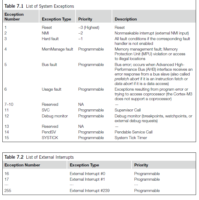
The Cortex M3 provides a feature-packed exception architecture that supports a number of system exceptions and external interrupts. Exceptions are numbered 1-15 for system exceptions and 16 and above for external interrupt inputs. Most of the exceptions have programmable priority, and a few have fixed priority.
Cortex-M3 chips can have different numbers of external interrupt inputs(from 1 to 240) and different numbers of prioirty levels. This is because chip designers can configure the Cortex-M3 design source code for different needs.
Exception types 1-15 are system exceptions, Exceptions of type 16 or above are external interrupt inputs.
The value of the current running exceptions is indicated by the special register Interrupt Program Status register(IPSR), or from the Nested Vectored Interrupt Controllers(NVICs) Interrupt Control State register.
Note that here the interrupt number refers to the interrupt inputs to the Cortex M3 NVIC. In actual microcontroller products of system on chips, the external interrupt input pin number might not match the interrupt input number on the NVIC. For example, some of the first few interrupt inputs might be assigned to internal peripherals, and external itnerrupt pins could be assigned to the next couple of interrupt inputs. Therefore, you need to check the chip manufacturer's datasheets to determin the numbering of the interrupts.
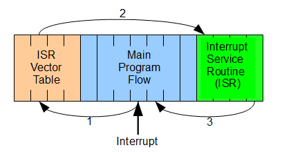
When an enabled exception occurs but cannot be carried out immediately(for instance, if a higher prioirty interrupt service routine is running or if the interrupt mask register is set), it will be pended(except forsoem fault exceptions). This means that a register(pending status) will hold the exception reqest untill the exception can be carried out. This is different from traditional ARM processsors. Previously, the devices that generate interrupt, such as interrupt request(IRQ)/fast interrupt request(FIQ), must hold the request until they are served. Now, with the pending registers in the NVIC, an occurred interrupt will be handled even if the source requesting the interrupt deasserts its request signal.
7.2 DEFINITIONS OF PRIORITY
In the Cortex-M3, whether and when an exception can becarried out can be affected by the prioirty of the exception. A higher prioirty(smaller number in prioirty level) exception can preempt a lower prioirty (larger numer in prioirty ) exception; this is the nested excetpion/interrupt scenario. Some of the exceptions(reset, NMI, and hard fault) have fixed prioirty levels. They are negative numbers to indicate that they are of higher priority than other exceptions. Other exceptions have programable prioirty levels.
The Cortex-M3 supports three fixed highest-prioirty levels and up to 256 levels of programmable priority. However, most Cortex M3 chips have fewer supported levels for example 8,16,32, and so on. When a Cortex-M3 chip or SoC is being designed, designers can customize it to obtain the number of levels required. This reduction of levels is implemented by cutting out the LSB part of the priority configuration registers.
For example ,if only 3 bits of priority level are implemented in the desgin, a priority -level configuration register will look like 7.1
Because bit 4 to bit 0 are not implemneted, they are always read as zero, and writes to these bits will be ignored. With this setup, we have possible priority levels of 0x00, 0x20, 0x40, 0x60, 0x80 ...
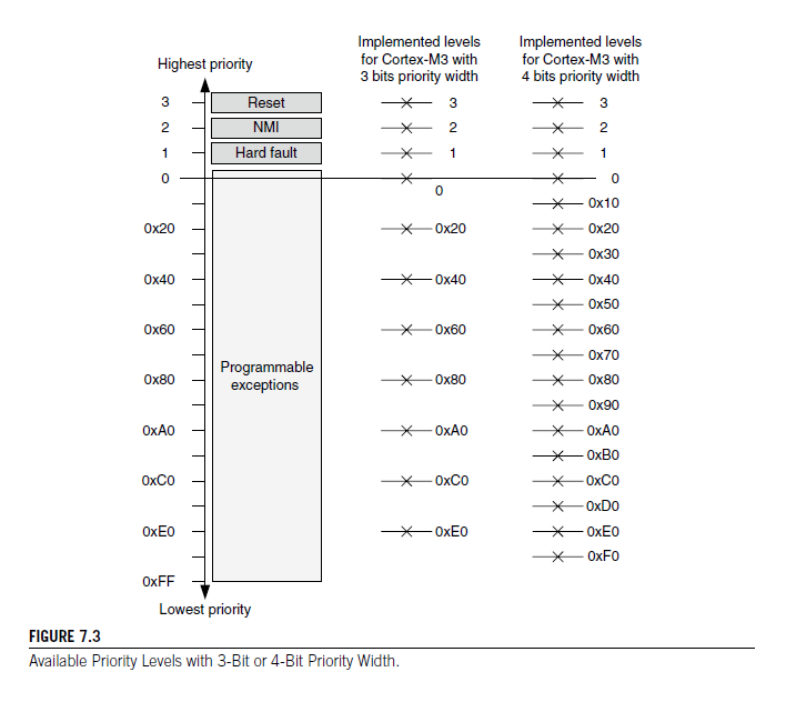
If more bits are implemented, more priority levels will be available. However, more priority bits can also increase gate counts and hence the power consumption. For the Cortex M3 the minimum number of implemented priority register widths is 3 bits(eight levels).
7.3 VECTOR TABLES
When an exception takes place and is being handled by the cortex m3, the processor will need to locate the starting address of the exception handler. This informaition is stored in the vector table in the memory.
By default the vector table starts at memory address 0, and the vector address is arranged according to the exception number times four(see Table 7.6).
Since the address 0x0 should be boot code, usuaklly it will be either Flash memory or ROM devices, and the value cannot be changed at run time. However, the vector table can be relocated to other memory locations in the code or RAM region where the RAM is so that we can change the hnadlers during run time. This is done by setting a register in the NVIC called the vector table offset register(address 0xE00ED08). The address offset should be aligned to the vector table size, extended to the next larger power of 2. For example, if there are 32 IRQ inputs, the total number of exceptions will be 32 + 16 (system exceptions) = 48. Extending it to the power of 2 makes it 64. Multiplying it by 4(4 bytes per vector) makes it 256 bytes(0x100). Therefore, the vector table offset can be programmed as 0x0, 0x100, 0x200, and so on. The vector table offset register contains the items shown in Table 7.7.
In applications where you want to allow dynamic changing of exception handlers, in the beginning of the boot image, you need to have the following ( at a minimum ) :
- Initial main stack pointer value
- Reset vector
- NMI vector
- Hard Fault Vector
| Address | Exception Number | Value(Word Size) |
|---|---|---|
| 0x00000000 | - | MSP iniial value |
| 0x00000004 | - | Reset Vector(program counter initial value) |
| 0x00000008 | - | NMI handler starting address |
| 0x0000000C | - | Hard fault handler starting address |
| ... | ... | Otherhandler starting address |
7.4 INTERRUPT INPUTS AND PENDING BEHAVIOR
This section describe the behavior of IRQ inputs and pending behavior. It also applies to NMI input, except that an NMI will be executing an NMI handler, halted by a debugger, or locked up because of some serious system error.
When an interrupt input is asserted, it will be pended, which means it is put into a state of waiting for the processor to process the request. Even if the interrupt source deasserts the interrupt, the pended interrupt status will still cause the interrupt handler to be executed when the priority is allowed. Once the interrupt handler is started, the pending status is cleared automatically. This is hown in Figure 7.9.
However, if the pending status is cleared before the processor starts responding to the pended interrupt(for example, the interrupt was not taken immediately because PRIMASK/FAULTMASK is set to 1, and the pending status was cleared by software writing to NVIC interrupt control register), the interrupt can be cancelled. The pending status of the interrupt can be accessed in the NVIC and is writable, so you can clear a pending interrupt or use software to pend a new interrupt by setting the pending register.
인터럽트 입력이 단언되면 대기 상태로 전환되어 처리기가 요청을 처리하기를 기다리는 상태가 됩니다. 인터럽트 소스가 인터럽트를 해제하더라도 대기 중인 인터럽트 상태는 우선순위가 허용될 때 인터럽트 핸들러가 실행되도록합니다. 인터럽트 핸들러가 시작되면 대기 중인 상태는 자동으로 지워집니다. 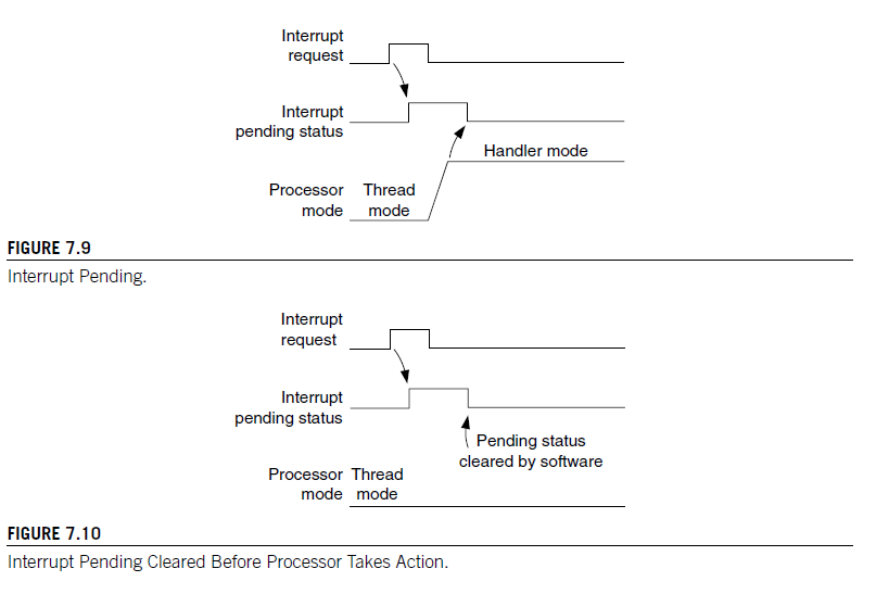
When the processor starts to execute an interrupt, the interrupt becomes active and the pending bit will be cleared automatically. When an interrupt is active, you cannot start processing the same interrupt again, until the interrupt service routine is terminated with an interrupt return(also called an exception exit, as dsicussed in Chapter 9). Then the active status is cleared, and the interrupt can be processed again if the pending status is 1. It is possible to repend an interrupt beforte the end of the interrup service routine
If an interrupt source continues to hold the interrupt request signal active, the interrupt will be pended again at the end of the interupt service routine as shown in Figure. This is just like the traditional ARM7.
If an interrupt is pulsed several times before the processor starts processing it, it will be treatd as one single interrupt request as illustrated in Figure. If an interrupt isdeasserted and then pulsed again during the
인터럽트가 활성화되어 있는 동안 인터럽트 서비스 루틴이 인터럽트 반환(또는 예외 종료)으로 종료될 때까지 동일한 인터럽트를 다시 처리할 수 없습니다(제9장에서 설명한 바와 같음). 그런 다음 활성 상태가 지워지고 대기 상태가 1이면 인터럽트를 다시 처리할 수 있습니다. 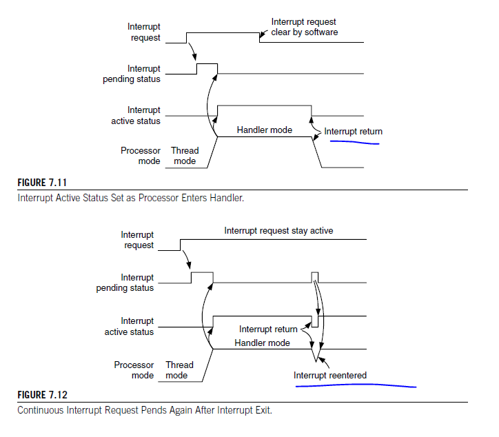
7.5 FAULT EXCEPTIONS
A number of system exceptions are useful for fault handling. There are several categories of faults:
-
Bus faults
-
Memory management Faults
-
Usage faults
-
Hard faults
7.5.1 Bus Faults
Bus faults are produced when an error response is received during a transfer on the AHB interfaces. It can happen at these stages :
-
Instruction fetch, commonly called prefetch abort
-
Data read/write, commmonly called data abort
In the Cortex-M3, bus faults can also occur during the following :
-
Stack PUSH in the beginning of interrupt processing, called a stacking error
-
Stack POP at the end of interrupt processing, called an unstacking error
-
Reading of an interrupt vector address(vector fetch) when the processor starts the interrupt-handling sequecne ( a special case classified as a hard fault )
When these types of bus faults(except vector fetches) take place and if the bus fault handler is enabled and no other exceptions with the same or higher priority are running. the bus fault andler will be execute.
If the bus fault handler is enabled but at the same time the core receives another exception with higher priority, the bus fault happens in an exception handler that has the smae or higher priority than the bus fault handler, the hard fault handler will be executed instead. If another bus fualt takes place whne running the hard fualt handler, the core wii enter a lock up state.
What Can Cause AHB Error Responses?
Bus Faults occur when an error reponse is received on the AHB bus. The common cause are as follows :
-
Attempts to access an invalid memory region ( for example, a memory location with no memory attached )
-
The device is not ready to accept a transfer(for example, trying to access SDRAM without initializing the SDRAM controller)
-
Attempts to carry out a transfer with a transfer size not supported by the target device(for examplt, doing a byte access to a peripheral register that must be accessed as a word)
-
The device does not accept the transfer for various reasons(for example, a peripheral that can only be programed at the privileged access level.
To enable the bus fault handler, you need to set the BUSFAULTENA bit in the system handler Control and state reigister in the NVIC. Before doing that, make sure that the bus fault handler starting address is set up in the vector table if the vector table has been relocated to RAM.
Hence, how do you find out what went wrong when the processor entered the bus fault handler? The NVIC has a number of Fault Status registers(FSRs). One of them is the Bus Fault Status register. From this register, the bus fault handler can find out if the fulat was caused by data/instruction access or an interrupt staking or unstacking opertiaon
따라서, 프로세서가 버스 오류 핸들러에 진입했을 때 무엇이 잘못되었는지 어떻게 알 수 있을까요? NVIC에는 여러 개의 Fault Status 레지스터(FSR)가 있습니다. 이 중 하나는 Bus Fault Status 레지스터(BFSR)입니다. 버스 오류 핸들러는 이 레지스터를 통해 오류가 데이터/명령어 액세스인지 아니면 인터럽트 스태킹 또는 언스태킹 작업인지 확인할 수 있습니다.For precise bus faults, the offending instruction can be located by the stacked program counter, and if the BFARVALID bit in BFSR is set, it is also possible to determine the memory locaiton that caused the bus fault. This is done by reading another NVIC register called Bus Fault Address register (BFAR). However, the same information is not a available for imprecise bus faults becuase by the time the processor receives the error, the processor could have already executed a number of other instruction
문제가 되는 명령어는 스택된 프로그램 카운터로 확인할 수 있으며, BFSR의 BFARVALID 비트가 설정된 경우, 버스 오류를 일으킨 메모리 위치를 결정할 수도 있습니다. 이는 Bus Fault Address 레지스터(BFAR)라는 다른 NVIC 레지스터를 읽어서 수행됩니다. 그러나 정밀하지 않은 버스 오류의 경우 동일한 정보를 얻을 수 없습니다. 왜냐하면 프로세서가 오류를 수신할 때까지 이미 다른 명령어를 실행했을 수 있기 때문입니다.
PRECISE AND IMPRECISE BUS FAULT
Bus faults caused by data accesses can be further classified as precise or imprecise. In imprecise bus faults the fault is caused by an already completed opertiona(such as a buffered write) that might have occurred a numboer of clock cycles ago. Precise bus faults are caused by the last completed operation -- for xample, a memory read is precise on the Cortex-M3 becuase the instruction cannot be completed until it receives the data.
The programmer's model for BFSR is as follows : It is 8 bits wide and can be accessed through byte transfer to address 0xE000ED29 or with a word transfer to address 0xE000ED28 with BFSR in the second byte. The error indication bit is cleared when a 1 is written to it.
Table 7.8 Bus Fault Status Register (0xE00ED29)
Bits Name Type Reset Value Description 7 BFARVALID - 0 Indicates BFAR is valid 6:5 - - - - 4 STKERR R/Wc 0 Stacking Error 3 UNSTKERR R/Wc 0 Unstacking Error 2 IMPRECISERR R/Wc 0 Imprecise data access violation 1 PRECISERR R/Wc 0 Precise data access violation 0 IBUSERR R/Wc 0 Instruction access violation 7.5.2 Memory Management Faults
Memory management faults can be caused by memory accesses that violate the setup in the MPU or by certain illegal accesses(for example, trying to execute code from nonexecutable memory regions), which can trigger the fault, even if no MPU is presented.
Some of the common MPU faults include the following: -
Access to memory regions not defined in MPU setup
-
Writing to read only regions
-
An access in the user state to a region defined as privileged access only
When a memory management fault occurs and if the memory management handler is enable, the memory management fault handler will be executed. If the fault occurs at the same time a higher priority exception takes place, the other exceptions will be handled first and the memory management fault will be pended. If the processor is already running an exception handler with the same of higer priority of if the memory management fault handler is not enabled, the hard fault handler will be executed instead.
프로세서가 이미 동일한 또는 더 높은 우선순위의 예외 핸들러를 실행 중이거나 메모리 관리 오류 핸들러가 활성화되어 있지 않은 경우, 대신 하드 폴트 핸들러가 실행됩니다.If a memory management fault takes place inside the hard fault handler or the NMI handler, the processor will enter the lockup state.
Like the bus fault handler, the memory management fault handler needs to be enabled. This is done by the MEMFAULTENA bit in SYstem handler Control and State register in the NVIC. If the vector table has been relocated to RAM, the memory management fault handler starting addres should be set up in the vector table first.
  메모리 관리 오류가 하드 폴트 핸들러나 NMI 핸들러 내에서 발생하는 경우, 프로세서는 잠김 상태에 들어갑니다.

버스 오류 핸들러와 마찬가지로, 메모리 관리 오류 핸들러도 활성화되어야 합니다. 이는 NVIC의 SYstem handler Control and State 레지스터의 MEMFAULTENA 비트를 통해 수행됩니다. 만약 벡터 테이블이 RAM으로 이동되었다면, 메모리 관리 오류 핸들러의 시작 주소는 먼저 벡터 테이블에 설정되어야 합니다.
The NVIC contains a Memory Management Fault Status register(MFSR) to indicate the cause of the memroy management fault. If the status register indicated that the fault is a data access violation(DACCVIOL bit) ir an instruction access violation(IACCVIOL bit), the offending code can be located by the stacked program counter. If the MMARVALID bit in the MFSR is set, it is also possible to determine the memory address location access violation(IACCVIOL bit), the offending code can be located by the stacked program counter. If the MMARVALID bit in the MFSR is set, it is also possible to determin the memory address location that caused the fault from the Memory Management Address register (MMAR) in ther NVIC.
The programmer's model for the MFSR is shown in Table 7.9. It is 8 bits wide and can be accessed through byte transfer or with a word transfer to address 0x#00ED28, with the MFSR in the lowest byte. As with other FSRs, the fault status bit can be cleared by writing 1 to the bit.
Table 7.9 Memory Management Fault Status Register(0xE00ED28)
| Bits | Name | Type | Reset Value | Description |
|---|---|---|---|---|
| 7 | MMARVALID | -- | 0 | Indicates the MMAR is valid |
| 6:5 | - | - | - | - |
| 4 | MSTKERR | R/Wc | 0 | Stacking error |
| 3 | MUNSTRKERR | R/Wc | 0 | Unstacking error |
| 2 | - | - | - | - |
| 1 | DACCVIOL | R/Wc | 0 | Data access violation |
| 0 | IACCVIOL | R/Wc | 0 | Instruction access violation |
스택 오류(Stacking Error)는 인터럽트나 예외 처리 중에 발생하는 오류입니다. 스택은 예외 발생 시에 프로세서 상태를 저장하는 데 사용되는 메모리 영역입니다. 스택 오류가 발생하면 예외 처리 중에 스택에 데이터를 저장하거나 스택에서 데이터를 추출하는 과정에서 문제가 발생했음을 의미합니다.

언스택 오류(Unstacking Error)는 예외 처리가 끝날 때 스택에서 데이터를 추출하는 과정에서 발생하는 오류입니다. 예외 처리가 완료되면 이전 상태로 복원하기 위해 스택에서 데이터를 추출합니다. 언스택 오류가 발생하면 스택에서 데이터를 추출하는 과정에서 문제가 발생했음을 의미합니다.
7.5.3 Usage Faults
Usage faults can be caused by a number of things
-
Undefined instructions
-
Coprocessor instructions ( the Cortex-M3 processor does not support a coprocessor, but it is possible to use the fault exception mechanism to run software compiled for ohter Cortex processors through coprocessor emulation )
-
Trying to switch to the ARM state(software can use this faulting mechanism to test whether the processor it is running on supports the ARM code; because the Cortex-M3 does not support the ARM state, a usage fault takes place if there's an attempt to switch)
-
Invalid interrupt return
-
Unaligned memory accesses using multiple load or store instructions
7.6 SUPERVISOR CALL AND PENDABLE SERVICE CALL
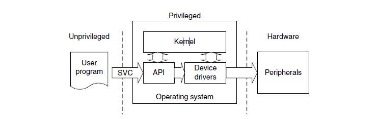
Supervisor Call(SVC) and Pendable Service Call(PendSV) are two exceptions targeted at software and operting systems. SVC is for generating system fuction calls. For example, instead of allowing user programs to directly access hardware, an operation system may provide access to hardware through an SVC.
So when a user program wants to use certain hardware, it generates the SVC exception using SVC instructions, and then the software exception handler in the operating system is executed and provides the service the user application requested.
In this way, access to hardware is under the control of the OS, which can procide a more robust system by preventing hte user applications from directly accessing the hardware.
SVC can also make software more portable because the user application does not need to know the programming details of the hardware. The user program will only need to know the application programming interface unction ID and parameters; the actual hardware-level programming is handled by device divers.
SVC exception is generated using the SVC instruction. An immediate value is required for this instruction, which works as a parameter-passing method. The SVC exception handler can then extract instruction, which works as a paramater-passing method. The SVC exception handler can then extract the parameter and determin what action it needs to perform. For example,
SVC #0x3 ; Call SVC function 3
The traditional syntax for SVC is also acceptable(without the "#" )
SVC 0x3 ; call SVC function 3
For C language development, the SVC instruction can be generated using __svc function( for ARM C Compiler), or using inline
When the SVC handler is executed, you can determine the immediate data value in the SVC instruction by reading the stacked program counter value.
When the SVC handler is executed, you can determine the immediate data value in the SVC instruction by reading the stacked program counter value, the nreading the instruction from that address and masking out the unneeded bits. If the system usess a Process Stack Pointer for user applications, you might need to determine which stack was used first. This can be determined from the link register value when the handler is enterd.
SVC AND SOFTWARE INTERRUPT INSTRUCTION (ARM 7)
If you have used tradition ARM processors(such as the ARM7), you might know that they have a software interrupt instruction (SWI).
The SVC has a similar function, and in fact the binary encoding of SVC instructions is the same as SWI in ARM7.
Becuase of the interrupt priority model in the Cortex-M3, you cannot use SVC inside an SVC handler . Doing wo will result in ausage fault.
