Why Touch Coordinates Do Not Match the Sensor Grid
A touch controller reports an X position of 3072, but the display is only 800 pixels wide. Is the driver returning invalid data?
Not necessarily. A controller's coordinate range can differ from the display's pixel dimensions. It can also be much finer than the electrode matrix that produced the measurement.
For an embedded UI developer, these are three separate spaces: the physical sensor, the reported coordinates, and the rendered screen. Understanding the boundaries between them makes position errors easier to investigate.
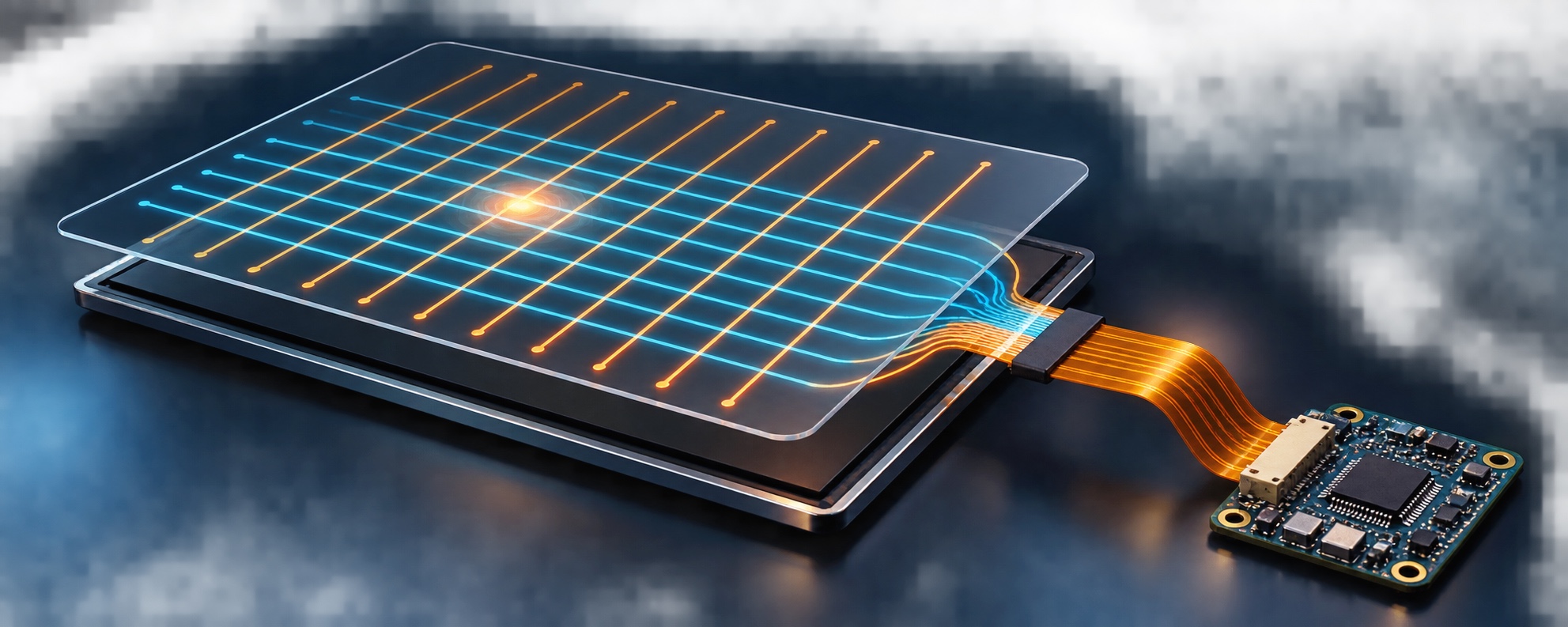
The electrodes do not form a pixel address map
Touchscreen Channels are the transmit and receive channels used by the controller to measure the sensor. In a mutual-capacitance panel, the controller measures coupling between TX and RX electrodes. A finger changes that coupling near the contact area.
The resulting measurements support a position estimate. There is no requirement for one electrode intersection per LCD pixel.
As a hypothetical example, a full 16 TX × 28 RX matrix contains 448 sensing intersections. That number does not specify the coordinate range available to software. It also does not specify how many simultaneous fingers the controller can report.
This matters when reading a specification: a larger coordinate range is not proof of greater physical accuracy. A device can report many numerical positions while its measurements still contain noise or systematic error.
Convert the reported range, not the channel count
Suppose a hypothetical controller reports both axes from 0 through 4095. The application renders onto an 800 × 480 pixel surface.
For a simple mapping with aligned axes, no rotation, and the full sensor area covering the full display, the calculation is:
screen_x = round(raw_x * 799 / 4095)
screen_y = round(raw_y * 479 / 4095)
The display's last pixel indices are 799 and 479. Using 800 and 480 as the output endpoints would allow coordinates outside that pixel index range.
Here, raw_x means a controller-reported coordinate before this mapping, not a raw capacitance measurement.
A reported position of approximately (2048, 2048) maps near the display center. The electrode count does not appear in the calculation.
If the input range has a nonzero minimum, subtract it before scaling:
screen_x = round((raw_x - x_min) * (width - 1) / (x_max - x_min))This assumes x_max > x_min, valid input, and arithmetic with enough precision. In production code, define how to handle out-of-range values and avoid accidental integer truncation.
Before implementing any conversion, check whether the driver, compositor, or UI framework already performs it. Applying the same scaling twice creates another position error.
Rotation introduces a different problem
Scaling adjusts the range. Rotation changes which direction each axis represents.
For example, a finger moving horizontally across the mounted screen might primarily change the reported Y coordinate. That observation suggests an axis swap somewhere in the mapping. If the relevant coordinate decreases in the direction the application expects it to increase, an inversion may also be needed.
Linux's common touchscreen bindings define properties for axis inversion and swapping. They also define touchscreen-size-x and touchscreen-size-y in terms of the maximum reported coordinate plus one.
Those properties are not TX/RX electrode counts. Check support in the specific driver before changing them, and track transformations applied elsewhere in the software stack.
Use five locations to expose mapping errors
A quick check can start with the center and four locations near the corners. Use visible targets slightly inside the active area rather than assuming a finger can reach the exact numerical endpoint.
For each target, record the reported coordinate before application mapping and the final UI position.
Look for patterns:
- A left-right reversal suggests an orientation problem.
- A correct center with increasing displacement toward the edges suggests a range or scale mismatch.
- Correct positions before UI mapping, followed by incorrect positions afterward, focus the investigation on that transformation.
- Missing or unstable contacts before mapping require investigation beyond a coordinate formula.
These observations narrow the search; they do not establish a root cause by themselves. Five targets are a useful initial check, not a complete accuracy assessment.
Keep contact tracking out of the coordinate calculation
Multi-touch adds contact identity to the position data. Linux Type B reporting uses slots to maintain individual contacts, so an application can distinguish two fingers moving at once.
A slot is not a sensor row, an RX input, or a display region. Apply the appropriate coordinate mapping to each reported contact while preserving its identity through movement and release.
For the integration notes, record the sensor's TX/RX configuration, the reported axis limits, the supported contact count, and the transformations used by the host as separate fields. When a touch lands on the wrong button, those details let you investigate the coordinate path without guessing from the screen size.