HAL 드라이브 코드를 분석해서 이해한 후 드라이브 없이 gpio를 제어할 것이다.
gpio clk 코드 분석
1. mx_gpio_init 확인
2. __HAL_RCC_GPIOC_CLK_ENABLE();
#define __HAL_RCC_GPIOC_CLK_ENABLE()   do { \
                                        __IO uint32_t tmpreg; \
                                        SET_BIT(RCC->APB2ENR, RCC_APB2ENR_IOPCEN);\
                                        /* Delay after an RCC peripheral clock enabling */\
                                        tmpreg = READ_BIT(RCC->APB2ENR, RCC_APB2ENR_IOPCEN);\
                                        UNUSED(tmpreg); \
                                      } while(0U)
UNUSED(tmpreg) : Warning 뜨지 않게 하기 위해 사용
SET_BIT(RCC->APB2ENR, RCC_APB2ENR_IOPCEN); 코드만 분석하기
3. SET_BIT(RCC->APB2ENR, RCC_APB2ENR_IOPCEN);
#define SET_BIT(REG, BIT) ((REG) |= (BIT))= or연산
(RCC->APB2ENR) |= (RCC_APB2ENR_IOPCEN)

*(0x40021018) |= 16

*(0x40021018) |= (1<<4)
4. 결론?
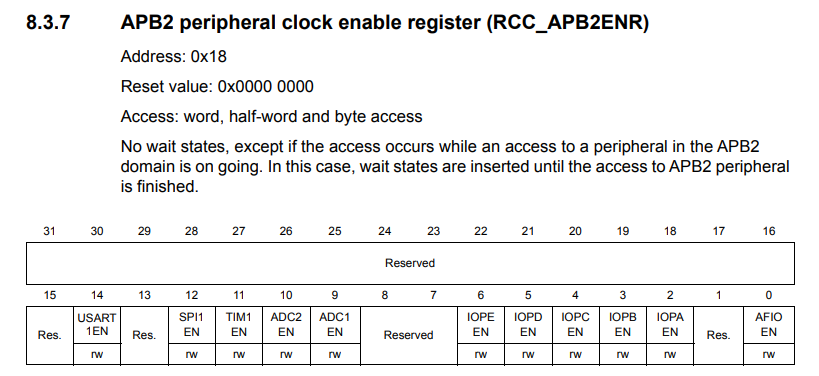
RCC : Reset and clock control
APB2 : 클럭 버스
Bits 4 : I/O port C clock enable
-> C port의 클럭 활성화
클럭?
컴퓨터에서 연산을 조정하는 타이밍 신호, 기준점이 된다
내부 클럭 : MCU 자체에서 발생시킴 -> 불안정
외부 클럭 : 보통 외부클럭을 많이 사용 -> 일정함
버스
장치마다 필요한 클럭이 다름
클럭이 같은 애들끼리 모아놓음
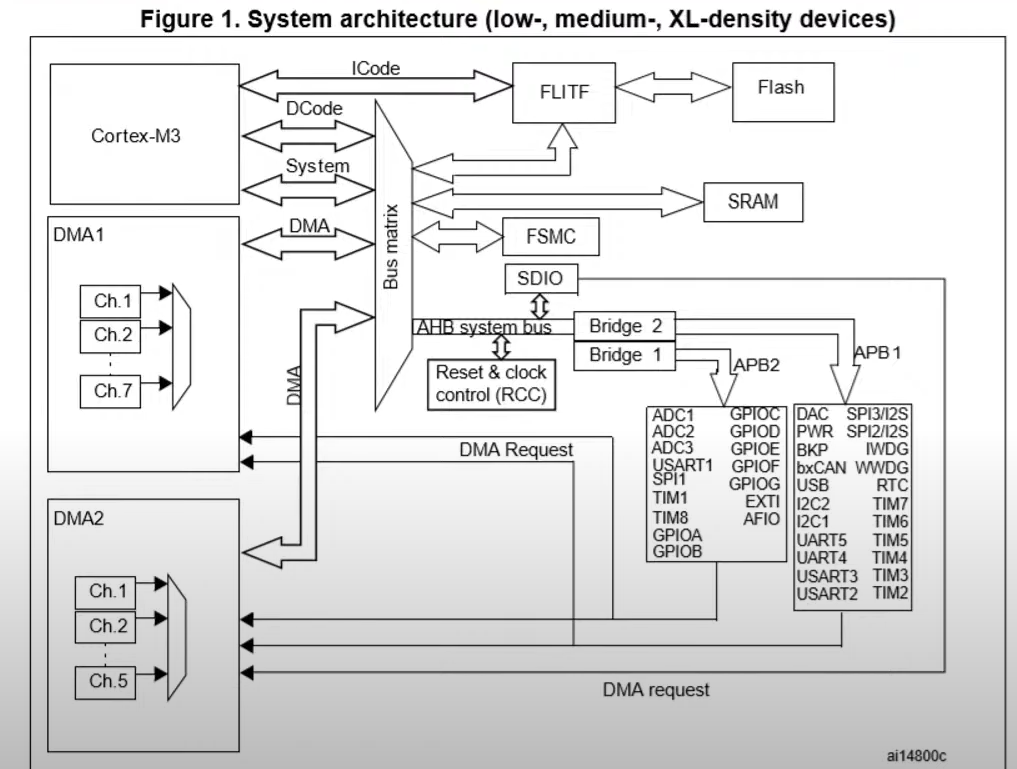
AHB(Advanced high performance Bus) : 빠른 클럭 버스
APB(Advanced Peripheral Bus) : 느린 클럭 버스
gpio output 코드분석
1. HAL_GPIO_WritePin(GPIO_LED_GPIO_Port, GPIO_LED_Pin, GPIO_PIN_SET);
void HAL_GPIO_WritePin(GPIO_TypeDef *GPIOx, uint16_t GPIO_Pin, GPIO_PinState PinState)
{
  /* Check the parameters */
  assert_param(IS_GPIO_PIN(GPIO_Pin));
  assert_param(IS_GPIO_PIN_ACTION(PinState));

  if (PinState != GPIO_PIN_RESET)
  {
    GPIOx->BSRR = GPIO_Pin;
  }
  else
  {
    GPIOx->BSRR = (uint32_t)GPIO_Pin << 16u;
  }
}
assert_param : 아무것도 안함
원래는 디버깅 메시지 출력을 위한것
GPIOx->BSRR : 0x40011010

gpio 그룹

#define GPIO_LED_GPIO_Port GPIOC
GPIOC : 0x40011000
gpio pin
#define GPIO_LED_Pin GPIO_PIN_13
GPIO_PIN_13 : 8192
-> Binary:10000000000000
-> HEX : 0X2000pin 상태
typedef enum
{
GPIO_PIN_RESET = 0u,
GPIO_PIN_SET // =1
} GPIO_PinState;
2. if (PinState != GPIO_PIN_RESET)
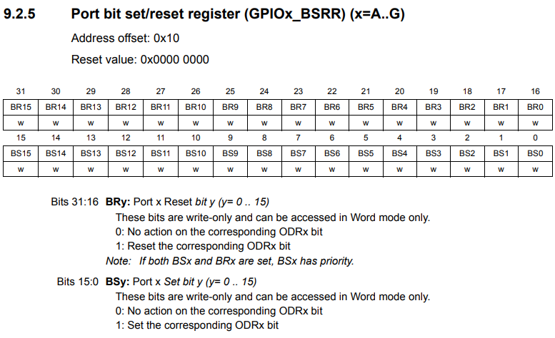
set = Bits 15:0
GPIOx->BSRR = GPIO_Pin;

*(0x40011010) = 0X2000

13번 - High
3. else
reset = Bits 31:16
GPIOx->BSRR = (uint32_t)GPIO_Pin << 16u;

*(0x40011010) = (0X2000 << 16)

29번 - low
실제 코드로 적용하기
/* Initialize all configured peripherals */
  //MX_GPIO_Init();  //주석처리
  /* USER CODE BEGIN 2 */

  // __HAL_RCC_GPIOC_CLK_ENABLE();
  volatile unsigned int * reg = 0x40021018;
  *reg |= 16;

  // 다음시간에 자세히 다룸
  GPIO_InitTypeDef GPIO_InitStruct = {0};
  GPIO_InitStruct.Pin = GPIO_LED_Pin;
  GPIO_InitStruct.Mode = GPIO_MODE_OUTPUT_PP;
  GPIO_InitStruct.Pull = GPIO_PULLDOWN;
  GPIO_InitStruct.Speed = GPIO_SPEED_FREQ_HIGH;
  HAL_GPIO_Init(GPIO_LED_GPIO_Port, &GPIO_InitStruct);
  /* USER CODE END 2 */

  /* Infinite loop */
  /* USER CODE BEGIN WHILE */

  volatile unsigned int *reg2 = 0x40011010;
  while (1)
  {
  	  //HAL_GPIO_WritePin(GPIO_LED_GPIO_Port, GPIO_LED_Pin, GPIO_PIN_SET);
	  *reg2 = 0x2000; //high - led off
	  HAL_Delay(1000);

	  *reg2 = (0x2000 << 16); // low - led on
	  HAL_Delay(1000);

    /* USER CODE END WHILE */

    /* USER CODE BEGIN 3 */
  }
  /* USER CODE END 3 */
}