저번 강의에서는 GPIO CLK 활성화, WritePin 처럼 LED 제어를 했다
이번에는 이어서 밑의 코드를 분석하고 실제로 적용해본다
GPIO_InitTypeDef GPIO_InitStruct = {0};

/*Configure GPIO pin : GPIO_LED_Pin */
  GPIO_InitStruct.Pin = GPIO_LED_Pin;
  GPIO_InitStruct.Mode = GPIO_MODE_OUTPUT_PP;
  GPIO_InitStruct.Pull = GPIO_PULLDOWN;
  GPIO_InitStruct.Speed = GPIO_SPEED_FREQ_HIGH;
  HAL_GPIO_Init(GPIO_LED_GPIO_Port, &GPIO_InitStruct);
코드 분석(GPIO 옵션 설정)
구조체
1. GPIO_InitTypeDef GPIO_InitStruct = {0};
typedef struct
{
  uint32_t Pin;
  uint32_t Mode;
  uint32_t Pull;
  uint32_t Speed;
} GPIO_InitTypeDef;
* uint32_t : 4바이트 간격
구조체에 설정값을 넣어준 것이다
  GPIO_InitStruct.Pin = GPIO_LED_Pin;           // PC13 , 8192 = 0x2000
  GPIO_InitStruct.Mode = GPIO_MODE_OUTPUT_PP;   //1
  GPIO_InitStruct.Pull = GPIO_PULLDOWN;         //2
  GPIO_InitStruct.Speed = GPIO_SPEED_FREQ_HIGH; //3
HAL_GPIO_Init(GPIO_LED_GPIO_Port, &GPIO_InitStruct);
- GPIOC의 주소 : 0x40011000
#define GPIO_LED_GPIO_Port GPIOC // 0x40011000HAL_GPIO_Init(GPIO_LED_GPIO_Port, &GPIO_InitStruct);
HAL_GPIO_Init(GPIOC의 주소, 구조체의 주소값);HAL_GPIO_Init 동작
1. 변수 선언, assert_param
void HAL_GPIO_Init(GPIO_TypeDef  *GPIOx, GPIO_InitTypeDef *GPIO_Init)
{
// 변수 선언
  uint32_t position = 0x00u;
  uint32_t ioposition;
  uint32_t iocurrent;
  uint32_t temp;
  uint32_t config = 0x00u;
  __IO uint32_t *configregister; /* Store the address of CRL or CRH register based on pin number */
  uint32_t registeroffset;       /* offset used during computation of CNF and MODE bits placement inside CRL or CRH register */

 // assert_param : (void)0U , 브레이크 포인트 걸리지 않음
  assert_param(IS_GPIO_ALL_INSTANCE(GPIOx));
  assert_param(IS_GPIO_PIN(GPIO_Init->Pin));
  assert_param(IS_GPIO_MODE(GPIO_Init->Mode));
2. while문
while문이 한번 실행될 때마다 position ++
pin 번호만큼 실행되고 종료
/* Configure the port pins */
  while (((GPIO_Init->Pin) >> position) != 0x00u)
  {
  ...
  position++;
  }
GPIO pin = 13
1 0000 0000 0000 -> position == 0
0 1000 0000 0000 -> position == 1
0 0100 0000 0000
...
0 0000 0000 0001
0 0000 0000 0000 -> position == 14일때 while문 종료
ioposition
position 값이 증가 할 때마다(while문이 한 번 돌 때) ioposition 값 증가
/* Get the IO position */
    ioposition = (0x01uL << position);
1
10
100
1000
10000
..
iocurrent
    /* Get the current IO position */
    iocurrent = (uint32_t)(GPIO_Init->Pin) & ioposition;
1 0000 0000 0000 : GPIO_Init->Pin
& 1 : ioposition
_________________
0 : iocurrentif문
if (iocurrent == ioposition)
    {
    ....
    }
1 0000 0000 0000 : GPIO_Init->Pin
& 1 0000 0000 0000 : ioposition
_________________
1 0000 0000 0000 : iocurrent
position = 13 ->
ioposition = 13 ->
iocurrent = ioposition 임
따라서 pin 이 몇 번인지 알기 위해서 만든 코드이다.
3. switch문
if (iocurrent == ioposition)
    {
      /* Check the Alternate function parameters */
      assert_param(IS_GPIO_AF_INSTANCE(GPIOx));

      /* Based on the required mode, filling config variable with MODEy[1:0] and CNFy[3:2] corresponding bits */
      switch (GPIO_Init->Mode)
      {
        /* If we are configuring the pin in OUTPUT push-pull mode */
        case GPIO_MODE_OUTPUT_PP:
          /* Check the GPIO speed parameter */
          assert_param(IS_GPIO_SPEED(GPIO_Init->Speed));
          config = GPIO_Init->Speed + GPIO_CR_CNF_GP_OUTPUT_PP;
          break;
          ...
       }
       ...
    }
GPIO_Init->Mode = GPIO_MODE_OUTPUT_PP 일 때

config = GPIO_Init->Speed + GPIO_CR_CNF_GP_OUTPUT_PP;

config = 3 + 0;
config = 3
switch문은 config 값 설정을 위한 것
4. configregister
configregister = (iocurrent < GPIO_PIN_8) ? &GPIOx->CRL : &GPIOx->CRH;삼항 연산자 : 8번 핀 이하? 이상?
이하 : CRL = 0x40011000
이상 : CRH = 0x40011004
iocurrent = 0x2000
GPIO_PIN_8 = 0x0100
현재 8핀 이상임

configregister = 0x40011004
5. registeroffset
registeroffset = (iocurrent < GPIO_PIN_8) ? (position << 2u) : ((position - 8u) << 2u);삼항 연산자 : 8번 핀 이하? 이상?
이하 : registeroffset = 52
이상 : registeroffset = 20
8번 핀 이상 :
registeroffset = 20
6. MODIFY_REG
MODIFY_REG((*configregister), ((GPIO_CRL_MODE0 | GPIO_CRL_CNF0) << registeroffset), (config << registeroffset));정의
#define MODIFY_REG(REG, CLEARMASK, SETMASK)
				  WRITE_REG((REG), (((READ_REG(REG)) & (~(CLEARMASK))) | (SETMASK)))
- REG = *configregister // *0x40011004
- CLEARMASK = (GPIO_CRL_MODE0 | GPIO_CRL_CNF0) << registeroffset // (3 | 12) << 20
GPIO_CRL_MODE0 = 3
GPIO_CRL_CNF0 = 12
(GPIO_CRL_MODE0 | GPIO_CRL_CNF0) = 15
- SETMASK = config << registeroffset // 3 << 20 WRITE_REG
#define WRITE_REG(REG, VAL) ((REG) = (VAL))REG = REG
VAL = (((READ_REG(REG)) & (~(CLEARMASK))) | (SETMASK))
-> *(0x40011004) = VALREAD_REG
#define READ_REG(REG) ((REG)) (((READ_REG(REG)) & (~(CLEARMASK))) : A & ~(B) 연산
: A에 이미 값이 있고 그 값을 원하는 부분(B)만 변경하고 싶을 때 사용
예시)
111100001 & ~(001100000)

  111100001
& 110011111
------------
  110000001
결론
HAL_GPIO_Init(GPIO_LED_GPIO_Port, &GPIO_InitStruct); 이 코드는 아래와 같은 동작을 한다
pin 번호에 따라
configregister = 0x40011004
registeroffset = 20

config = 3

정해지고

MODIFY_REG((*configregister), ((GPIO_CRL_MODE0 | GPIO_CRL_CNF0) << registeroffset), (config << registeroffset));
를 하는 코드이다
*(0x40011004) = (*(0x40011004) & ~(15UL <<20)) | (3 << 20)
GPIO 옵션 설정
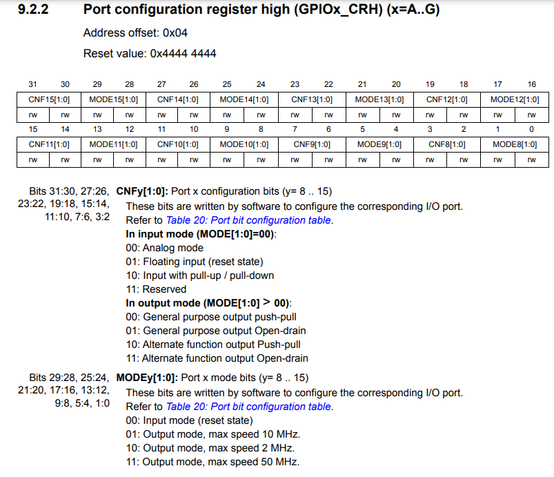
typedef struct
{
  __IO uint32_t CRL;
  __IO uint32_t CRH; -> 이 부분 조작
  __IO uint32_t IDR;
  __IO uint32_t ODR;
  __IO uint32_t BSRR;
  __IO uint32_t BRR;
  __IO uint32_t LCKR;
} GPIO_TypeDef;
원래는 데이터시트를 읽고 GPIO에 대하여 이해하고 학습해서 소스를 작성해야 하지만
역으로 샘플코드를 읽고 이해해서 GPIO에 대해 알아가는 방식이 더 빠르게 학습할 수 있는 방식이다
실제 코드 적용
  /* Initialize all configured peripherals */
  //MX_GPIO_Init();
  /* USER CODE BEGIN 2 */

  volatile unsigned int * reg = 0x40021018;
  *reg |= 16;

// GPIO 옵션 설정
  volatile unsigned int * reg2 = 0x40011004;
  *reg2 = (*reg2 & ~(15UL << 20U)) | (3U << 20U);

  /* USER CODE END 2 */

  /* Infinite loop */
  /* USER CODE BEGIN WHILE */
  volatile unsigned int *reg3 = 0x40011010;
  while (1)
  {
	  *reg3 = 0x2000; //high - led off
	  HAL_Delay(1000);

	  *reg3 = (0x2000 << 16); // low - led on
	  HAL_Delay(1000);

    /* USER CODE END WHILE */
    /* USER CODE BEGIN 3 */
  }