Heavy-Duty Electrical Cable Cleats for Complex Cable Installations
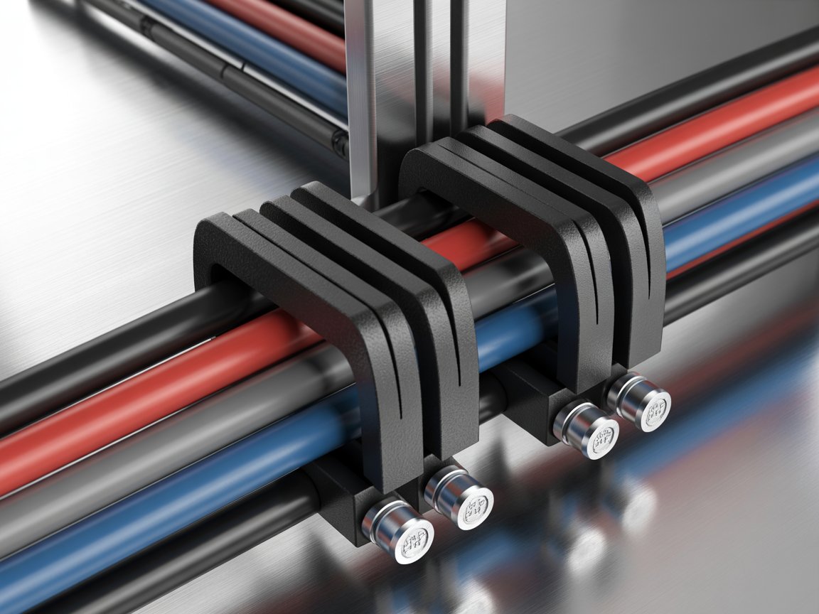
Heavy-duty electrical cable cleats are engineered restraints that secure single, trefoil, or multi-core power cables against short-circuit electromechanical forces, vibration, thermal expansion, and mechanical loads in complex installations such as tunnels, power plants, rail systems, oil & gas facilities, and high-voltage joint bays. Compliant with IEC 61914, they prevent cable damage, protect terminations, and maintain system integrity under peak fault currents often exceeding 100–190 kA. Proper selection and spacing based on cable diameter, formation, and calculated forces are essential for safety and compliance.
Heavy-Duty Electrical Cable Cleats deliver the mechanical strength required for demanding environments where standard clamps fail.
Key Takeaways
Heavy-duty cable cleats must be IEC 61914 tested and rated for the system’s peak short-circuit current.
Trefoil formation generates the highest forces; spacing typically maxes at 900 mm (use intermediate restraints beyond that).
Material choice (316L stainless steel, aluminium, high-performance polymer) depends on corrosion, temperature, and fire requirements.
Incorrect spacing, under-rated hardware, or over-tightening are the most common causes of failure.
Bespoke solutions solve restricted spaces, non-standard diameters, and complex routing in tunnels or joint bays.
Correct installation protects cables, terminations, and personnel while reducing long-term maintenance costs.
What Are Heavy-Duty Electrical Cable Cleats?
Cable cleats are devices designed to secure cables at intervals along their length. Unlike simple cable ties or clamps, heavy-duty versions are specifically engineered and third-party tested to resist the enormous lateral and axial forces generated during a short-circuit event.
These forces can reach tens of thousands of Newtons per metre. Without adequate restraint, cables can whip violently, damage insulation, stress terminations, or create secondary hazards. Heavy-duty cleats provide both retention and defined geometry—especially critical in trefoil arrangements used for three-phase power circuits.
They are classified under IEC 61914 for impact resistance, corrosion performance, temperature range, fire behaviour, and electromechanical force withstand. Leading manufacturers offer ranges covering cable diameters from roughly 10 mm to over 190 mm, with short-circuit ratings validated at specific fixing centres (commonly 300 mm, 600 mm, or 900 mm).
Why Complex Cable Installations Demand Heavy-Duty Solutions
Complex installations present unique challenges:
High peak fault currents (often >100 kA)
Restricted tray or duct widths
Vertical risers and long runs with thermal expansion
Hazardous or corrosive environments (offshore, tunnels, petrochemical)
Multiple cable configurations (single, trefoil, quad, matrix, joint-bay transpositions)
Need for fire-performance retention with critical circuits
In projects such as high-voltage tunnel systems or power-plant support structures, standard polymeric or light-duty cleats cannot deliver the required loop strength or corrosion resistance. Heavy-duty metallic (316L stainless steel or aluminium) and reinforced polymer designs, sometimes with LSF0H liners, become essential.
Benefits of Using Heavy-Duty Electrical Cable Cleats
Short-circuit safety — Contain electromagnetic forces and prevent cable movement that could damage insulation or supports.
System reliability — Protect terminations, joints, and equipment from transferred axial loads.
Compliance — Meet IEC 61914, BS 7671, and industry-specific requirements (rail, oil & gas, nuclear).
Longevity — Corrosion-resistant materials and proper liners extend service life in harsh environments.
Installation efficiency — Range-taking designs and hinged or strap options reduce SKU count and speed fixing, especially post-cable-pull.
Risk reduction — Lower probability of catastrophic failure during faults, protecting personnel and assets.
Design flexibility — Bespoke variants accommodate non-standard diameters, stacked configurations, or existing frameworks.
Types of Heavy-Duty Cable Cleats for Complex Installations
Single-bolt and two-bolt metallic cleats, typically made from 316L stainless steel or aluminium, suit single-core or parallel runs with high fault levels. They deliver high loop strength, excellent corrosion resistance, and stackable options, though they are heavier and require more precise sizing.
Trefoil and quad cleats, available in stainless steel, aluminium, or reinforced polymer, are designed for three- or four-core formations. They maintain correct geometry under high short-circuit ratings but are often diameter-specific or offer limited range-take.
Hinged and range-taking designs, usually stainless steel with polymer liners, work well with variable cable diameters and allow post-pull installation. They provide wide range-take and easier fixing, though careful torque control is needed.
Strap and intermediate restraints made from stainless steel strapping offer mid-span support for very high currents. They are lightweight and flexible in spacing but are normally used together with primary cleats.
Fire-performance cleats combine stainless steel with high-temperature liners and are intended for critical safety circuits. They withstand fire, shock, and water tests but come at a higher cost.
Bespoke and matrix solutions are custom fabricated for joint bays, restricted trays, and multi-row layouts. They provide an exact fit for complex arrangements, although lead times are longer.
Step-by-Step Guide to Cable Cleat Installation
Calculate forces and select the cleat
Determine peak short-circuit current (ip), cable outside diameter, and formation. Use the IEC 61914 formulae (Ft ≈ 0.17 × ip² / S for trefoil) and manufacturer loop-strength data to choose the correct rating and maximum spacing.
Verify materials and hardware
Confirm cleat, liners, and fixings (preferably A4/316 stainless) match environmental and load requirements. Reject non-compliant or mixed-manufacturer components on the same run.
Prepare the route
Ensure cable ladder, tray, or support structure can withstand the forces. Mark fixing centres accurately—tighten spacing on bends, risers, and near terminations/joints (often 300 mm).
Position and secure
Place the base, insert cables (trefoil orientation critical), close the cleat or strap, and torque to manufacturer values. Avoid over-tightening that damages the sheath. Use anti-galling compound on stainless threads.
Apply intermediate restraints if needed
For spacings beyond 900 mm in trefoil, install mid-point restraints. On vertical runs, consider alternating orientation.
Inspect and document
Check for correct torque, no cable bulging, full liner contact, and secure mounting. Record ratings and positions for compliance.
Common Mistakes to Avoid
Selecting by diameter alone without verifying short-circuit rating.
Exceeding recommended maximum spacing (especially on bends and verticals).
Using ordinary cable ties or non-rated clamps on power circuits.
Over- or under-tightening bolts.
Mounting on inadequate supports that will pull out under load.
Ignoring thermal expansion needs in long or jointed runs.
Mixing cleat brands or omitting specified liners/spacers.
Expert Tips for Complex Installations
Always request project-specific short-circuit test data or simulation when fault levels or cable sizes fall outside catalogue tables.
For tunnels or restricted widths, evaluate range-taking hinged designs or custom matrix assemblies early in the design phase.
On vertical trefoil runs, “alternative cleating” (180° rotation of successive cleats) improves axial retention.
Near terminations and joints, place an additional cleat close to the accessory to absorb expansion forces.
In corrosive or fire-risk zones, prioritise 316L stainless with LSF0H liners and verified fire-performance ratings.
Use manufacturer calculators or apps where available to confirm spacing and part numbers quickly.
Comparison: Heavy-Duty vs Standard Cable Cleats
Heavy-duty versions are distinguished by higher tested loop strengths (often 60,000 N+), wider temperature ranges, superior corrosion and impact classifications, and proven performance at elevated fault currents and longer spans. Standard-duty products suit lower fault levels and less aggressive environments but lack the margin required for complex, high-energy installations.
Actionable Checklist
Obtain peak short-circuit current and cable OD data
Confirm formation (trefoil / single / quad)
Select IEC 61914-compliant heavy-duty cleat with adequate rating
Calculate or confirm maximum spacing
Specify corrosion- and temperature-appropriate materials + liners
Use correct high-tensile fixings and torque values
Reduce spacing on bends, risers, and near terminations
Install intermediate restraints where required
Inspect for damage, correct torque, and secure mounting
Document the installation for compliance records
Conclusion and Key Takeaways
Heavy-duty electrical cable cleats are not optional accessories—they are critical safety components that protect complex cable installations from the violent forces of short-circuit events. By selecting IEC 61914-tested products matched to cable diameter, formation, and fault level, installing them at correct intervals with proper hardware, and applying best practices on bends and verticals, engineers and installers ensure long-term reliability, compliance, and personnel safety.링크텍스트
Whether you are designing a high-voltage tunnel, a power-plant riser, or a constrained industrial tray system, investing in the right heavy-duty solution prevents costly failures and downtime.
Ready to specify or upgrade your cable management system? Contact a specialist manufacturer or certified supplier today for technical support, project-specific calculations, or bespoke solutions tailored to your installation. Proper cable cleat installation protects your assets—don’t leave it to chance.
Frequently Asked Questions
What is the main purpose of heavy-duty cable cleats?
They secure power cables and restrain them against short-circuit electromechanical forces, thermal movement, and vibration while maintaining correct geometry.
What standard governs cable cleats?
IEC 61914 is the primary international standard covering design, testing, classification, and performance for electrical installations.
How far apart should cable cleats be spaced?
Maximum spacing is determined by fault current, cable diameter, and formation—commonly ≤900 mm for trefoil, with intermediate restraints for longer intervals. Always follow manufacturer data and calculations.
When are trefoil cable cleats required?
Whenever three single-core cables are arranged in a triangular formation for three-phase circuits, especially on medium- and high-voltage systems.
Can I use ordinary cable ties instead of cable cleats?
No. Cable ties are not tested or rated for short-circuit forces and do not meet IEC 61914 requirements for power cable restraint.
What materials are best for corrosive environments?
316L stainless steel offers excellent corrosion resistance; aluminium or specialised polymers may suit less aggressive conditions.
Do cable cleats need to be fire-rated?
For critical safety or emergency circuits, yes—select cleats tested for fire performance alongside mechanical ratings.
How do I calculate the forces on a cable cleat?
Use the IEC 61914 formulae relating peak current (ip) and conductor centre-to-centre distance (S) to determine force per metre, then multiply by spacing to obtain force per cleat and compare with loop strength.
Are bespoke cable cleats available for unusual layouts?
Yes. Manufacturers routinely design custom solutions for joint bays, restricted spaces, multi-row matrix arrangements, and non-standard diameters.
What is the most common installation error?
Installing cleats at convenient rather than calculated spacing, or selecting a product rated only by diameter without verifying short-circuit withstand.
https://nasco-corp.com/cable-cleats/