[깨알정리]
-
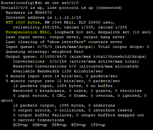
이더넷 최대 MTU값 = 1518바이트
-
라우터에서 캡슐화 종류를 설정해줄 수 있다. (
HDLC, Frame Relay, PPP)
HDLC, Frame Relay, PPP중인증기능이 있는 프로토콜은 PPP이다.
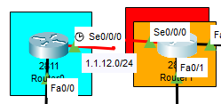
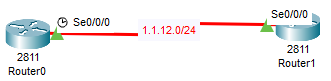
- 위에서 언급한 캡슐화는 라우터간 연결(Point to Point)이 서로 같은 종류여야 통신 가능하다.
[PPP]
PPP는 WAN에서 사용하는 통신 프로토콜(이외에도 HDLC, ATM, Frame Relay 존재)이며
PPP의 인증방식에는 평문으로 전송하는 PAP방식, 암호화하여 전송하는 CHAP방식이 있다.
[PPP사용]
(R0)
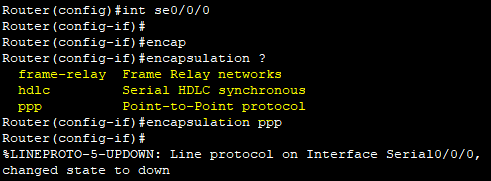
Router(config)#int se0/0/0
Router(config-if)#encapsulation ppp
(R1)
Router(config)#int se0/0/0
Router(config-if)#encapsulation ppp
정리)
여기까지 했다면 R0과 R1은 통신 가능한 상태
-Point to Point로써 연결은 서로 같은 프로토콜을 사용해야 가능하다.
[PPP 인증 방식]
[1. PAP(평문인증)]
(R0)
보안은 Default를 싫어하므로 호스트네임부터 바꿔주자.
Router(config)#hostname R0유저네임을 생성하는 이유 : 내가 필요한것보다 상대방이 나에게 접속 할 수 있게 아이디를 만들어 주는것.
R0(config)#username R1 password 1234그 후 pap 방식으로 설정하기 위해 해당 명령어를 추가 해주어야한다.
R0(config)#int se0/0/0
R0(config-if)#encapsulation ppp
R0(config-if)#ppp authentication pap
R0(config-if)#ppp pap sent-username R0 password 1234
(R1)도 R0과 동일하게 설정해준다.
Router(config)#hostname R1
R1(config)#username R0 password 1234
R1(config)#int se0/0/0
R1(config-if)#ppp authentication pap
R1(config-if)#ppp pap sent-username R1 password 1234
[2. CHAP(암호화인증)]
해당 방식도 PAP방식과 동일하게 실행하면 된다.
Router(config)#hostname R0
R0(config)#username R1 password 1234
R0(config)#int se0/0/0
R0(config-if)#encapsulation ppp
그 후 간단하게 해당 명령어 실행하면 설정된다.
R0(config-if)#ppp authentication chap(R1)도 R0과 동일한 방법으로 설정
Router(config)#hostname R1
R1(config)#username R0 password 1234
R1(config)#int se0/0/0
R0(config-if)#encapsulation ppp
R1(config-if)#ppp authentication chap
주의!!!)
1. 서로 CHAP모드로 연결된 R0와 R1에는 서로 상대방의 유저네임을 가져야 통신이 가능하다.
2. PAP와 CHAP모드 둘 다 상대측 유저네임을 가져야한다.
- 두 모드의 차이점은 sent-name을 이용하여 수동으로 보내거나 간편하게 보내는 차이
[실습]
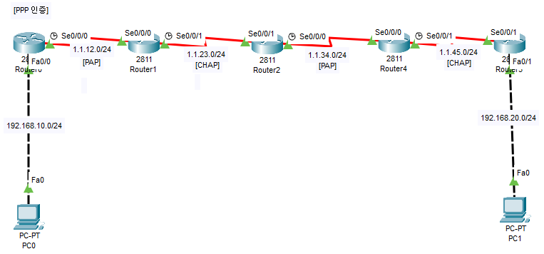
- PC0과 PC1의 연결이 목적
- R0-R1/R2-R3은
PAP모드, R1-R2/R3-R4은CHAP모드- point to point로 연결이 됐다면
ip route로 라우팅해주기
[SSH원격접속]
[1. 라우터의 SSH/원격접속]
Router(config)#hostname R1
R1(config)#username cisco password 1234
R1(config)#ip domain-name [cisco.co.kr](http://cisco.co.kr/)

R1(config)#crypto key generate rsa
How many bits in the modulus [512]: 1024
% Generating 1024 bit RSA keys, keys will be non-exportable...[OK]

R1(config)#line vty 0 4
R1(config-line)#login local
R1(config-line)#transport input ssh
<enable 모드 패스워드 생성>
R1(config)#enable password 1234<클라이언트에서 접속>
C:\>ssh -l cisco 192.168.20.1[2. L3 스위치의 SSH/원격접속]
L3스위치의 설정법은 라우터와 동일하다.
MEGA-L3SWITCH(config)#hostname L3SW
L3SW(config)#username cisco password 1234
L3SW(config)#ip domain-name cisco.co.kr

L3SW(config)#crypto key generate rsa
How many bits in the modulus [512]: 1024
% Generating 1024 bit RSA keys, keys will be non-exportable...[OK]

L3SW(config)#line vty 0 4
L3SW(config-line)#login local
L3SW(config-line)#transport input ssh

L3SW(config)#enable password 1234
[3. L2 스위치의 SSH/원격접속]
- L2 스위치는 라우터, L3스위치와 다르게 기존 모드에서 주소를 넣지 못한다.
하지만 L2 스위치에는 유지보수 차원에서 VLAN 1이라는 물리적인 인터페이스가 존재한다.
해당 명령어를 통해 통신이 가능한 3요소(ip, s/m, g/w)를 추가해준다.
MEGA-SWITCH(config)#int vl 1
MEGA-SWITCH(config-if)#ip address 192.168.30.100 255.255.255.0
MEGA-SWITCH(config-if)#no shutdown
MEGA-SWITCH(config)#ip default-gateway 192.168.30.1
여기까지 VLAN1에 대해 주소 설정을 해주었다면 이후는 라우터와 L3 스위치와 동일하다.
MEGA-SWITCH(config)#hostname SW1
SW1(config)#username cisco password 1234
SW1(config)#ip domain-name cisco.co.kr

SW1(config)#crypto key generate rsa
How many bits in the modulus [512]: 1024
% Generating 1024 bit RSA keys, keys will be non-exportable...[OK]- 여기까지 설정은 준비단계이며 다음 명령어에서 적용을 시켜주어야한다.
이러한 설정들을 적용시킬 장소는 LINE이고
SW1(config)#line vty 0 4로그인 할때 설정한 것을 적용시키며
SW1(config-line)#login local이를 ssh 방식으로 받아 들이겠다라고 설정한다.
SW1(config-line)#transport input ssh[Frame Relay]
- 단순히 뜻만 보면? -> 프레임을 릴레이한다.
LAN간 또는 광역통신망(WAN)내 단말 지점 간의 비용-효율적인 데이터의 전송을 위해 고안되었다.- 망의 종류는
1. 공중 전화망,2. 공중 데이터 망,3. 전용회선으로 구성되어있다. 1. 공중 전화망은a. 회선교환,b. 패킷 교환,c. 메시지교환방식으로 나뉜다.2. 공중 데이터 망(ATM)은a. 데이터그램 방식과b. 가상회선 방식으로 구성된다.
패킷 교환방식
- 회선률이 좋지만 속도가 느리다.
- 이러한 속도 이슈를 해결하기 위해 나온것이
Frame Relay - 경로상 노드들이 일일히 오류 체크를 하는것이 아닌 처음과 끝에서만 체크하는것
공중 데이터 망(ATM)
a. 데이터그램에는 UTP,b. 가상회선 방식(PVC)에는 TCP와 Frame Relay 포함
cf) PVC를 처음 적용한 기술이 ADSL
[Frame Relay Switch]
- 기존 PPP 방식은
라우터-라우터간의 통신이 가능하다 - 하지만 F/R 방식은
라우터-F/R스위치-라우터로 구성해야 통신이 가능하다.
라우터-라우터불가능 - 해당 방식에서 식별자는
DLCI(Data Link Control Identifier)이다.
즉,라우터<-(시리얼포트)->DLCI<-(시리얼포트)->스위치방식으로 통신 - 자동 맵핑(Reverse ARP)과 수동맵핑
F/R 스위치가 완벽한 메쉬망이 아니라서 예외되는 라우터 등장->자동 맵핑이 아닌 수동 맵핑 사용
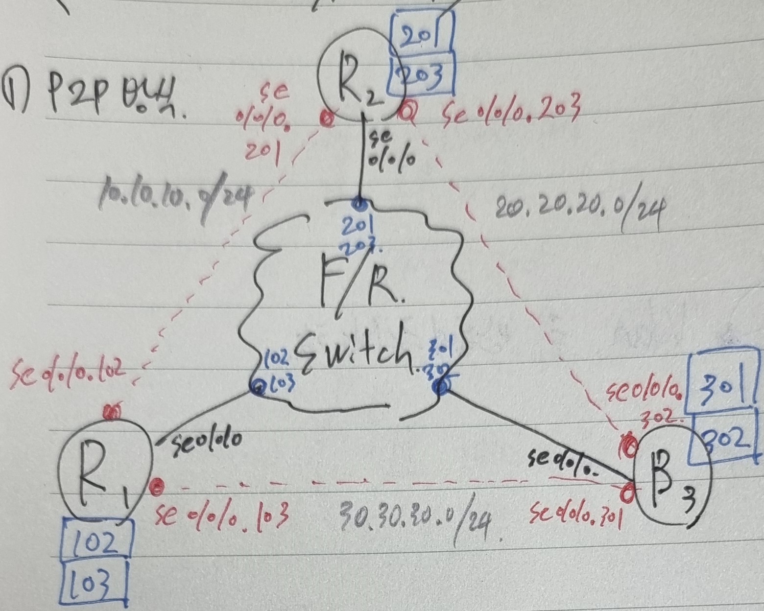
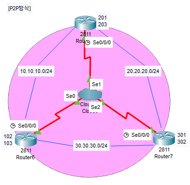
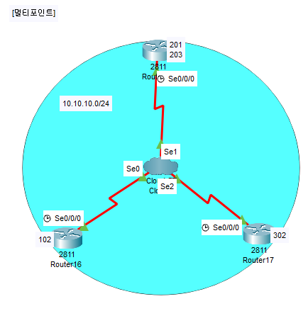
[Frame Relay 구성방식]
- F/R 스위치는 클라우드 안에 존재
라우터-(시리얼포트)-{F/R스위치}-(시리얼포트)-라우터 - 서브 인터페이스를 생성하는 방식
ex)Se0/0/0.201-Se0/0/0.102,Se0/0/0.203-Se0/0/0.302,Se0/0/0.103-Se0/0/0.301 - IP 또한 서브 인터페이스에 따라 다르게 할당해줘야한다.
- 포인트 투 포인트(point to point) 방식
(R1)
<R1-R2라우터 설정>
Router(config)#int se0/0/0
Router(config-if)#encapsulation frame-relay
Router(config)#int se0/0/0.102 point
Router(config-subif)#ip address 10.10.10.1 255.255.255.0
Router(config-subif)#frame-relay interface-dlci 102<R1-R3라우터 설정>
Router(config-subif)#int se0/0/0.103 point
Router(config-subif)#ip add 30.30.30.1 255.255.255.0
Router(config-subif)#frame-relay interface-dlci 103(R2)
<R2-R1라우터 설정>
Router(config)#int se0/0/0
Router(config-if)#encapsulation frame-relay
Router(config-if)#int se0/0/0.201 point
Router(config-subif)#ip add 10.10.10.2 255.255.255.0
Router(config-subif)#frame-relay interface-dlci 201<R2-R3라우터 설정>
Router(config-subif)#int se0/0/0.203 point
Router(config-subif)#ip add 20.20.20.2 255.255.255.0
Router(config-subif)#frame-relay interface-dlci 203(R3)
<R3-R1라우터 설정>
Router(config)#int se0/0/0
Router(config-if)#encapsulation frame-relay
Router(config-if)#int se0/0/0.301 point
Router(config-subif)#ip address 30.30.30.2 255.255.255.0
Router(config-subif)#frame-relay interface-dlci 301<R3-R2라우터 설정>
Router(config-subif)#int se0/0/0.302 point
Router(config-subif)#ip add 20.20.20.1 255.255.255.0
Router(config-subif)#frame-relay interface-dlci 302(중앙 클라우드에서의 맵핑)
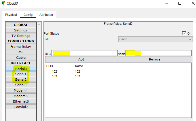
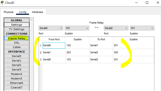
- 인터페이스 탭에서
DLCI값을 를 추가해준 후 Frame Relay 탭에서F/R 포트를 서로 맵핑해준다.
- 멀티 포인트(Multi Point) 방식

(R1)
Router(config)#int se0/0/0
Router(config-if)#no sh
Router(config-if)#en fr

Router(config-if)#ip add 10.10.10.1 255.255.255.0
Router(config-if)#frame-relay map ip 10.10.10.2 102 broadcast
Router(config-if)#frame-relay map ip 10.10.10.3 102 broadcast
(R3)
Router(config)#int se0/0/0
Router(config-if)#no sh
Router(config-if)#en fr

Router(config-if)#ip add 10.10.10.3 255.255.255.0
Router(config-if)#fr map ip 10.10.10.1 302 broadcast
Router(config-if)#fr map ip 10.10.10.2 302 broadcast
(R2)
Router(config)#int se0/0/0
Router(config-if)#no sh
Router(config-if)#en fr

Router(config-if)#int se0/0/0.123 multi
Router(config-subif)#ip add 10.10.10.2 255.255.255.0
Router(config-subif)#fr map ip 10.10.10.1 201 broadcast
Router(config-subif)#fr map ip 10.10.10.3 203 broadcast
정리)
1. R1과 R3에서frame-relay map ip (상대편IP주소) (DLCI) broadcast명령어를 이용하여 중계 라우터(R2)로 주소 설정(DLCI가 102/302)
2. 중계라우터에int se0/0/0.123 multi명령어를 이용하여 서브 인터페이스 생성
3. 중계 라우터에선 R1, R3로 각각frame-relay map ip명령어 쏴주기
(중앙 클라우드에서의 맵핑)

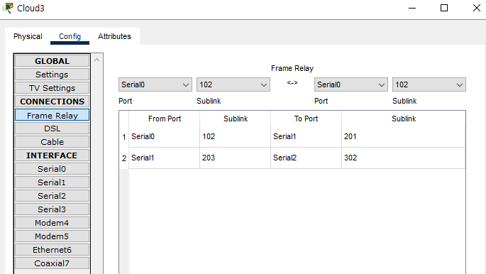
- P2P 방식과 동일하게 인터페이스 탭에서
DLCI값을 를 추가해준 후 Frame Relay 탭에서F/R 포트를 서로 맵핑해준다. - P2P 방식과 차이점은 일일히 맵핑해주는 것이 아닌 중계 라우터외의 라우터들은 한번씩만 추가해주면 된다.
