8bit Adder
기존에 설계한 4bit Adder로 구조적모델링을 통해 8bit Adder를 설계한다.
module Adder_8bit (
    input [7:0] a,
    input [7:0] b,
    input cin,
    output [7:0] sum,
    output co
);
    wire w_carry0;

    Adder_4bit U_4bit_Adder0 (
        .a  (a[3:0]),
        .b  (b[3:0]),
        .cin(cin),
        .sum(sum[3:0]),
        .co (w_carry0)
    );

    Adder_4bit U_4bit_Adder1 (
        .a  (a[7:4]),
        .b  (b[7:4]),
        .cin(w_carry0),
        .sum(sum[7:4]),
        .co (co)
    );

endmodule
Simulation
이번에는 System Verilog를 이용해 변수를 랜덤으로 돌려 시뮬레이션을 해보겠다.
class transaction; // 변수 a,b를 transaction으로 캡슐화, 묶어버림
    rand logic [7:0] a;
    rand logic [7:0] b;
endclass  //transaction

module tb_adder ();
    // 주소를 담을 수 있는 변수다.
    transaction trans;  // class의 변수 만들기, class이름에 변수처럼 선언하면 handler라 한다.

    logic [7:0] a, b, sum;
    logic co;

    Adder_8bit dut (
        .a  (a),
        .b  (b),
        .cin(1'b0),
        .sum(sum),
        .co (co)
    );

    initial begin
        trans = new(); // 생성자, 메모리에 실체화된다.
        repeat (10000) begin // 반복
            trans.randomize(); // 랜더마이즈를 시작하면 trans안의 rand변수들을 랜덤하게 부여, data 생성
            a = trans.a; // dut에 data전송
            b = trans.b; // dut에 data전송
            #10;
            $display("%t : a(%d) + b(%d) = sum(%d)", $time, trans.a, trans.b, {co, sum});
            if ((trans.a + trans.b) == {co, sum}) $display("passed!"); // 생성 data와 출력 data를 비교해서 pass, fail판단
            else $display("failed!");
        end
    end
endmodule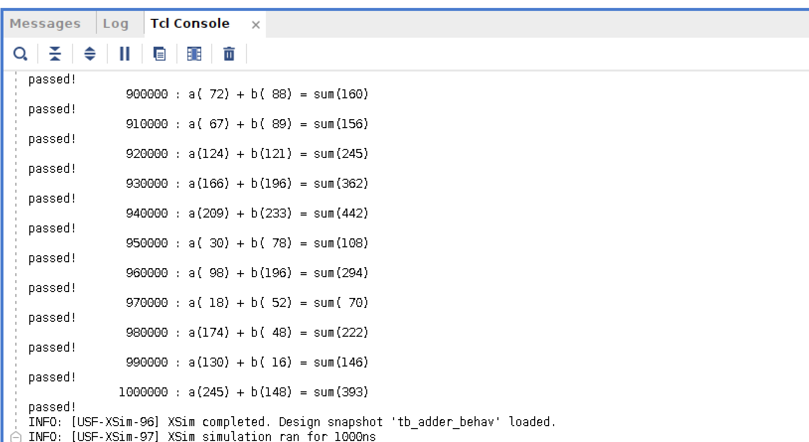
테스트 결과는 console에서 확인한다.
FND Controller
Adder 결과를 FND에 Display하기 위해서는 Adder출력을 FND에 맞게 변형하여 출력해야한다.
FND(Flexible Numeric Display) 이론
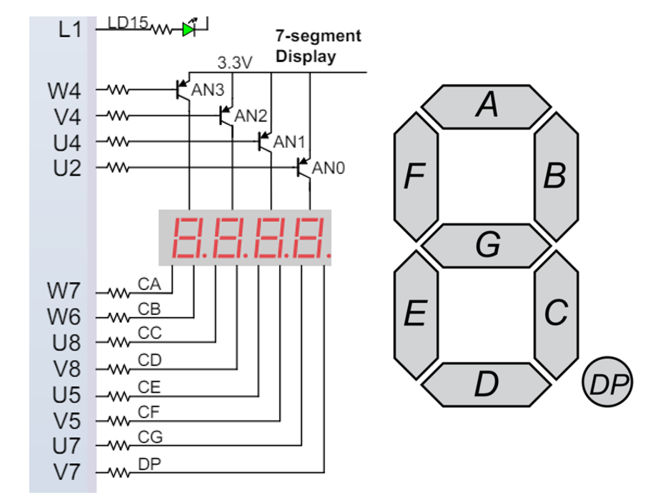
FND는 LED로 숫자 혹은 문자를 표시하며 7-Segment라고도 부른다.
Anode type : Common단자에 전원을 입력 후 원하는 단자에 LOW 신호를 인가하여 LED를 ON시키는 방식
Cathode type: Common단자에 GND를 연결하고 원하는 단자에는 HIGH 신호를 인가하여 LED를 ON시키는 방식
basys3는 Anode type의 FND를 사용하고 있다.
Common단자에 pnp tr을 사용하므로 base에 low를 주면 해당 digit이 on된다.
BCD to Segment Decoder
숫자를 FND로 표현할 수 있게 각 숫자에 맞게 mapping해준다. BCD를 FND로 변환한다고 표현했지만 코드는 4bit의 최대 수인 1111 즉, Hex까지 표현가능하도록 만들었다.
module BCDtoSEG (  // 숫자를 segment모양으로 출력
    input [3:0] bcd,
    output reg [7:0] seg
);
	// bcd를 always가 계속 감시하다가 변화가 감지되면 begin문을 시작
    always @(bcd) begin  // decoder
        case (bcd)
            4'h0: seg = 8'hc0;
            4'h1: seg = 8'hf9;
            4'h2: seg = 8'ha4;
            4'h3: seg = 8'hb0;
            4'h4: seg = 8'h99;
            4'h5: seg = 8'h92;
            4'h6: seg = 8'h82;
            4'h7: seg = 8'hf8;
            4'h8: seg = 8'h80;
            4'h9: seg = 8'h90;
            4'ha: seg = 8'h88;
            4'hb: seg = 8'h83;
            4'hc: seg = 8'hc6;
            4'hd: seg = 8'ha1;
            4'he: seg = 8'h86;
            4'hf: seg = 8'h8e;
            default: seg = 8'hff;
        endcase
    end
endmodule
Digit Splitter & MUX
만약 123이라는 Adder의 결과를 FND에 출력하려면 각 자리수에 해당하는 숫자를 FND에 해당 자리에 출력해야한다.
Adder의 결과를 FND자리수에 맞게 1, 10, 100, 1000의 자리로 출력을 구분해주는 회로다.
module digitSplitter (
    input [13:0] i_digit,  // 0부터 9999까지 나타내는 bit수
    output [3:0] o_digit_1,
    output [3:0] o_digit_10,
    output [3:0] o_digit_100,
    output [3:0] o_digit_1000
);
    assign o_digit_1    = i_digit % 10;
    assign o_digit_10   = i_digit / 10 % 10;
    assign o_digit_100  = i_digit / 100 % 10;
    assign o_digit_1000 = i_digit / 1000 % 10;
endmodule
splitter에 의해 분리된 출력을 하나만 선택하는 회로 : MUX
module mux (
    input      [1:0] sel, // 4x1Mux는 2bit의 select신호 필요
    input      [3:0] x0,
    input      [3:0] x1,
    input      [3:0] x2,
    input      [3:0] x3,
    output reg [3:0] y
);

    always @(*) begin  // '*' is all input
        case (sel)
            2'b00:   y = x0;
            2'b01:   y = x1;
            2'b10:   y = x2;
            2'b11:   y = x3;
            default: y = x0;
        endcase
    end

endmodule
2x4 Decoder
FND의 Common단자를 제어하는 회로다. MUX와 마찬가지로 Select신호에 의해 출력이 결정된다.
00 : 1의 자리
01 : 10의 자리
10 : 100의 자리
11 : 1000의 자리
| x0 | x1 | y3 | y2 | y1 | y0 |
|---|---|---|---|---|---|
| 0 | 0 | 1 | 1 | 1 | 0 |
| 0 | 1 | 1 | 1 | 0 | 1 |
| 1 | 0 | 1 | 0 | 1 | 1 |
| 1 | 1 | 0 | 1 | 1 | 1 |
common단자는 0(Low)에서 on이 된다.
module decoder (
    input [1:0] x,
    output reg [3:0] y
);

    always @(x) begin
        case (x)
            2'b00:   y = 4'b1110;
            2'b01:   y = 4'b1101;
            2'b10:   y = 4'b1011;
            2'b11:   y = 4'b0111;
            default: y = 4'b1111;
        endcase
    end
endmodule
FND Controller
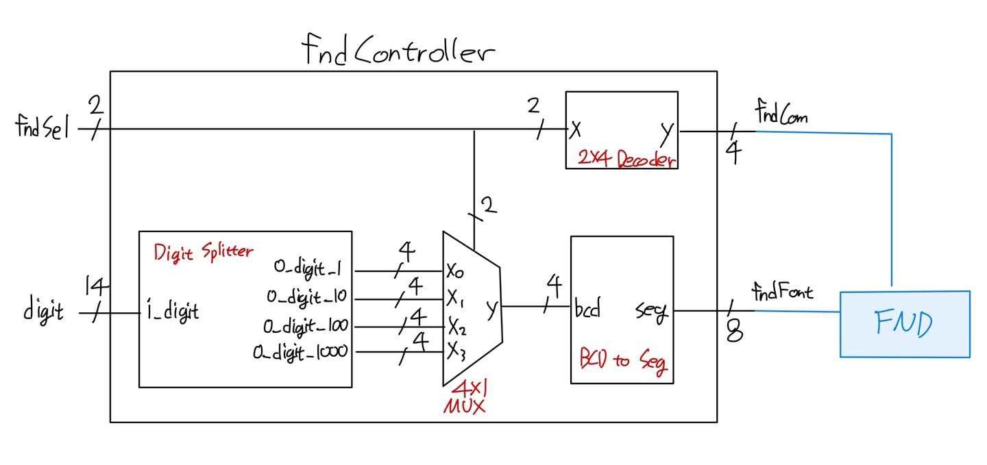
module fndController (
    input  [ 1:0] fndSel,
    input  [13:0] digit,
    output [ 7:0] fndFont,
    output [ 3:0] fndCom
);
    wire [3:0] w_digit_1, w_digit_10, w_digit_100, w_digit_1000;
    wire [3:0] w_digit;

    decoder U_Decoder_2x4 (
        .x(fndSel),
        .y(fndCom)
    );

    digitSplitter U_DigitSplitter (
        .i_digit     (digit),
        .o_digit_1   (w_digit_1),
        .o_digit_10  (w_digit_10),
        .o_digit_100 (w_digit_100),
        .o_digit_1000(w_digit_1000)
    );

    mux U_Mux_4x1 (
        .sel(fndSel),
        .x0 (w_digit_1),
        .x1 (w_digit_10),
        .x2 (w_digit_100),
        .x3 (w_digit_1000),
        .y  (w_digit)
    );

    BCDtoSEG U_BcdToSeg (
        .bcd(w_digit),
        .seg(fndFont)
    );

endmodule
Display Core(8bit Adder) on FND
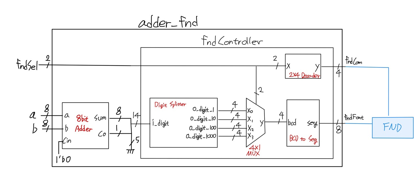
module adder_fnd (
    input  [1:0] fndSel,
    input  [7:0] a,
    input  [7:0] b,
    output [3:0] fndCom,
    output [7:0] fndFont
);
    wire [7:0] w_sum;
    wire w_carry;

    Adder_8bit U_Adder (
        .a  (a),
        .b  (b),
        .cin(1'b0), // adder의 처음carry는 0
        .sum(w_sum),
        .co (w_carry)
    );

    fndController U_FndController (
        .fndSel (fndSel),
         // {}는 bit결합연산자, 오른쪽 LSB, 왼쪽 MSB, 14bit를 맞추기 위해 5bit를 0으로 채움
        .digit  ({5'b0, w_carry, w_sum}),
        .fndFont(fndFont),
        .fndCom (fndCom)
    );

endmodule
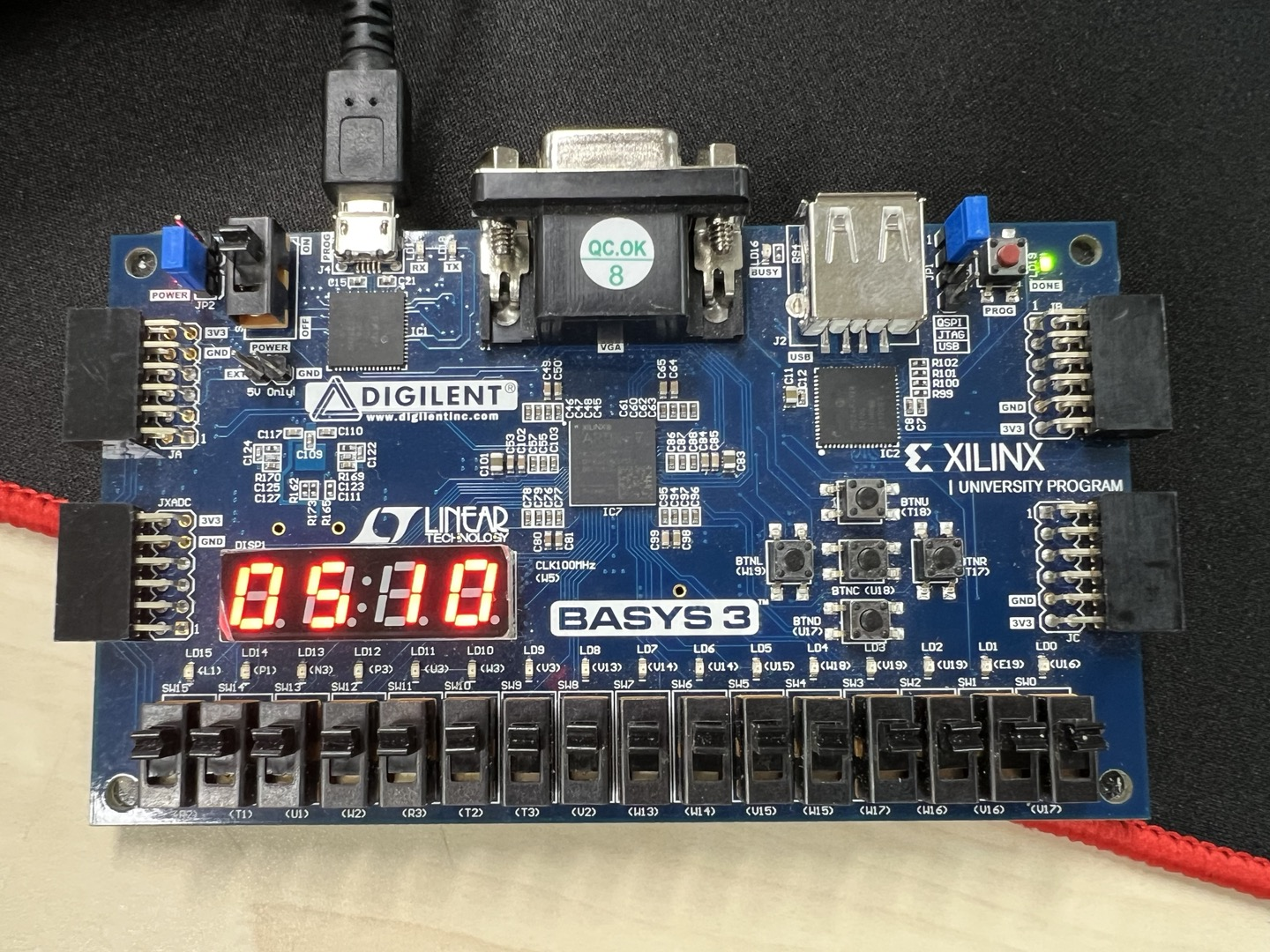
보드 하단의 스위치를 모두 1로 만들어 Adder 결과가 510이 되고, 버튼을 통해 FND 자리수를 변경해 확인할 수 있다.
그러나 Common을 직접 변경하므로 FND의 모든 자리를 한번에 나타나지 않는다.
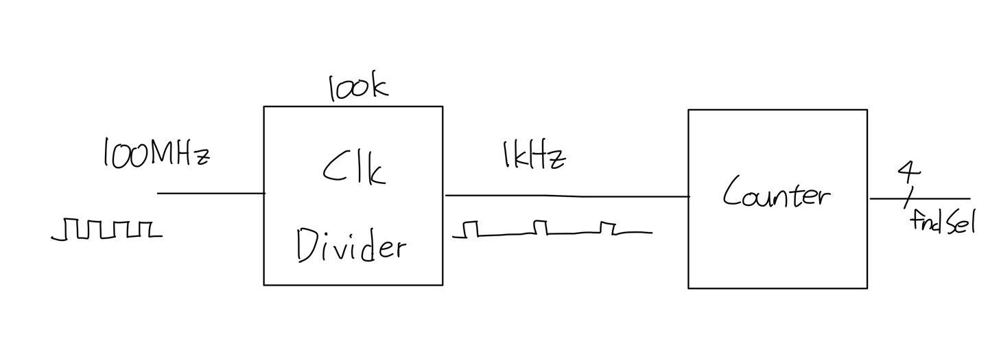
Counter
동시에 표현하기 위해 FND의 각 자리수를 순서대로 빠르게 실행시키면 잔상효과에 의해 모든 자리를 볼 수 있다.
basys3의 clock을 통해 fndSel을 계속해서 빠르게 변경할 수 있다.
Counter는 clock을 단순히 count하는 회로다.
basys3는 100MHz의 clock freq를 가진다.
그러나 너무 빠른 clock은 FND확인이 불가능하므로 Prescaling하여 clock을 분주해준다.
Counter
clk의 rising edge에 맞춰 count를 하나씩 증가시키는 회로다.
module counter #(parameter MAX_COUNT = 4)( // parameter는 define과 유사기능, default : 4
    input        clk,
    output [$clog2(MAX_COUNT)-1:0] count // fndSel 2bit
);
    reg [$clog2(MAX_COUNT)-1:0] counter = 0; // output 기본적으로 wire type이므로 저장가능한 변수 선언

    assign count = counter; // 연결

    always @(posedge clk) begin // clk의 rising edge의 변화를 감지
        if (counter == MAX_COUNT - 1) begin // counter값이 최대면 0으로 초기화
            counter <= 0;
        end else begin
            counter <= counter + 1;
        end
    end
endmodule
Clock Divider
원리는 Counter와 동일하며 출력값이 Count가 아닌 1과 0이다.
아래 코드는 한 clk만 1이고 나머지는 0으로 만드는 duty비를 가지고 있다.
module clkDiv #(parameter MAX_COUNT = 100)(
    input  clk,
    output o_clk
);
    reg [$clog2(MAX_COUNT)-1:0] counter = 0;
    reg r_tick = 0;

    assign o_clk = r_tick;

    always @(posedge clk) begin
        if (counter == (MAX_COUNT - 1)) begin
            counter <= 0;
            r_tick  <= 1'b1;
        end else begin
            counter <= counter + 1;
            r_tick  <= 1'b0;
        end
    end
endmodule
$clog2(MAX_COUNT)
괄호 안의 값을 밑이 2인 log를 취한 후 절상하는 함수다.
즉, 괄호 안에 십진수를 쓰면 함수의 결과는 십진수를 표현할 수 있는 최소bit수가 나온다.