LED On/Off
LED_FSM
LED의 On/Off동작을 FSM을 이용해 코딩한다.
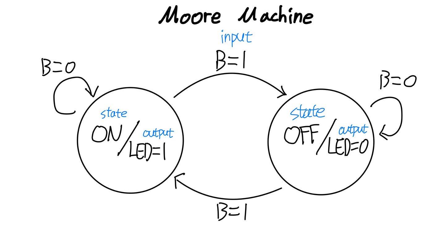
버튼이 눌리면 LED가 전환(on/off)된다.
module led_FSM (
    input clk,
    input reset,
    input button,
    output reg led
);
	// State는 Parameter를 통해 표현한다.
    parameter LED_OFF = 1'b0, LED_ON = 1'b1;

    reg state, state_next; // 현재상태, 다음상태

    // state register, 현재상태 저장
    always @(posedge clk, posedge reset) begin
        if (reset) begin
            state <= LED_OFF; // 초기화는 Off상태
        end else begin
            state <= state_next; // 다음상태가 현재상태를 결정
        end
    end

    // Next State Combinational Logic Circuit
    always @(state, button) begin
        state_next = state;
        case (state) // 현재상태와 입력이 다음상태를 결정
            LED_OFF: begin
                if (button == 1'b1) state_next = LED_ON;
                else state_next = state;
            end
            LED_ON: begin
                if (button == 1'b1) state_next = LED_OFF;
                else state_next = state;
            end
        endcase
    end

    // Output Combinational Logic Circuit (Moore Machine)
    always @(state) begin
        led = 1'b0;
        case (state) // Moore에서의 출력은 현재상태가 결정
            LED_OFF: led = 1'b0;
            LED_ON:  led = 1'b1;
        endcase
    end
// Output Combinational Logic Circuit (Mealy Machine)
always @(state, button) begin
led = 1'b0;
case (state) // Mealy에서의 출력은 현재상태와 입력이 결정
LED_OFF: begin
if (button == 1'b1) led = 1'b1;
else led = 1'b0;
end
LED_ON: begin
if (button == 1'b1) led = 1'b0;
else led = 1'b1;
end
endcase
end
endmoduleButton
모든 버튼 혹은 스위치는 Chattering현상이 존재한다.
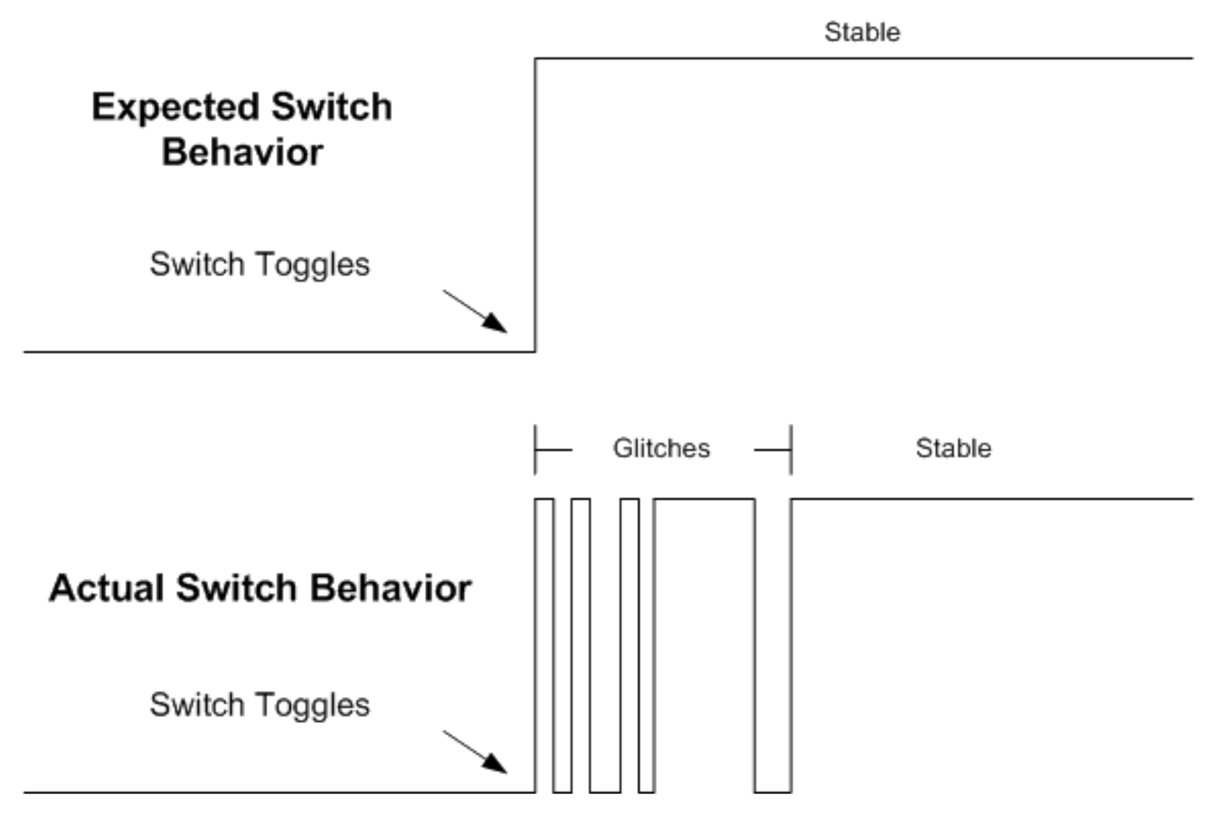
Chattering현상으로 인해 하드웨어에 원하지 않는 동작이 발생하기 때문에 이를 필터링해주는 debouncer가 필요하다.
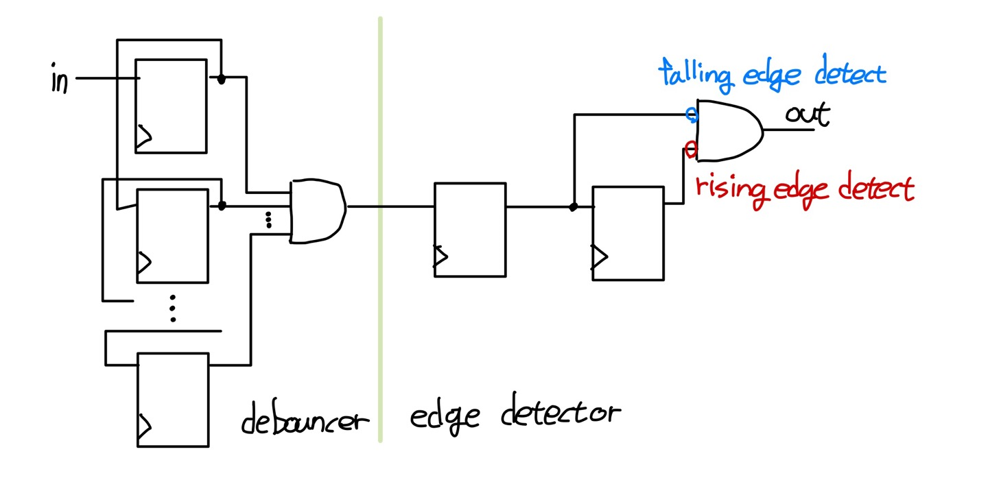
shift register를 통해 나온 모든 출력(parallel output)을 AND하고 그 결과를 출력으로 사용하면서 parallel output중에 하나라도 0이 포함되면 chattering으로 판단한다.
debouncer의 결과와 2개 DFF을 직렬로 연결하고 DFF의 출력을 output logic을 통해 rising edge를 detect할지 falling edge를 detect할지 정할 수 있다.
module button (
input clk,
input in,
output out
);
localparam N = 64; // shift register의 갯수
wire w_debounce_out;
reg [1:0] dff_reg, dff_next;
reg [N-1 : 0] q_reg, q_next;
// debounce circuit
always @(*) begin
q_next = {q_reg[N-2:0], in};
end
always @(posedge clk) begin
q_reg <= q_next;
end
assign w_debounce_out = &q_reg;
// dff edge detect
always @(*) begin
dff_next[0] = w_debounce_out;
dff_next[1] = dff_reg[0];
end
always @(posedge clk) begin
dff_reg <= dff_next;
end
// output logic
assign out = ~dff_reg[0] & dff_reg[1];
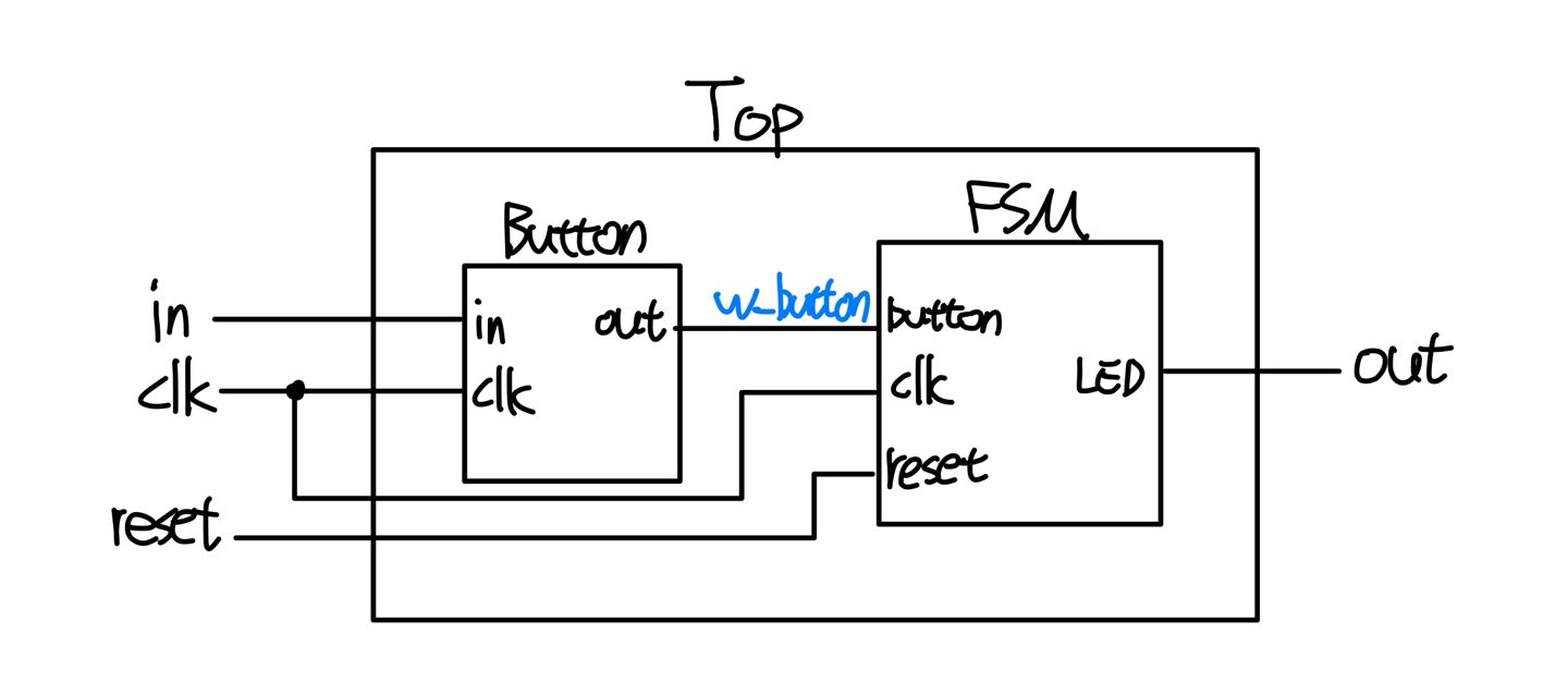
endmoduleLED 출력
LED FSM모듈과 Button모듈을 하나의 Top모듈로 합쳐 System을 구현한다.
Counter
Control Unit
control unit은 전체 system에 제어를 담당하는 회로다.
button을 통해 입력된 신호를 현재상태와 함께 판단하여 다른 장치들에게 명령을 내린다.
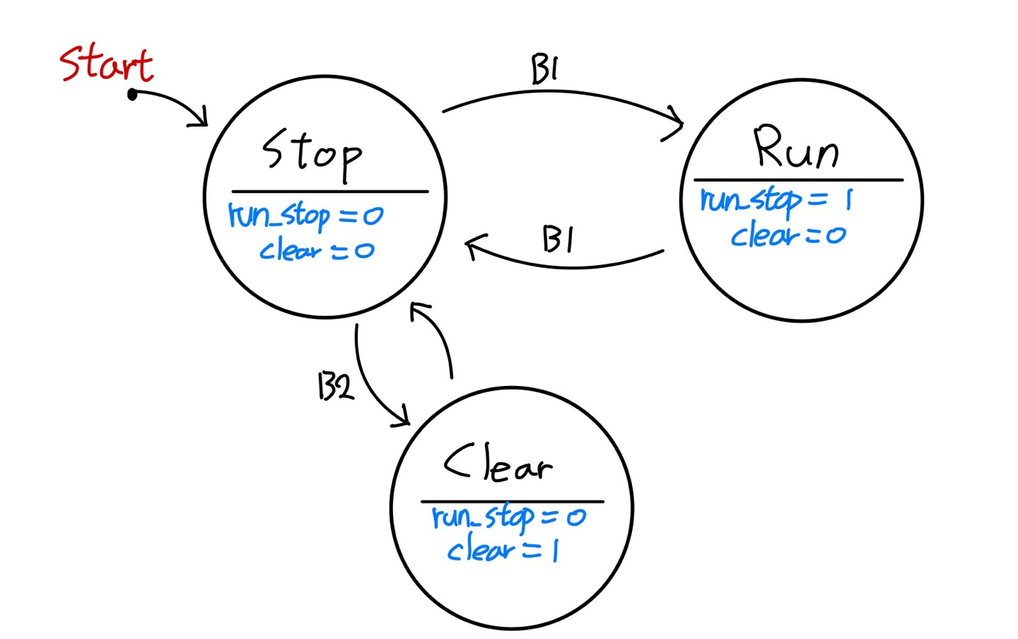
FSM을 토대로 코드를 만든다.
module control_unit(
    input clk,
    input reset,
    input btn_run_stop,
    input btn_clear,
    output run_stop,
    output clear,
    output [2:0] led
    );

    parameter STOP = 2'd0, RUN = 2'd1, CLEAR = 2'd2;
    reg [1:0] state, state_next;
    reg run_stop_reg, run_stop_next, clear_reg, clear_next;

    assign run_stop = run_stop_reg;
    assign clear = clear_reg;

    // state register
    always @(posedge clk, posedge reset) begin
        if (reset) begin
            state <= STOP;
            run_stop_reg <= 1'b0;
            clear_reg <= 1'b0;
        end else begin
            state <= state_next;
            run_stop_reg <= run_stop_next;
            clear_reg <= clear_next;
        end
    end

    // next state combinational logic
    always @(*) begin
        state_next = state;
        case (state)
            STOP: begin
                if (btn_run_stop) state_next = RUN;
                else if (btn_clear) state_next = CLEAR;
                else state_next = STOP;
            end
            RUN: begin
                if (btn_run_stop) state_next = STOP;
                else state_next = RUN;
            end
            CLEAR: begin
                state_next = STOP;
            end
        endcase
    end

    // output combinational logic
    assign led[0] = (state == STOP) ? 1'b1 : 1'b0; // stop led
    assign led[1] = (state == RUN) ? 1'b1 : 1'b0; // run led
    assign led[2] = (state == CLEAR) ? 1'b1 : 1'b0; // clear led

    always @(*) begin
        run_stop_next = 1'b0; // case문에 없으면 default로 저장
        clear_next = 1'b0; // case문에 변수에 대한 지정이 없으면 래치가 생길 수도 있음
        case (state)
            STOP: begin
                run_stop_next = 1'b0;
            end
            RUN: begin
                run_stop_next = 1'b1;
            end
            CLEAR: begin
                clear_next = 1'b1;
            end
        endcase
    end

endmodule
UpCounter
module up_counter(
    input clk,
    input reset,
    input tick,
    input run_stop,
    input clear,
    output [13:0] count
    );

    reg [13:0] counter_reg, counter_next;

	// output logic
    assign count = counter_reg;

	// state register
    always @(posedge clk, posedge reset) begin
        if (reset) begin
            counter_reg <= 0;
        end else begin
            counter_reg <= counter_next;
        end
    end

	// next state logic
    always @(*) begin
        counter_next = counter_reg;
        if (tick && run_stop) begin
            if (counter_reg == 9999) begin
                counter_next = 0;
            end else begin
                counter_next = counter_reg + 1;
            end
        end
        else if (clear) begin
            counter_next = 0;
        end
    end

endmodule
tick && run_stop을 통해 run상태에서 tick신호에 맞춰 count가 증가하게 된다.
또한 count가 max거나 clear신호가 입력되면 count값은 초기화된다.
Top
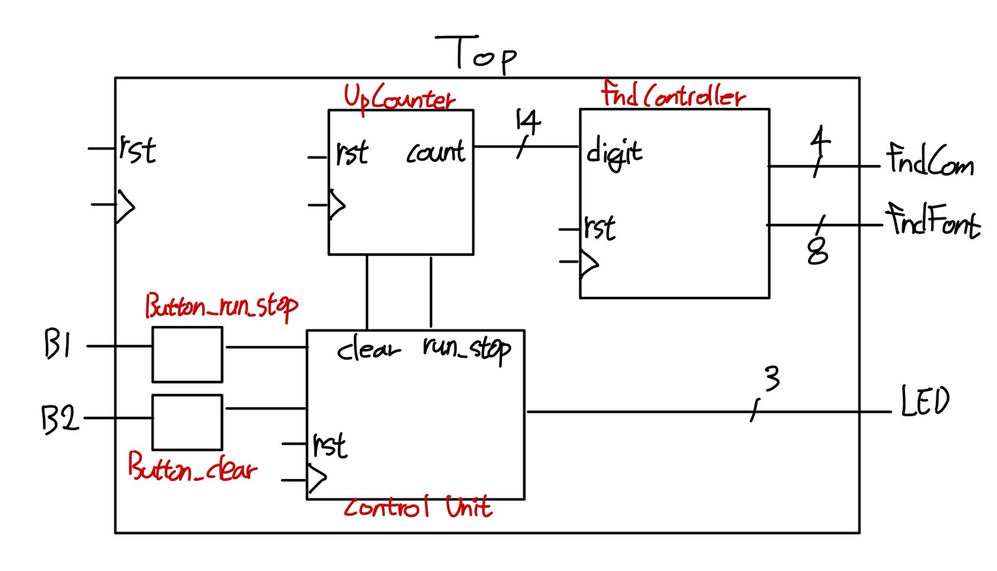
모든 모듈을 Top으로 합친다.
module top (
    input clk,
    input reset,
    input btn_run_stop,
    input btn_clear,
    output [3:0] fndCom,
    output [7:0] fndFont,
    output [2:0] led
);

    wire w_clk_10hz;
    wire w_run_stop, w_clear;
    wire [13:0] w_digit;

    clkDiv #(
        .MAX_COUNT(10_000_000)
    ) U_ClkDiv (
        .clk  (clk),
        .reset(reset),
        .o_clk(w_clk_10hz)
    );

    up_counter U_UpCounter (
        .clk(clk),
        .reset(reset),
        .tick(w_clk_10hz),
        .run_stop(w_run_stop),
        .clear(w_clear),
        .count(w_digit)
    );

    fndController U_FndController (
        .clk(clk),
        .reset(reset),
        .digit(w_digit),
        .fndFont(fndFont),
        .fndCom(fndCom)
    );

    wire w_btn_run_stop, w_btn_clear;

    button U_btn_RunStop (
        .clk(clk),
        .in (btn_run_stop),
        .out(w_btn_run_stop)
    );

    button U_btn_Clear (
        .clk(clk),
        .in (btn_clear),
        .out(w_btn_clear)
    );

    control_unit U_control_unit (
        .clk(clk),
        .reset(reset),
        .btn_run_stop(w_btn_run_stop),
        .btn_clear(w_btn_clear),
        .run_stop(w_run_stop),
        .clear(w_clear),
        .led(led)
    );

    ila_0 U_ILA (
        .clk(clk),  // input wire clk
        .probe0(w_btn_run_stop),  // input wire [0:0]  probe0
        .probe1(w_btn_clear),  // input wire [0:0]  probe1
        .probe2(w_run_stop),  // input wire [0:0]  probe2
        .probe3(w_clear),  // input wire [0:0]  probe3
        .probe4(w_digit),  // input wire [13:0]  probe4
        .probe5(fndCom),   // input wire [3:0]  probe5
        .probe6(w_clk_10hz) // input wire [0:0]  probe6
    );

endmodule
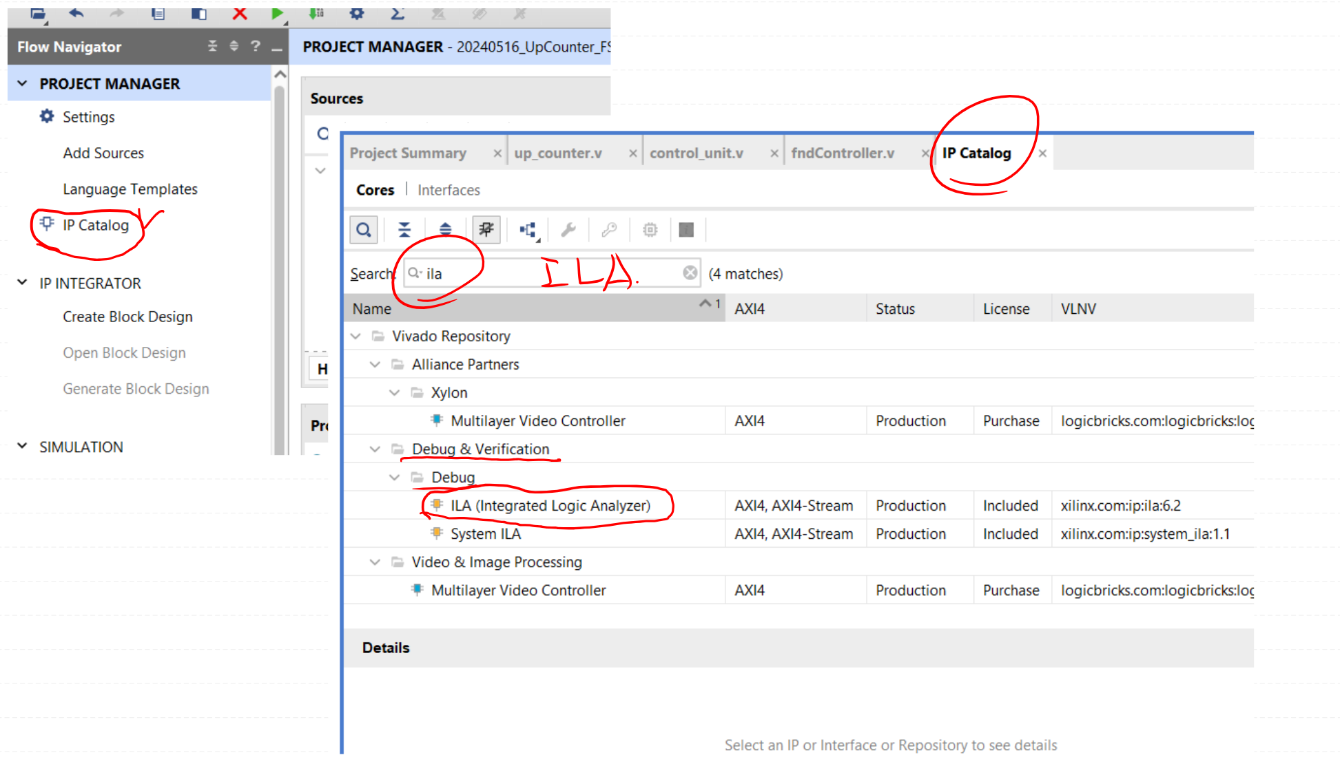
ILA
소프트웨어 프로그램에서 data의 변화를 관찰하기 위해 메모리의 데이터를 확인하는 debug를 이용한다. verilog에서도 이런 debug를 활용하기 위해 Xilinx에서 제공해주는 IP인 ILA를 통해 회로에서 data가 이동하는 것을 관찰하고, 신호를 캡처할 수 있다.
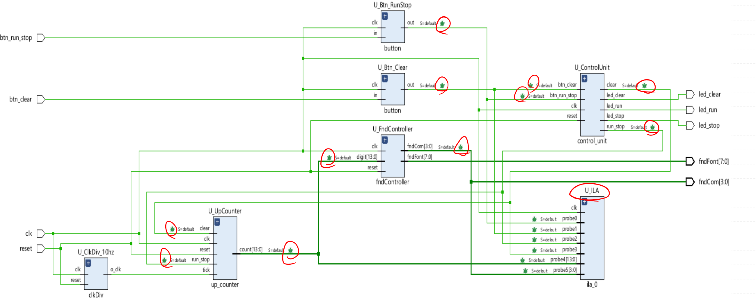
top모듈에서 확인하고 싶은 line에 probe를 연결하여 진행한다.
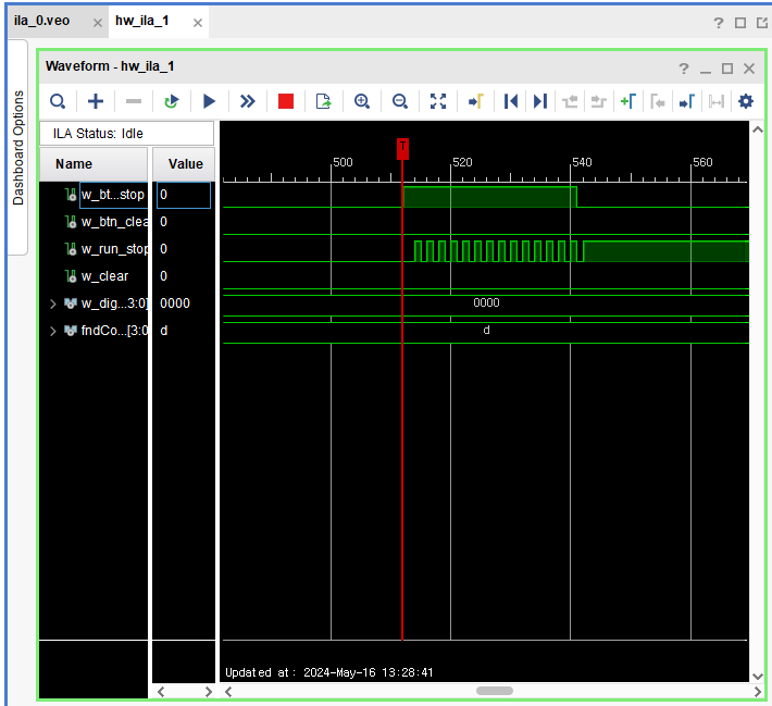
ILA로 확인해본 결과 w_run_stop에서 신호가 비정장적으로 요동치는 것을 확인하였다.
이 과정을 통해 하드웨어의 data흐름을 알 수 있고, 문제가 되는 지점을 파악하기 유리하다.