1D Array
two-element array
한 열에 나열된 안테나 (1D) element 2개가 있다고 해보자
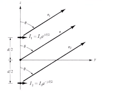
far field에서의 전기장을 계산해보면 다음과 같다.
E2=θ^jη4πrβI0le−jβrcosθAF2
여기에서 AF2는 어레이에 의해 발생되는 array factor이고 다음과 같이 exponential의 조합으로 나타내진다.
AF2=e+j(βdcosθ+δ)/2+e−j(βdcosθ+δ)/2=2cos[21(βdcosθ+δ)]
δ가 안테나 간의 phase 차이, d는 안테나 사이의 물리적 간격, β는 phase constant이다.
주파수를 얼마로 하느냐, 안테나의 간격d을 얼마로 하느냐, 급전을 어떤 phase로 하느냐에 따라서 원하는 방향으로 steering 할 수 있다.
N-element array
이번에는 n개의 element로 확장해보자. 이때에는 array factor가 AFN으로 바뀐다.
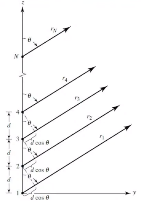
AFN이 N개의 수열로 표현이 되는데 잘 정리하면 sin분의 sin 형식으로 나타나게 되는것을 확인 할 수 있다.
AFN=1+ej(βdcosθ+δ)+ej2(βdcosθ+δ)+⋯+ej(N−1)(βdcosθ+δ)=exp[j(2N−1)ψ]sin(ψ/2)sin(Nψ/2),ψ=βdcosθ+δ
1D Array pattern
GTotal =GElement ×GArray Factor
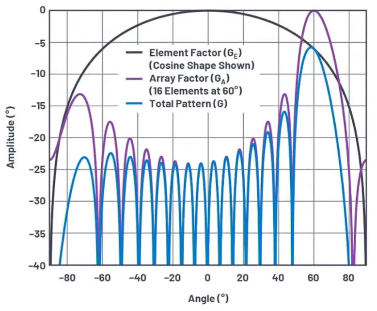
어레이 패턴을 나타내보면 한개의 element에 대한 pattern에 array factor에 의한 term을 곱해준것으로 나타내진다.
2D Array
이번에는 2D array로 확장해보자.
M by N 개의 2D array로 안테나를 배치한다고 하면
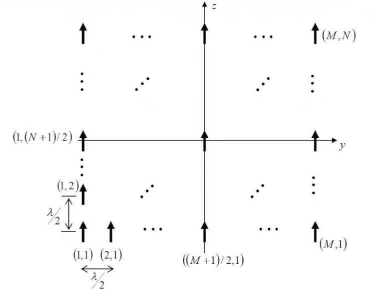
앞의 Array Factor AFN를 AFM×N로 확장하면 된다.
- N element
AFN=exp[j(2N−1)ψ]sin(ψ/2)sin(Nψ/2)ψ=βdcosθ+δ
−>
- MXN elements
AFM×N=exp[j(2M−1)ψy+j(2N−1)ψz]sin(ψy/2)sin(Mψy/2)sin(ψz/2)sin(Nψz/2)ψy=βdsinθsinϕ+δyψz=βdcosθ+δz
2D Array pattern
δ를 얼마로 하느냐에 따라 steering이 다르게 나타나고 θ 방향으로 빔 집속이 가능하다.
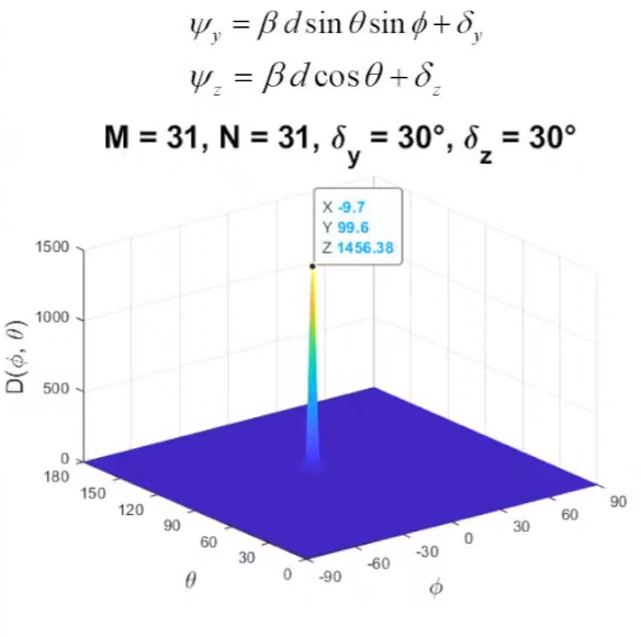
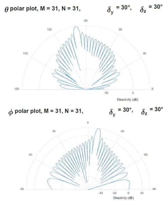
Main lobe가 특정방향으로 있고 그 주변으로 side lobe가 발생한다.
Side Lobe Suppression
레이더에서 사이드 로브를 줄이는 것이 중요한데
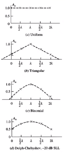
사이드 로브를 줄이는 방법으로 각 element에 급전되는 전류의 크기를 tapering 하는 방법이 있다.
각 element마다 uniform한 파워 급전 하면 사이드 로브 레벨 커진다.
반면에 amplitude tapering을 하니까 side lobe level이 10dB정도 낮아졌다.
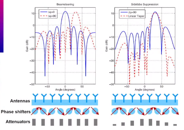
또한 어떤 Polinominal을 가지고 tapering을 하느냐에 따라서도 특성이 달라진다.