💡 Ethernet, USB, and SATA are meant for "outside the box communications" and data exchanges between whole systems. When there is a need to implement a communication between an integrated circuit such as a microcontroller and a set of relatively slow peripherals, there is no point in using any excessively complex protocols.
I2C (Inter-integrated Circuit)
NXP(formerly Philips), 1982
I2C bus's original purpose was to provide and easy way to connect a CPU to peripheral chips in a television set.
Connecting the peripherals to the microcontroller parallel address and data busses resulted in lots of wiring on the PCB.
=> I2C only requires two wires for connecting all the peripherals
I2C is a multi-master protocol that uses two signal lines. The two I2C signals are calles serial data(SDA) and serial clock(SCL). There is no need of chip select or arbitration logic.

The IC that initiates a data transfer on the bus is considered the bus master.
1. The master will issue a START condition. This acts as an "Attention" signal to all of the connected devices.
2. All ICs on the bus will listen to the bus for incoming data.
3. Then the master sends the ADDRESS of the device it wants to access, along with an indication of whether the access is Read or Write operation.
4. Having received the address, all ICs will compare it with their own address.
5. If it does not match, they simply wait until the bus is release by the stop condition
6. If the address matches, however, the chip will produce a response called the ACKNOWLEDGE signal.
7. Once the master receives the ACKNOWLEDGE, it can start transmitting or receiving DATA.
8. When all is done, the master will issue the STOP condition.
At the electrical level, there is actually no conflict if multiple devices try to put any logic level on the I2C bus lines simultaneously. If one of the drivers tries to write a logic ZERO and the other a logic ONE, then the open-drain and pull-up structure ensures that there will be no short-circuit and the bus will actually see a logic ZERO transiting on the bus.
I2C has some advanced features, like extended bus addressing, clock stretching, and the very specific 3.4Mb/s high speed mode.
SPI (Serial peripheral Interface)
Freescale(Formely Motorola), 1979
SPI was defined as the external microcontroller bus and was used to connect the microcontroller peripherals with four wires.
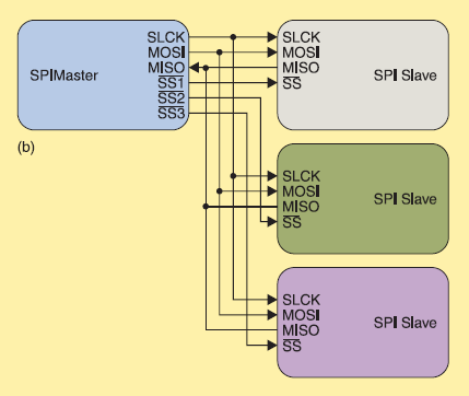
- SCLK(Clock Signal) : sent from the bus master to all slaves ; all the SPI signals are synchronous to the clock signal.
- SSn(Slave Select Signal) : used to select the slave the master communicates with
- MOSI(Master Out-Slave In) : A data line from the master to the slaves
- MISO(Master In-Slave Out) : A data line from the slaves to the master
SPI is a single-master communication protocol.
1. When the SPI master wishes to send data a slave and/or request information from it, it selects a slave by pulling the corresponding SS line low
2. And it activates the clock signal at the clock frequency usable by the master and the slave.
SPI does not define any maximum data rate nor any particular addressing scheme
✔ Both protocols are well suited for comm between integrated circuits for slow comm with on-board peripherals.
✔ I2C needs two lines only, whereas SPI formally defines at least four signals and more if you add slaves.
✔ If data must be transferred at "high speed", SPI is cleary the protocol of choice over I2C. SPI is full duplex; I2C is not.
✔ I2c is much more elegant that SPI and that SPI is a very "rough" protocol.
- I2C is elegant because it offers very advanced features, such as automatic multi-master conflicsts handling and built-in addressing management.
- SPI is very easy to understand and to implement and offers a great deal of flexibility for extensions and variations
=> Using SPI may require more work but offers increased data transfer performance and almost total freedom.
✔ SPI is better suited to applications in which devices transfer data streams, whereas I2C is better at multi-master "register access" applications.
📑
DOI : 10.1109/MIM.2009.4762946
https://ieeexplore.ieee.org/abstract/document/4762946