네트워크 망분리 구현 (VLAN) (교육 20일차)

##########
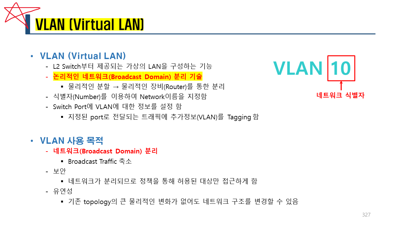
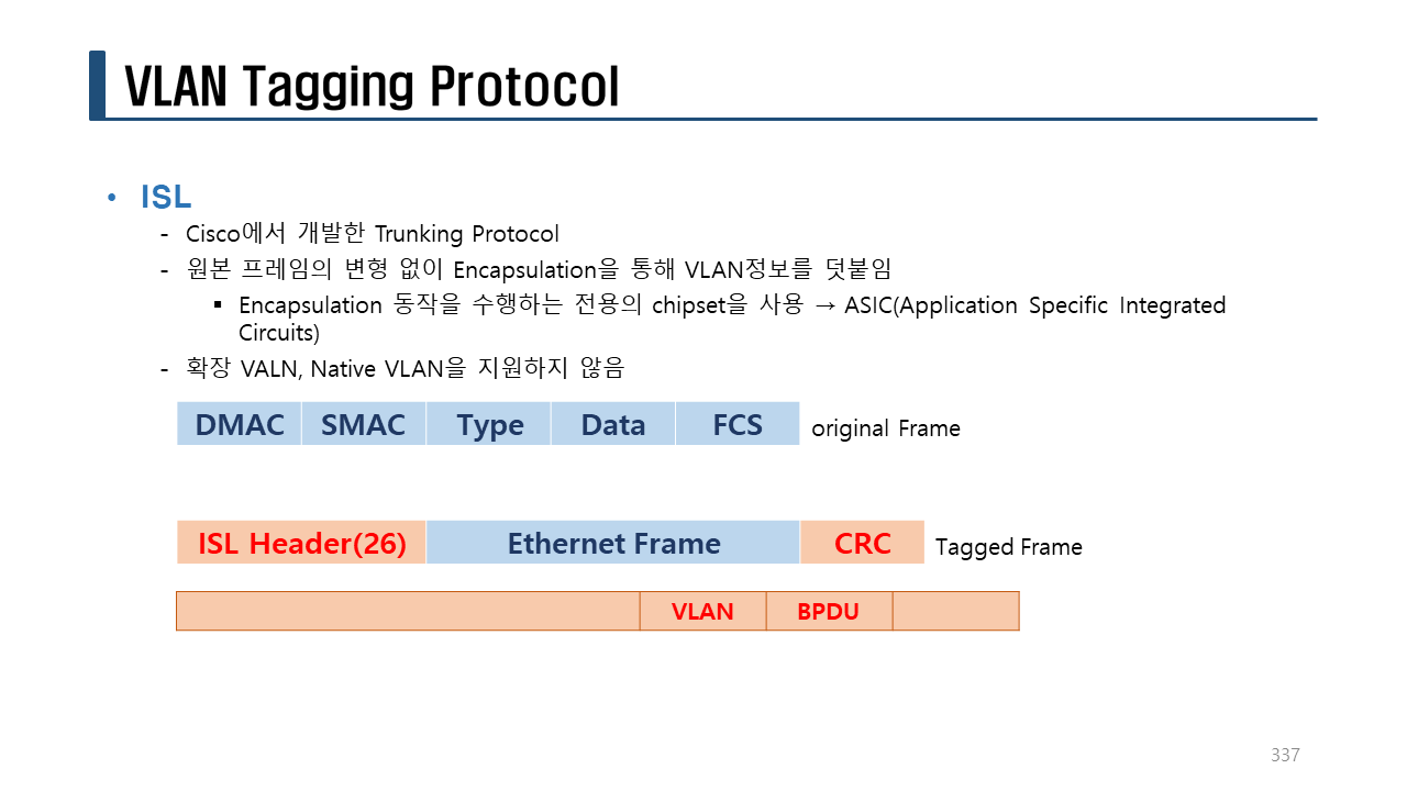
👉 VLAN
##########
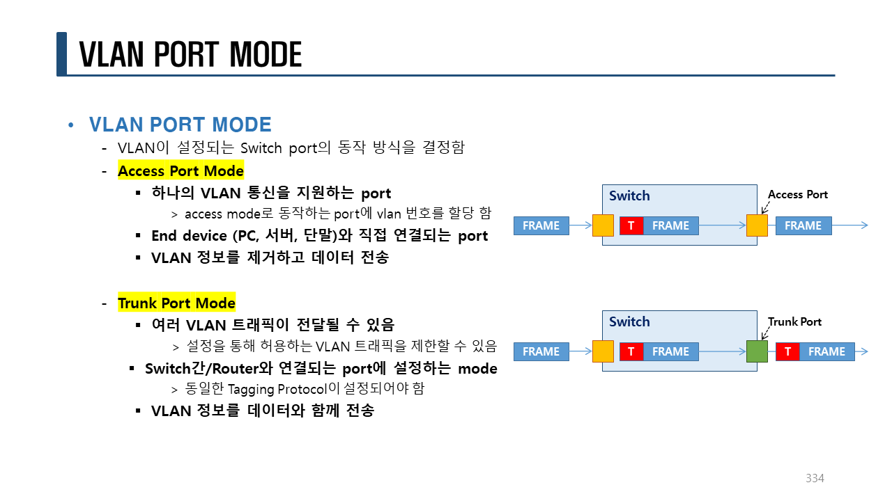
Switchport
Access mode: 하나의 VLAN을 사용하여 통신하는 모드로 주로 PC, 서버, 단말 장비들이 연결되는 포트
Trunk mode : 다수의 VLAN을 사용하여 통신하는 모드로 Switch, IP Phone 과 같은 장비가 연결되는 포트
VLAN 생성 형식:
conf t
vlan <번호>
name <이름> <-- 생략하면 기본값은 자동으로 설정된다.
VLAN 확인 형식:
sh vlan
sh vlan brief
인터페이스를 access mode로 설정할 경우 특정 VLAN에 포함 시키는 형식:
int <인터페이스명>
switchport mode access
switchport access vlan <번호>
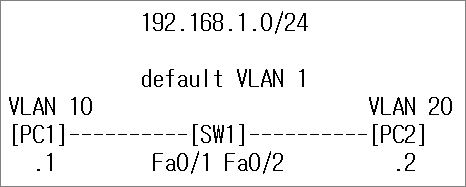
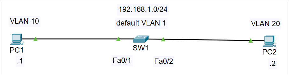
실습> VLAN 설정하기 1
파일명: vlan1.pkt
!
en
conf t
hostname SW1
end
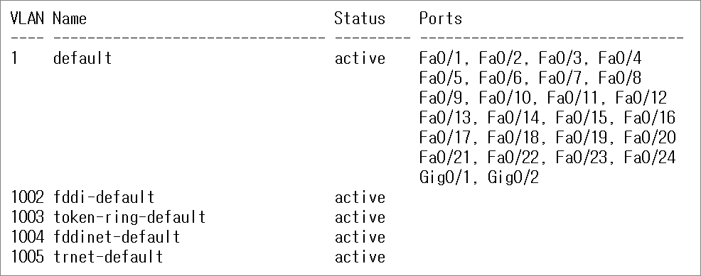
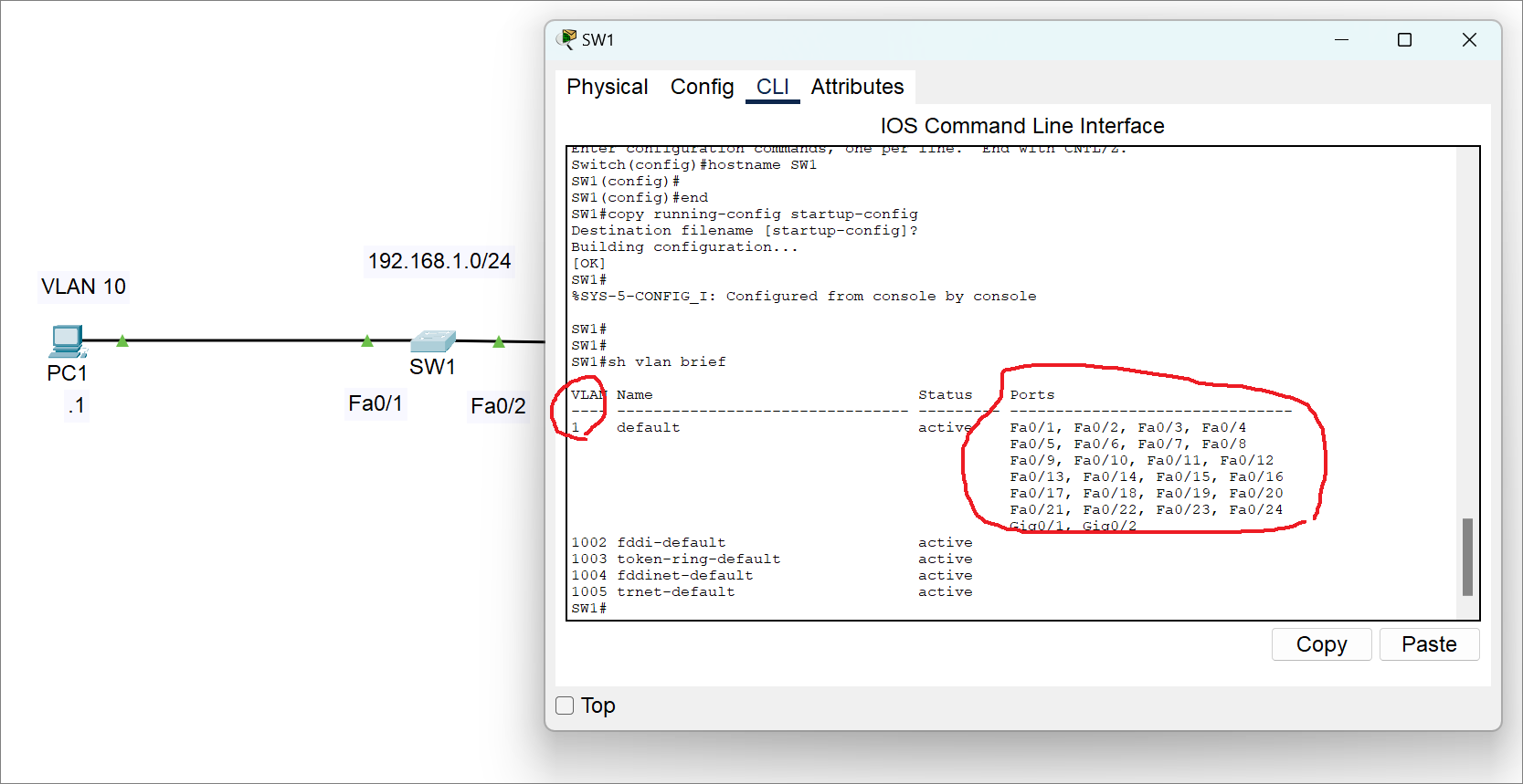
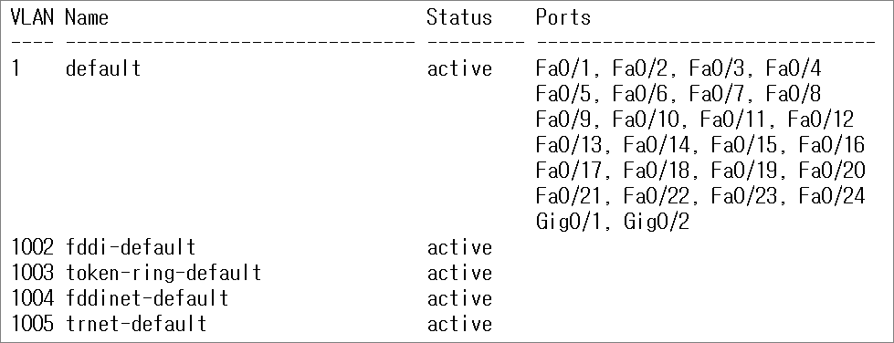
sh vlan b
!
SW1#sh vlan b
!SW1
en
sh vlan b
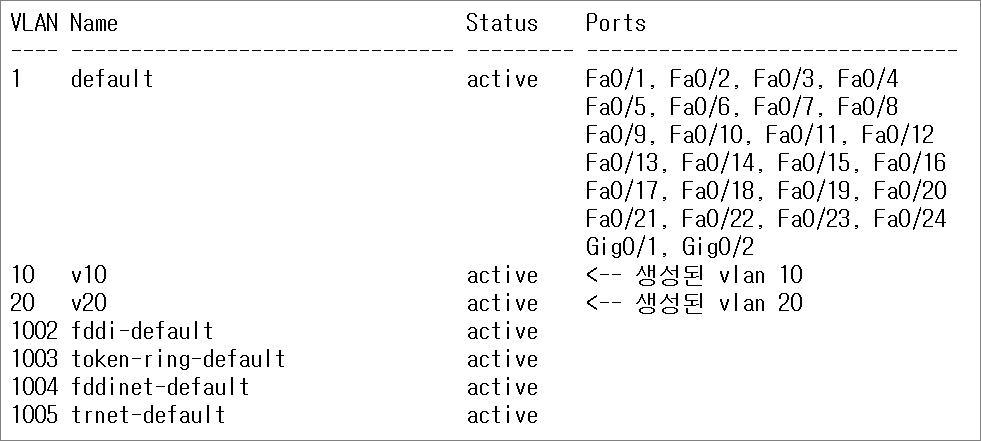
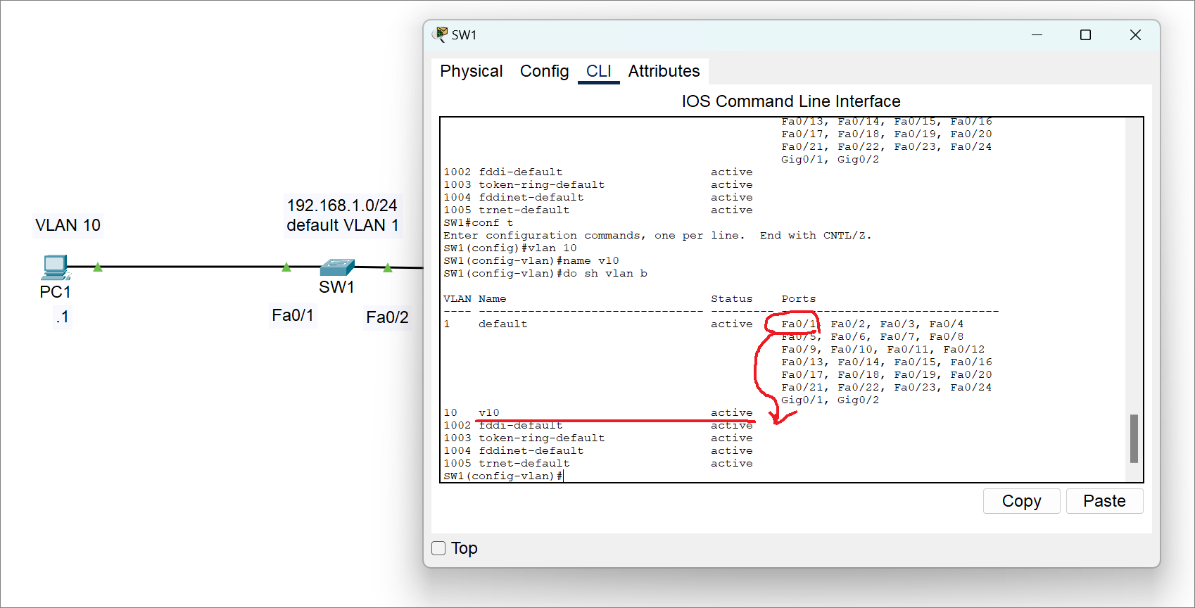
conf t
vlan 10
name v10
vlan 20
name v20
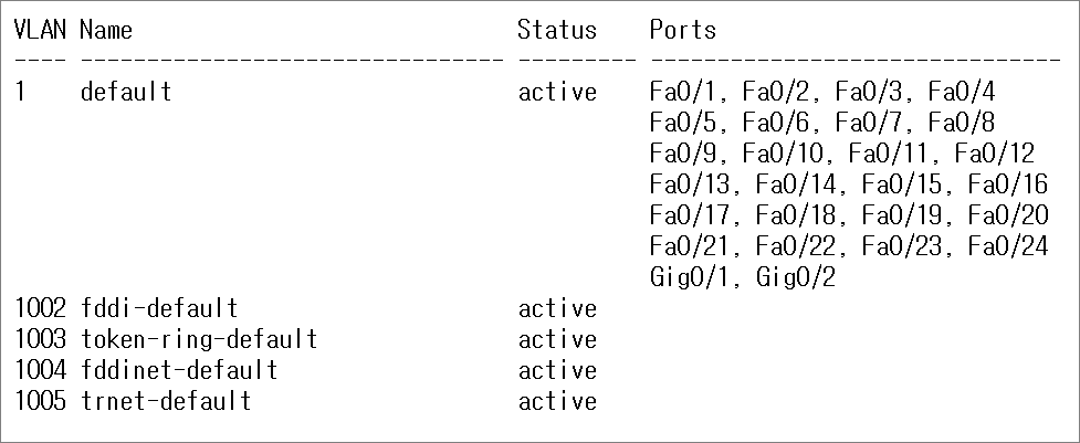
do sh vlan b
!
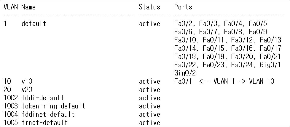
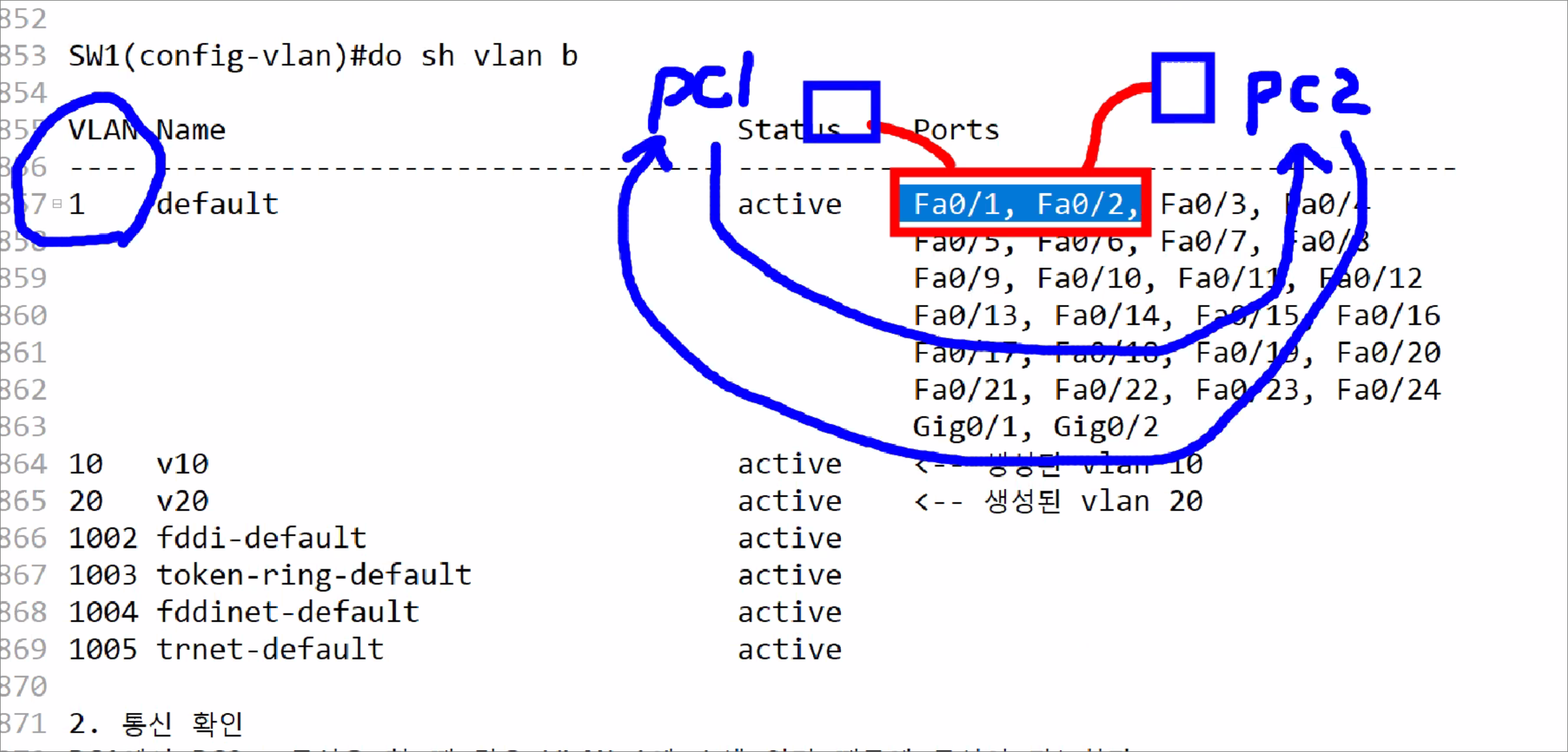
SW1(config-vlan)#do sh vlan b
2. 통신 확인
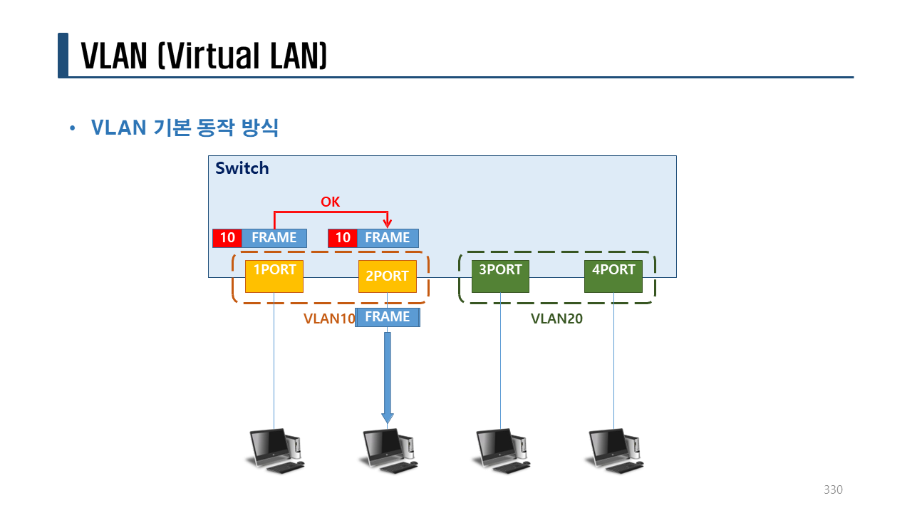
PC1에서 PC2로 통신을 할 때 같은 VLAN 1에 속해 있기 때문에 통신이 가능하다.
C:>ping 192.168.1.2
Pinging 192.168.1.2 with 32 bytes of data:
Reply from 192.168.1.2: bytes=32 time=1ms TTL=128
Reply from 192.168.1.2: bytes=32 time=3ms TTL=128
Reply from 192.168.1.2: bytes=32 time<1ms TTL=128
Reply from 192.168.1.2: bytes=32 time<1ms TTL=128
Ping statistics for 192.168.1.2:
Packets: Sent = 4, Received = 4, Lost = 0 (0% loss),
Approximate round trip times in milli-seconds:
Minimum = 0ms, Maximum = 3ms, Average = 1ms
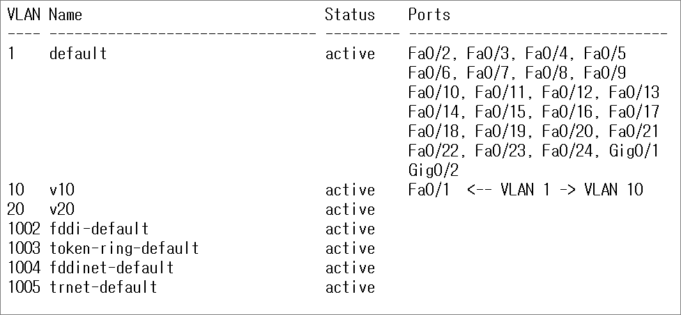
3. VLAN 분리
Fa0/1 : VLAN 1 -> VLAN 10
Fa0/2 : VLAN 1 -> VLAN 20
Fa0/1 포트를 변경한다.
!SW1
conf t
int fa0/1
switchport mode access
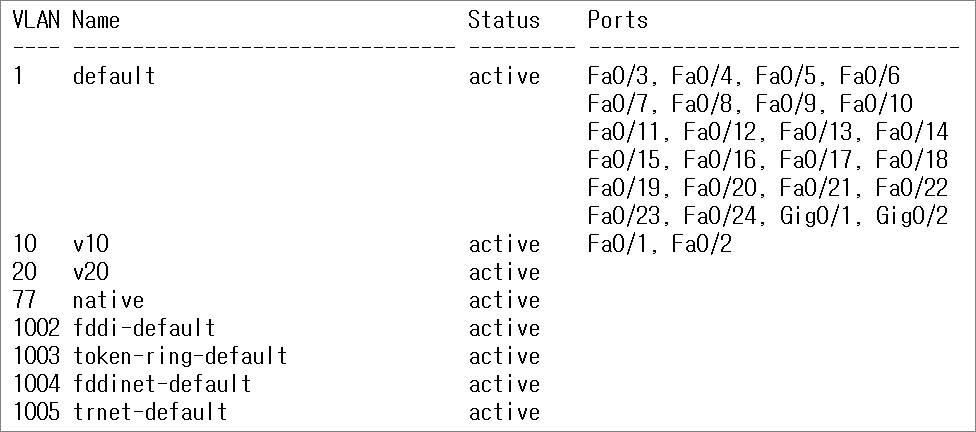
switchport access vlan 10
do sh vlan b
!
Switch(config-if)#do sh vlan b
2. 통신 확인
PC1에서 PC2로 통신을 할 때 같은 VLAN 1에 속해 있기 때문에 통신이 가능하다.
C:>ping 192.168.1.2
Pinging 192.168.1.2 with 32 bytes of data:
Reply from 192.168.1.2: bytes=32 time=1ms TTL=128
Reply from 192.168.1.2: bytes=32 time=3ms TTL=128
Reply from 192.168.1.2: bytes=32 time<1ms TTL=128
Reply from 192.168.1.2: bytes=32 time<1ms TTL=128
Ping statistics for 192.168.1.2:
Packets: Sent = 4, Received = 4, Lost = 0 (0% loss),
Approximate round trip times in milli-seconds:
Minimum = 0ms, Maximum = 3ms, Average = 1ms
3. VLAN 분리
Fa0/1 : VLAN 1 -> VLAN 10
Fa0/2 : VLAN 1 -> VLAN 20
Fa0/1 포트를 변경한다.
!SW1
conf t
int fa0/1
switchport mode access
switchport access vlan 10
do sh vlan b
!
Switch(config-if)#do sh vlan b
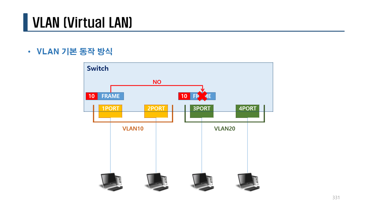
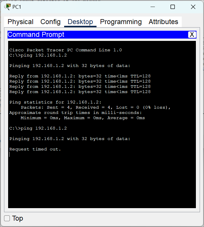
PC1에서 PC2로 ping test를 하면 통신이 안된다.
이유는? PC1과 PC2가 192.168.1.0/24 의 같은 네트워크에 속해 있어도 VLAN 정보가 다르므로 서로 통신할 수 없다.
C:>ping 192.168.1.2
Pinging 192.168.1.2 with 32 bytes of data:
Request timed out.
Request timed out.
Request timed out.
Request timed out.
Ping statistics for 192.168.1.2:
Packets: Sent = 4, Received = 0, Lost = 4 (100% loss),
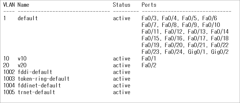
Fa0/2 포트를 변경한다.
!SW2
conf t
int fa0/2
switchport mode access
switchport access vlan 20
do sh vlan b
!
Switch(config-if)#do sh vlan b
원래대로 돌려놓기
!SW1
conf t
int f0/1
switchport mode access
switchport access vlan 1
int f0/2
switchport mode access
switchport access vlan 1
no vlan 10
no vlan 20
end
sh vlan b
!
PC1에서 PC2로 ping test를 하면 통신이 잘~~ 된다.
이유는? PC1과 PC2가 192.168.1.0/24 의 같은 네트워크에 속해 있고 VLAN 정보가 같으므로 서로 통신할 수 있다.
C:>ping 192.168.1.2
Pinging 192.168.1.2 with 32 bytes of data:
Reply from 192.168.1.2: bytes=32 time<1ms TTL=128
Reply from 192.168.1.2: bytes=32 time<1ms TTL=128
Reply from 192.168.1.2: bytes=32 time=1ms TTL=128
Reply from 192.168.1.2: bytes=32 time<1ms TTL=128
Ping statistics for 192.168.1.2:
Packets: Sent = 4, Received = 4, Lost = 0 (0% loss),
Approximate round trip times in milli-seconds:
Minimum = 0ms, Maximum = 1ms, Average = 0ms
실습> VLAN 설정하기 2
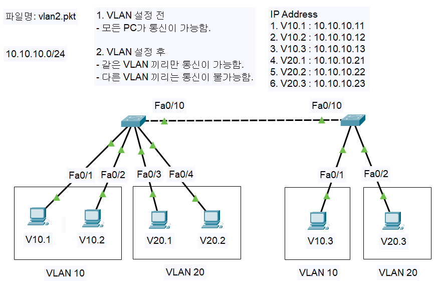
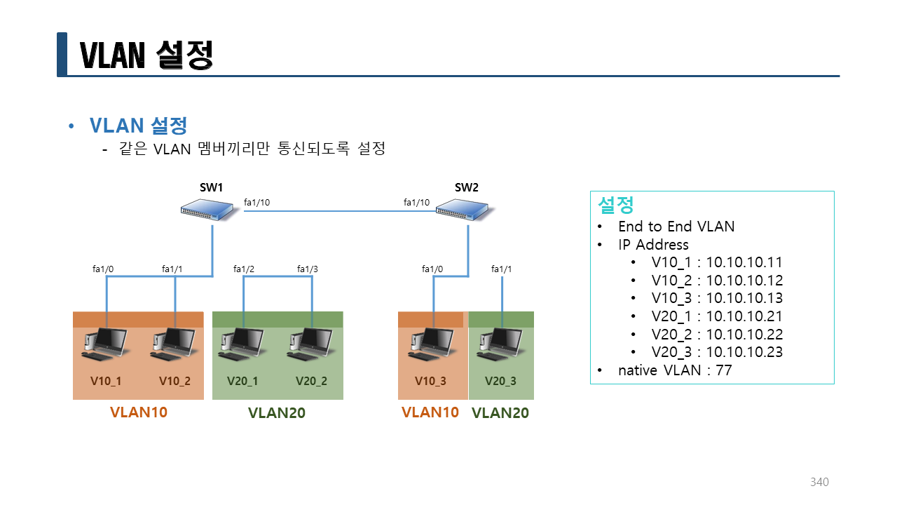
1. VLAN 정보
10.10.10.0/24
– VLAN10: PC1, PC2, PC5
– vlan name: v10
– VLAN20: PC3, PC4, PC6
– vlan name: v20
2. PC 설정
PC1:
IPv4 Address: 10.10.10.11
Subnet Mask: 255.255.255.0
Default Gateway: X
DNS Server: X
PC2:
IPv4 Address: 10.10.10.12
Subnet Mask: 255.255.255.0
Default Gateway: X
DNS Server: X
PC3:
IPv4 Address: 10.10.10.21
Subnet Mask: 255.255.255.0
Default Gateway: X
DNS Server: X
PC4:
IPv4 Address: 10.10.10.22
Subnet Mask: 255.255.255.0
Default Gateway: X
DNS Server: X
PC5:
IPv4 Address: 10.10.10.13
Subnet Mask: 255.255.255.0
Default Gateway: X
DNS Server: X
PC6:
IPv4 Address: 10.10.10.23
Subnet Mask: 255.255.255.0
Default Gateway: X
DNS Server: X
3. 통신 확인
PC1에서 모두 통신을 확인한다.
모두 통신이 되어야 한다.
C:>ping 10.10.10.12
C:>ping 10.10.10.13
C:>ping 10.10.10.21
C:>ping 10.10.10.22
C:>ping 10.10.10.23
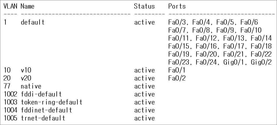
4. VLAN 확인
!SW1
en
sh vlan b
!SW2
en
sh vlan b
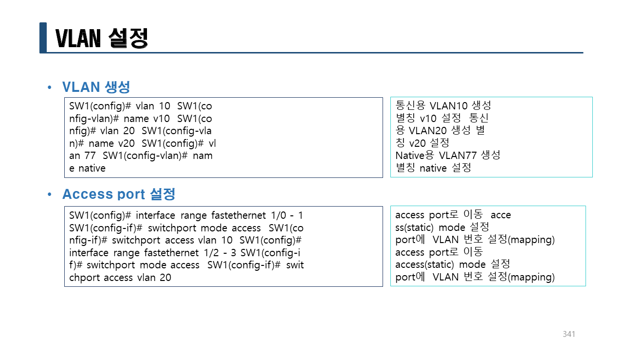
5. VLAN 생성
!SW1
conf t
hostname SW1
no ip domain-lookup
vlan 10
name v10
vlan 20
name v20
vlan 77
name native
!SW2
conf t
hostname SW2
no ip domain-lookup
vlan 10
name v10
vlan 20
name v20
vlan 77
name native
6. VLAN 연결
Fa0/1 : VLAN 1 -> VLAN 10
Fa0/2 : VLAN 1 -> VLAN 10
!SW1
int fa0/1
switchport mode access
switchport access vlan 10
int fa0/2
switchport mode access
switchport access vlan 10
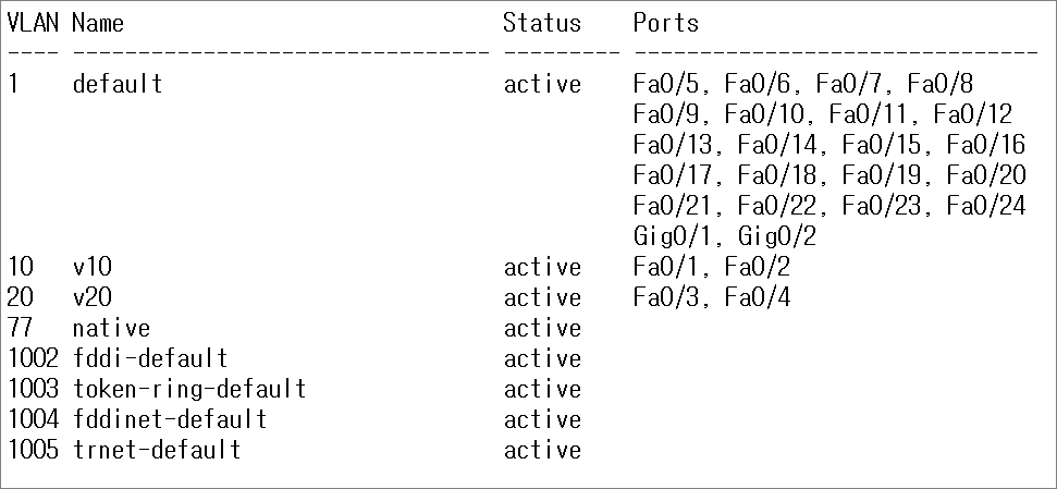
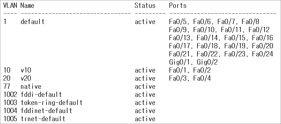
do sh vlan b
!
SW1(config-if)#do sh vlan b
!SW1
int fa0/3
switchport mode access
switchport access vlan 20
int fa0/4
switchport mode access
switchport access vlan 20
do sh vlan b
!
SW1(config-if)# do sh vlan b
!SW2
int fa0/1
switchport mode access
switchport access vlan 10
int fa0/2
switchport mode access
switchport access vlan 20
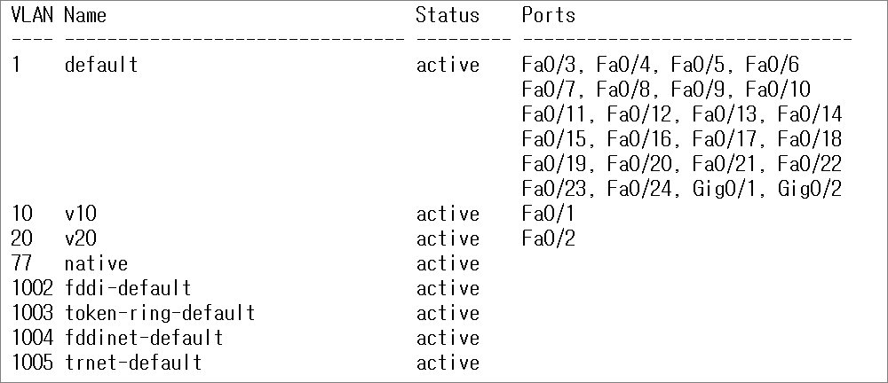
do sh vlan b
!
SW2(config-if)# do sh vlan b
6. 통신 확인
PC1에서 모두 통신을 확인한다.
모두 통신이 되어야 한다.
C:>ping 10.10.10.12 <-- 통신 가능 SW1에 같은 VLAN에 있기 때문이다.
C:>ping 10.10.10.13 <-- 통신 불가능 SW2에 있기 때문이다.
C:>ping 10.10.10.21 <-- 통신 불가능 SW1에 있지만 다른 VLAN에 있기 때문이다.
SW1에 같은 VLAN(VLAN 10)에 소속되어 있기 때문에 통신이 가능하다.
C:>ping 10.10.10.12
Pinging 10.10.10.12 with 32 bytes of data:
Reply from 10.10.10.12: bytes=32 time<1ms TTL=128
Reply from 10.10.10.12: bytes=32 time<1ms TTL=128
Reply from 10.10.10.12: bytes=32 time<1ms TTL=128
Reply from 10.10.10.12: bytes=32 time<1ms TTL=128
Ping statistics for 10.10.10.12:
Packets: Sent = 4, Received = 4, Lost = 0 (0% loss),
Approximate round trip times in milli-seconds:
Minimum = 0ms, Maximum = 0ms, Average = 0ms
SW1에 다른 VLAN(VLAN 20)에 소속되어 있기 때문에 통신이 불가능하다.
C:>ping 10.10.10.21
Pinging 10.10.10.21 with 32 bytes of data:
Request timed out.
Request timed out.
Request timed out.
Request timed out.
Ping statistics for 10.10.10.21:
Packets: Sent = 4, Received = 0, Lost = 4 (100% loss),
VLAN(VLAN 10)에 소속되어 있지만 다른 스위치(SW2)에 있기 때문에 통신이 불가능하다.
이것을 통신을 하게 설정하기 위해서는 trunk를 설정해야 한다.
C:>ping 10.10.10.13
Pinging 10.10.10.13 with 32 bytes of data:
Request timed out.
Request timed out.
Request timed out.
Request timed out.
Ping statistics for 10.10.10.13:
Packets: Sent = 4, Received = 0, Lost = 4 (100% loss),
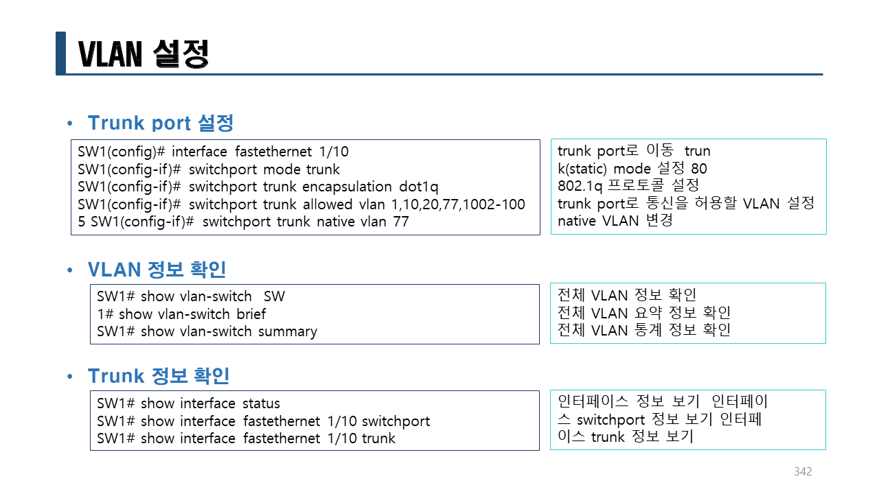
7. trunk 포트 설정
!SW1
int fa0/10
switchport mode trunk
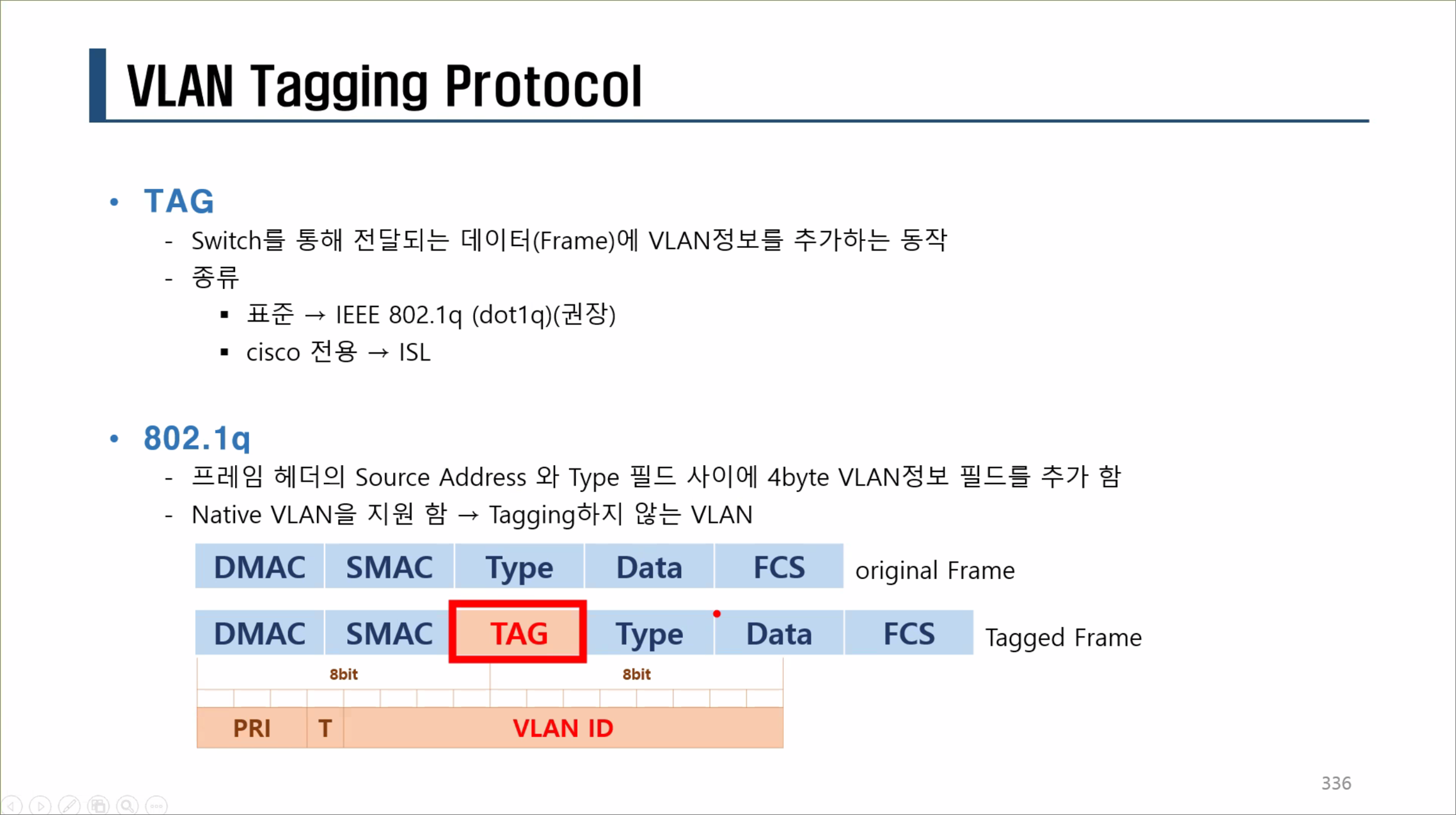
switchport trunk encapsulation dot1q <-- 패킷트레이서에서 지원이 안되므로 여기서는 설정할 수 없다. (실장비에서는 설정이 가능하다.)
switchport trunk allowed vlan 1,10,20,77,1002-1005
!
여기까지 설정해도 통신이 가능하다. 하지만 SW2에도 동일하게 설정해보자.
!SW2
int fa0/10
switchport mode trunk
switchport trunk encapsulation dot1q <-- 패킷트레이서에서 지원이 안되므로 여기서는 설정할 수 없다. (실장비에서는 설정이 가능하다.)
switchport trunk allowed vlan 1,10,20,77,1002-1005
!
trunk 포트를 설정하고 SW1에 연결된 PC1에서 SW2에 연결된 PC5로 ping test를 하면 통신이 잘 되는 것을 확인할 수 있다.
C:>ping 10.10.10.13
Pinging 10.10.10.13 with 32 bytes of data:
Reply from 10.10.10.13: bytes=32 time<1ms TTL=128
Reply from 10.10.10.13: bytes=32 time<1ms TTL=128
Reply from 10.10.10.13: bytes=32 time<1ms TTL=128
Reply from 10.10.10.13: bytes=32 time<1ms TTL=128
Ping statistics for 10.10.10.13:
Packets: Sent = 4, Received = 4, Lost = 0 (0% loss),
Approximate round trip times in milli-seconds:
Minimum = 0ms, Maximum = 0ms, Average = 0ms
trunk 포트를 설정하고 SW1에 연결된 PC3에서 SW2에 연결된 PC으로 ping test를 하면 통신이 잘 되는 것을 확인할 수 있다.
C:>ping 10.10.10.23
Pinging 10.10.10.23 with 32 bytes of data:
Reply from 10.10.10.23: bytes=32 time=1ms TTL=128
Reply from 10.10.10.23: bytes=32 time<1ms TTL=128
Reply from 10.10.10.23: bytes=32 time<1ms TTL=128
Reply from 10.10.10.23: bytes=32 time=90ms TTL=128
Ping statistics for 10.10.10.23:
Packets: Sent = 4, Received = 4, Lost = 0 (0% loss),
Approximate round trip times in milli-seconds:
Minimum = 0ms, Maximum = 90ms, Average = 22ms
7. trunk 포트 설정 디버깅
Simulation mode에서 확인한다.
!SW1
int fa0/10
switchport mode trunk
switchport trunk encapsulation dot1q <-- 패킷트레이서에서 지원이 안되므로 여기서는 설정할 수 없다. (실장비에서는 설정이 가능하다.)
switchport trunk allowed vlan 1,10,77,1002-1005 <-- VLAN 20을 삭제한다.
!
!SW2
int fa0/10
switchport mode trunk
switchport trunk encapsulation dot1q <-- 패킷트레이서에서 지원이 안되므로 여기서는 설정할 수 없다. (실장비에서는 설정이 가능하다.)
switchport trunk allowed vlan 1,10,77,1002-1005 <-- VLAN 20을 삭제한다.
!
PC1에서 PC5로 통신을 확인한다.
C:>ping 10.10.10.13 <-- 통신 가능
PC3에서 PC6으로 통신을 확인한다.
C:>ping 10.10.10.23 <-- 통신 불가능
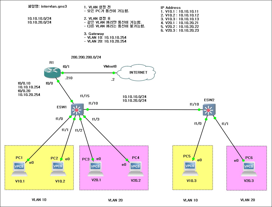
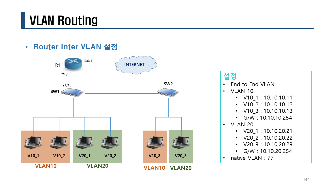
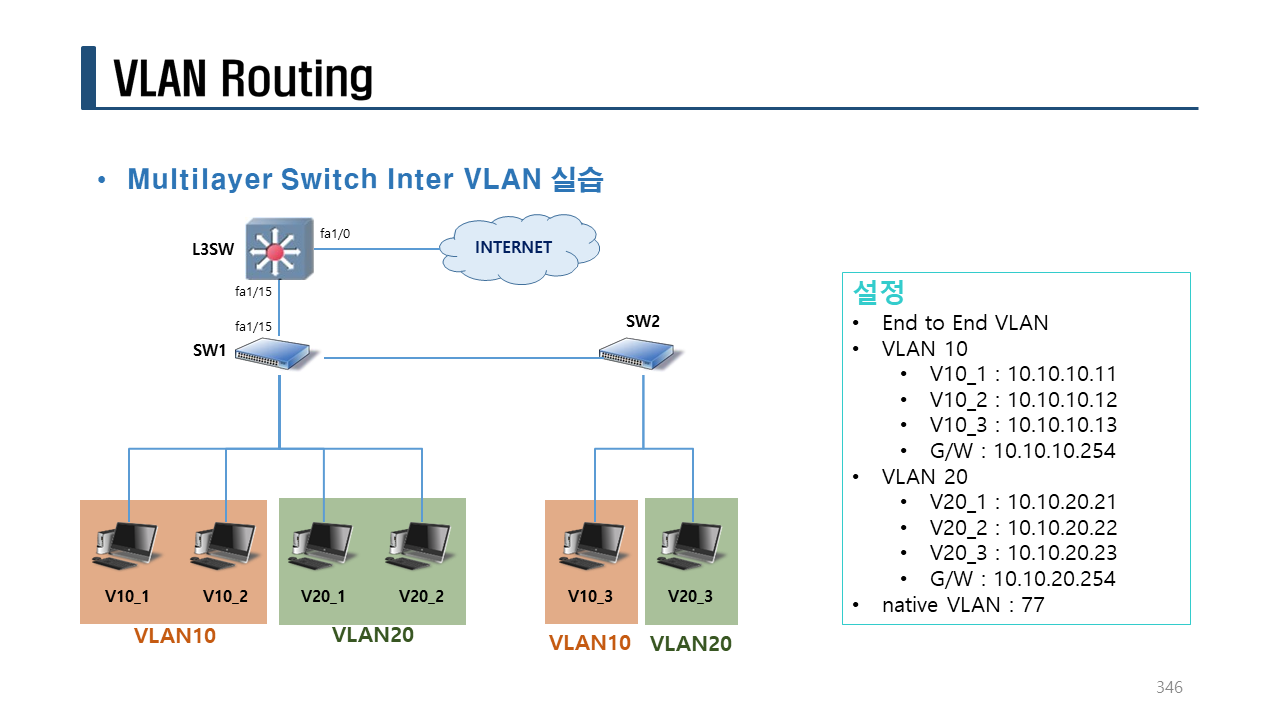
실습> Inter VLAN 설정하기
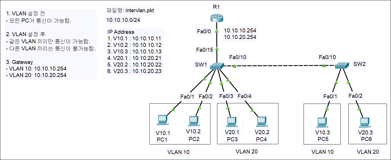
1. VLAN 정보
10.10.10.0/24
– VLAN10: PC1, PC2, PC5
– vlan name: v10
– VLAN20: PC3, PC4, PC6
– vlan name: v20
2. PC 설정
PC1:
IPv4 Address: 10.10.10.11
Subnet Mask: 255.255.255.0
Default Gateway: 10.10.10.254
DNS Server: X
PC2:
IPv4 Address: 10.10.10.12
Subnet Mask: 255.255.255.0
Default Gateway: 10.10.10.254
DNS Server: X
PC3:
IPv4 Address: 10.10.20.21
Subnet Mask: 255.255.255.0
Default Gateway: 10.10.20.254
DNS Server: X
PC4:
IPv4 Address: 10.10.10.22
Subnet Mask: 255.255.255.0
Default Gateway: 10.10.20.254
DNS Server: X
PC5:
IPv4 Address: 10.10.10.13
Subnet Mask: 255.255.255.0
Default Gateway: 10.10.10.254
DNS Server: X
PC6:
IPv4 Address: 10.10.20.23
Subnet Mask: 255.255.255.0
Default Gateway: 10.10.20.254
DNS Server: X
3. 통신 확인
PC1에서 모두 통신을 확인한다.
모두 통신이 되어야 한다.
C:>ping 10.10.10.12
C:>ping 10.10.10.13
C:>ping 10.10.10.21
C:>ping 10.10.10.22
C:>ping 10.10.10.23
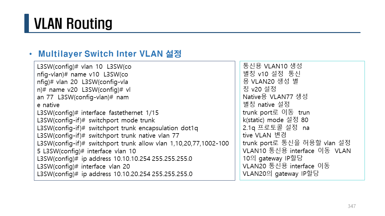
4. VLAN 생성
Fa0/1 : VLAN 1 -> VLAN 10
Fa0/2 : VLAN 1 -> VLAN 10
Fa0/3 : VLAN 1 -> VLAN 20
Fa0/4 : VLAN 1 -> VLAN 20
!SW1
conf t
hostname SW1
no ip domain-lookup
line con 0
logging synchronous
exec-timeout 0 0
vlan 10
name v10
vlan 20
name v20
vlan 77
name native
exit
int range fa0/1 - 2
switchport mode access
switchport access vlan 10
int range fa0/3-4
switchport mode access
switchport access vlan 20
int fa0/10
switchport mode trunk
! switchport trunk encapsulation dot1q <-- 패킷트레이서에서 지원이 안되므로 여기서는 설정할 수 없다. (실장비에서는 설정이 가능하다.)
switchport trunk allowed vlan 1,10,20,77,1002-1005
switchport trunk native vlan 77
!
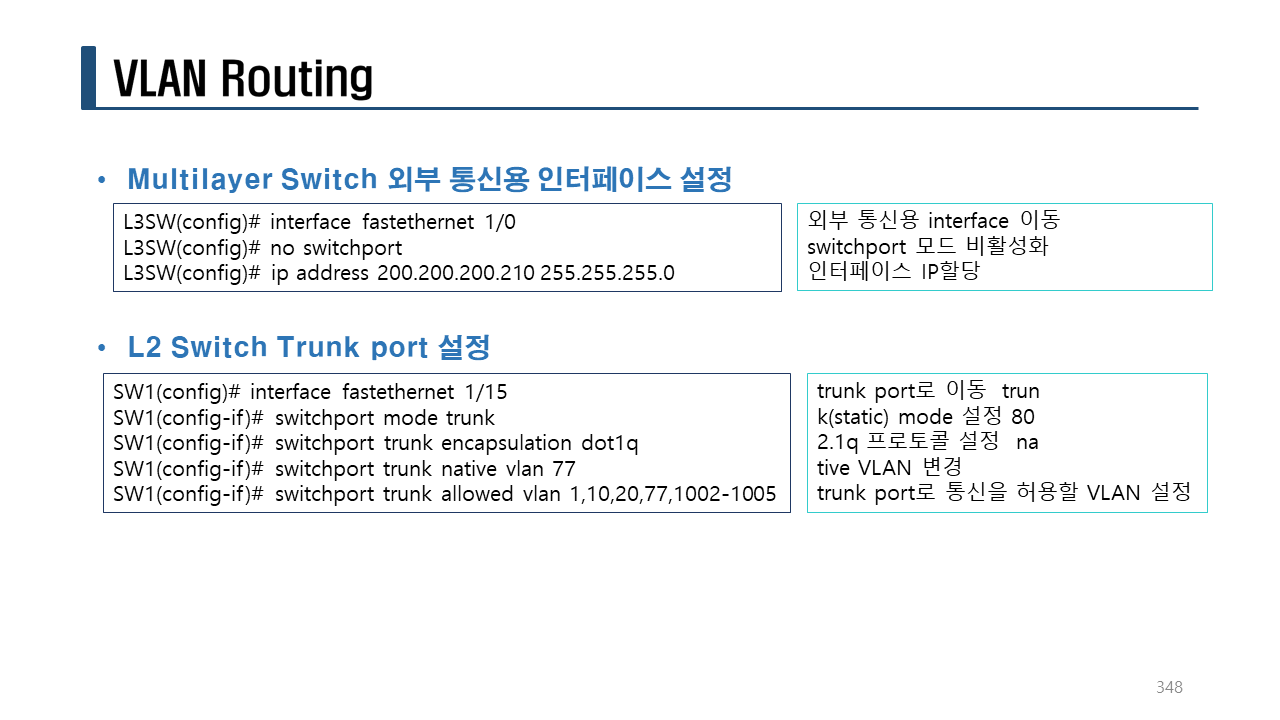
int fa0/15
switchport mode trunk
! switchport trunk encapsulation dot1q <-- 패킷트레이서에서 지원이 안되므로 여기서는 설정할 수 없다. (실장비에서는 설정이 가능하다.)
switchport trunk native vlan 77
switchport trunk allowed vlan 1,10,20,77,1002-1005
do sh vlan b
!
Fa0/1 : VLAN 1 -> VLAN 10
Fa0/2 : VLAN 1 -> VLAN 20
!SW2
conf t
hostname SW2
no ip domain-lookup
line con 0
logging synchronous
exec-timeout 0 0
vlan 10
name v10
vlan 20
name v20
vlan 77
name native
int fa0/1
switchport mode access
switchport access vlan 10
int fa0/2
switchport mode access
switchport access vlan 20
int fa0/10
switchport mode trunk
! switchport trunk encapsulation dot1q <-- 패킷트레이서에서 지원이 안되므로 여기서는 설정할 수 없다. (실장비에서는 설정이 가능하다.)
switchport trunk allowed vlan 1,10,20,77,1002-1005
do sh vlan b
!
SW1(config-if)# do sh vlan b
SW2(config-if)# do sh vlan b
5. 통신 확인
trunk 포트를 설정하고 SW1에 연결된 PC1에서 SW2에 연결된 PC5로 ping test를 하면 통신이 잘 되는 것을 확인할 수 있다.
C:>ping 10.10.10.13
Pinging 10.10.10.13 with 32 bytes of data:
Reply from 10.10.10.13: bytes=32 time<1ms TTL=128
Reply from 10.10.10.13: bytes=32 time<1ms TTL=128
Reply from 10.10.10.13: bytes=32 time<1ms TTL=128
Reply from 10.10.10.13: bytes=32 time<1ms TTL=128
Ping statistics for 10.10.10.13:
Packets: Sent = 4, Received = 4, Lost = 0 (0% loss),
Approximate round trip times in milli-seconds:
Minimum = 0ms, Maximum = 0ms, Average = 0ms
trunk 포트를 설정하고 SW1에 연결된 PC3에서 SW2에 연결된 PC으로 ping test를 하면 통신이 잘 되는 것을 확인할 수 있다.
C:>ping 10.10.10.23
Pinging 10.10.10.23 with 32 bytes of data:
Reply from 10.10.10.23: bytes=32 time=1ms TTL=128
Reply from 10.10.10.23: bytes=32 time<1ms TTL=128
Reply from 10.10.10.23: bytes=32 time<1ms TTL=128
Reply from 10.10.10.23: bytes=32 time=90ms TTL=128
Ping statistics for 10.10.10.23:
Packets: Sent = 4, Received = 4, Lost = 0 (0% loss),
Approximate round trip times in milli-seconds:
Minimum = 0ms, Maximum = 90ms, Average = 22ms
6. R1 설정
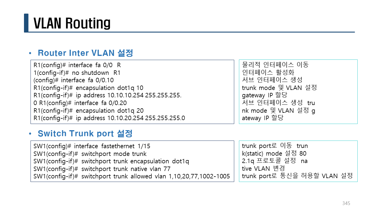
R1 라우터에서 Inter VLAN을 설정한다.
!R!
en
conf t
hostname R1
no ip domain-lookup
line con 0
exec-timeout 0 0
logging synchronous
!
int fa0/0
no sh
int fa0/0.10 <-- VLAN10에 GW를 설정하기 위한 서브 인터페이스를 생성한다.
encapsulation dot1Q 10 <-- VLAN 10에 대한 dot1q를 설정한다. (vlan 번호가 같아야 한다.)
ip add 10.10.10.254 255.255.255.0
int fa0/0.20 <-- VLAN20에 GW를 설정하기 위한 서브 인터페이스를 생성한다.
encapsulation dot1Q 20 <-- VLAN 20에 대한 dot1q를 설정한다. (vlan 번호가 같아야 한다.)
ip add 10.10.20.254 255.255.255.0
end
sh ip int b
!
R1#sh ip int b
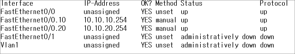
7. 통신 확인
PC1 -> PC3 (다른 VLAN 20에 속한 네트워크이지만 Inter VLAN 설정에 의해서 통신이 가능하다.)
C:>ping 10.10.20.21
Pinging 10.10.20.21 with 32 bytes of data:
Request timed out.
Reply from 10.10.20.21: bytes=32 time<1ms TTL=127
Reply from 10.10.20.21: bytes=32 time<1ms TTL=127
Reply from 10.10.20.21: bytes=32 time<1ms TTL=127
Ping statistics for 10.10.20.21:
Packets: Sent = 4, Received = 3, Lost = 1 (25% loss),
Approximate round trip times in milli-seconds:
Minimum = 0ms, Maximum = 0ms, Average = 0ms
PC1 -> PC4 (다른 VLAN 20에 속한 네트워크이지만 Inter VLAN 설정에 의해서 통신이 가능하다.)
C:>ping 10.10.20.22
Pinging 10.10.20.22 with 32 bytes of data:
Request timed out.
Reply from 10.10.20.22: bytes=32 time<1ms TTL=127
Reply from 10.10.20.22: bytes=32 time<1ms TTL=127
Reply from 10.10.20.22: bytes=32 time<1ms TTL=127
Ping statistics for 10.10.20.22:
Packets: Sent = 4, Received = 3, Lost = 1 (25% loss),
Approximate round trip times in milli-seconds:
Minimum = 0ms, Maximum = 0ms, Average = 0ms
PC1 -> PC6 (다른 SW2, VLAN 20에 속한 네트워크이지만 trunk 설정과 Inter VLAN 설정에 의해서 통신이 가능하다.)
C:>ping 10.10.20.23
Pinging 10.10.20.23 with 32 bytes of data:
Request timed out.
Reply from 10.10.20.23: bytes=32 time<1ms TTL=127
Reply from 10.10.20.23: bytes=32 time<1ms TTL=127
Reply from 10.10.20.23: bytes=32 time<1ms TTL=127
Ping statistics for 10.10.20.23:
Packets: Sent = 4, Received = 3, Lost = 1 (25% loss),
Approximate round trip times in milli-seconds:
Minimum = 0ms, Maximum = 0ms, Average = 0ms
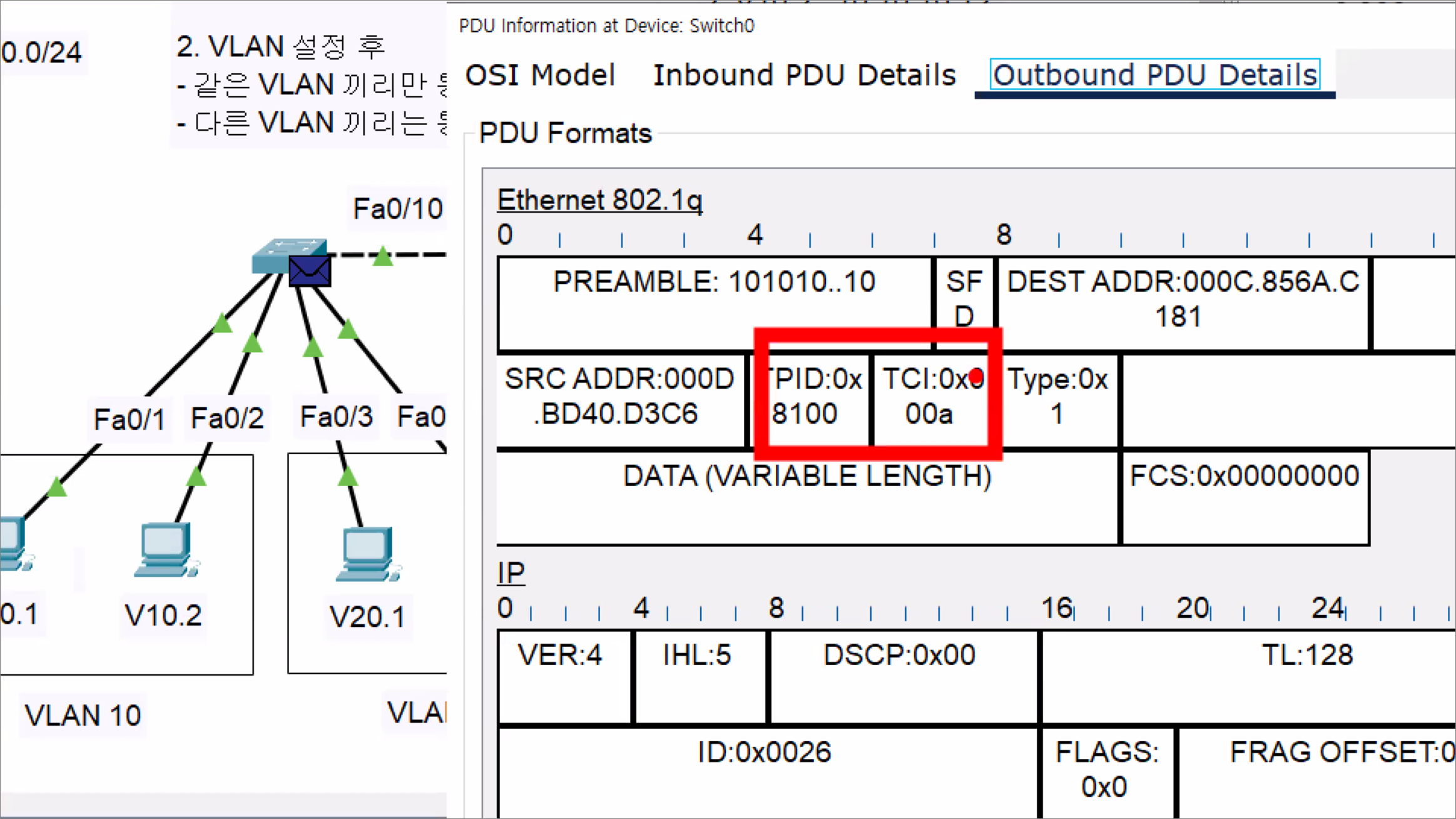
8. 분석
Simulation mode에서 분석한다.
PC1 -> PC6 (다른 SW2, VLAN 20에 속한 네트워크이지만 trunk 설정과 Inter VLAN 설정에 의해서 통신이 가능하다.)
echo Request
– PC1 -> (Fa0/1)SW1(Fa0/15) -> (Fa0/0)R1(Fa0/0) -> (Fa0/15)SW1(Fa0/10) -> (Fa0/10)SW2(Fa0/2) -> PC6
echo Reply
– PC6 -> (Fa0/2)SW2(Fa0/10) -> (Fa0/10)SW1(Fa0/15) -> (Fa0/0)R1(Fa0/0) -> (Fa0/15)SW1(Fa0/1) -> PC1
C:>ping 10.10.20.23
Pinging 10.10.20.23 with 32 bytes of data:
Reply from 10.10.20.23: bytes=32 time=10ms TTL=127
Reply from 10.10.20.23: bytes=32 time<1ms TTL=127
Reply from 10.10.20.23: bytes=32 time<1ms TTL=127
Reply from 10.10.20.23: bytes=32 time<1ms TTL=127
Ping statistics for 10.10.20.23:
Packets: Sent = 4, Received = 4, Lost = 0 (0% loss),
Approximate round trip times in milli-seconds:
Minimum = 0ms, Maximum = 10ms, Average = 2ms
실습> GNS3에서 Inter VLAN 설정하기