NAT - 라우터에서 해주는 설정
(라우터에서 다른 라우터로 나갈 때 사용하는 보호조치)
- inside, outside
STATIC NAT -> 1:1 IP교환
- ip nat inside source static 내부ip 공인ip
POOL NAT -> N:1 IP교환 (pool interface)
1) access-list 리스트 생성
- access-list 리스트이름 permit 네트워크 wildcark mask
2) pool 범위 설정
- ip nat pool pool이름 공인ip주소시작범위 공인ip주소마지막범위 prefix-length 프리픽스값
3-1) pool nat 설정
- ip nat inside source list 리스트이름 pool pool이름
3-2-1) pool interface 설정 (overload 설정)
- ip nat inside source list 리스트이름 pool pool이름 int 케이블이름
3-2-2) pool 설정
- ip nat inside source list 리스트이름 pool pool이름
1. GNS3
1-1. 아이콘 이미지 변경법
우클릭 > Change symbol
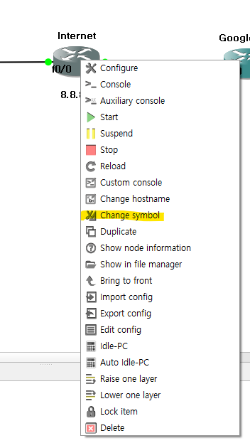
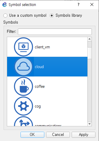
카테고리별로 이미지를 선택할 수 있음
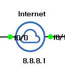
변경 후 필드에 아이콘 이미지가 변경된 것을 확인
2. SecuerCRT
MobaXterm과 같은
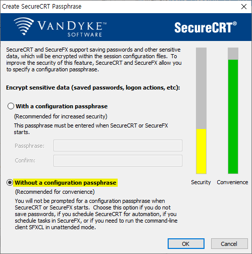
2-1. 설치
링크 : https://www.vandyke.com/products/securecrt/
2-2. 설치 경로
C드라이브 > Program Files > VanDyke Software > Clients

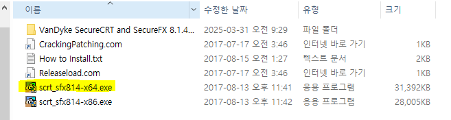
2-3. crak 적용
x64 > SecureCRT
3개의 파일 모두 설치된 파일로 붙여넣기
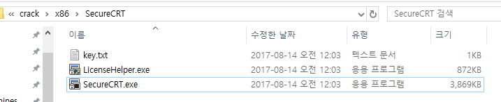
시작(윈도우키) > SecureCRT 8.1 실행 후 라이센스 입력 부분에 crak에 포함된 key.txt 파일의 내용을 전체 복사 ➡ 붙여넣기
2-4. 스키마, 글꼴 설정 수정
C:\Users\4gl\AppData\Roaming\VanDyke\Config
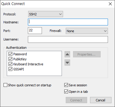
2-6. 사용법
세션 등록하는 창
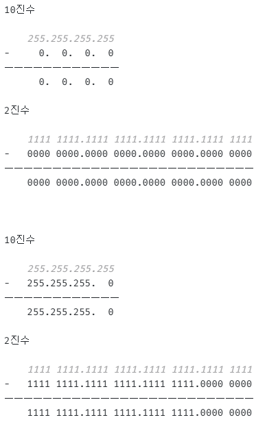
3. wildcard mask
ip route 0.0.0.0 0.0.0.0 nexthop_ip
이때 앞에 0.0.0.0은 네트워크 주소고 뒤에 0.0.0.0은 network/subnet mask임
- 0.0.0.0(network/subnet mask) = 255.255.255.255(wildcard mask)
NOT 연산을 통해 값을 구할 수 있음
4. GNS3 활용 실습 문제
4-0. access-list?
- access-list를 사용하는 이유
공인IP로 연결을 하도록 설정을 했는데 현재 내부, 외부 모두 ping으로 접근이 가능함
때문에 내부는 접근하지 못하도록 차단할 때 사용하는게 access-list임
4-1. ip, static route 설정 실습 문제
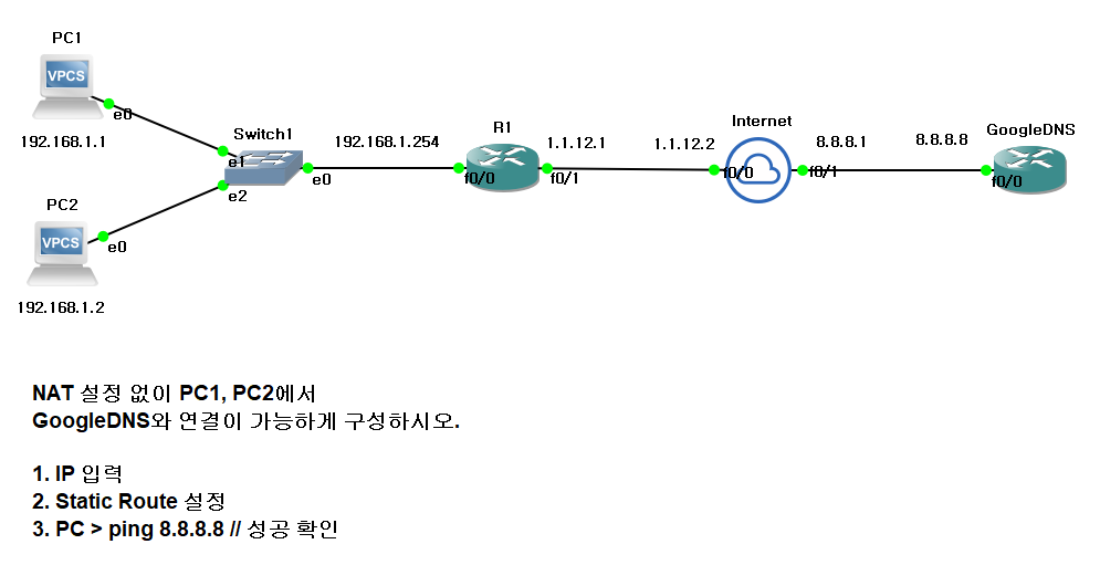
- Internet으로 설정한 장비는 라우터 장비이다.
4-1-1. 실습
- R1에서는 모든 ip로 나갈 수 있게 설정
- GoogleDNS에서는 PC 네트워크만 연결되도록 설정
PC1
ip 192.168.1.1/24 192.168.1.254
save
PC2
ip 192.168.1.2/24 192.168.1.254
save
R1
conf t
int f0/0
ip add 192.168.1.254 255.255.255.0
no sh
int f0/1
ip add 1.1.12.1 255.255.255.0
no sh
end
conf t
ip route 0.0.0.0 0.0.0.0 1.1.12.2
end
wr
Internet
conf t
int f0/0
ip add 1.1.12.2 255.255.255.0
no sh
int f0/1
ip add 8.8.8.1 255.255.255.0
no sh
end
wr
GoogleDNS
conf t
int f0/0
ip add 8.8.8.8 255.255.255.0
no sh
end
conf t
ip route 192.168.1.0 255.255.255.0 8.8.8.1
end
wr
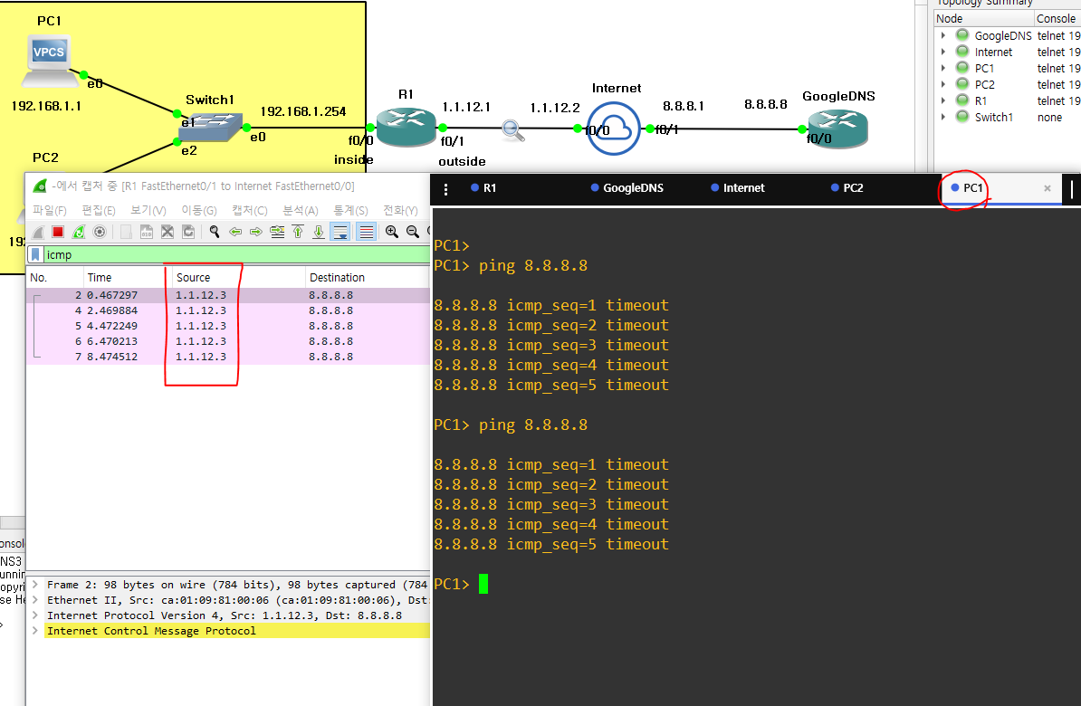
4-1-2. Static NAT 설정 문제
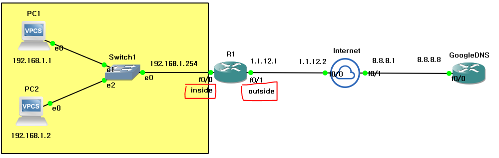
- Static NAT
1 : 1 ➡ 192.168.1.1 : 1.1.12.3 (PC1)
1 : 1 ➡ 192.168.1.2 : 1.1.12.4 (PC2)
R1
conf t
int f0/0
ip nat inside
conf t
int f0/1
ip nat outside
end
conf t
ip nat inside source static 192.168.1.1 1.1.12.3
R1
conf t
ip nat inside source static 192.168.1.2 1.1.12.4
R1에서 sh ip nat tr을 통해 NAT 설정 확인 가능
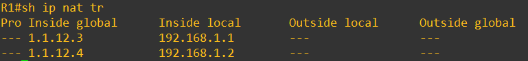
PC1에서 8.8.8.8로 ping을 전송하면 1.1.12.3 이라는 ip로 변환되어 나가는것을 확인할 수 있음
4-1-3. Pool 설정 (overload)
- ip nat inside source list 1 pool NAT (overload)
overload는 default 값으로 입력하지 않으면 overload가 적용됨
R1에서 PC2 NAT 설정 삭제
R1
conf t
no ip nat inside source static 192.168.1.2 1.1.12.4
access-list를 사용해 pool(outside ip) 생성
-
R1
conf t
access-list 1 permit 192.168.1.0 0.0.0.255 -
R1
conf t
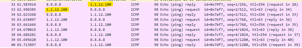
ip nat pool NAT 1.1.12.100 1.1.12.200 prefix-length 24
(pool의 이름은 NAT이며 ip는 1.1.12.100 ~ 1.1.12.200까지 제공하며 프리픽스 /24 값을 제공)
ip nat inside source list 1 pool NAT
(4-1-2 실습하며 NAT 설정을 pool 로 변경)
PC2에서 ping을 쓰면 나가는 ip가 1.1.12.100인 것을 확인할 수 있음
ip nat inside source list 1 pool NAT interface f0/1
나가는 ip는 한개만 설정할 거고 outside int는 f0/1이다.
4-1-4. pool interface 설정
4-1-3에서 설정한 pool 설정 제거
R1
conf t
no ip nat inside list 1 pool NAT
R1에서 NAT를 interface로 설정
R1
conf t
ip nat inside source list 1 pool NAT interface f0/1
(나가는 ip는 한개만 설정할 거고 outside int는 f0/1이다.)
4-2. NAT 설정
(모든 라우터에 ip, static만 설정되어 있고 NAT 설정이 전혀 없는 상태라고 가정하고 진행)
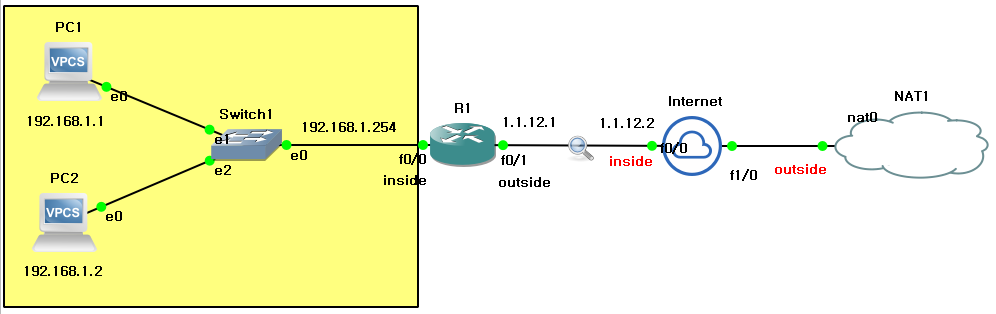
4-2-1. Internet에 NAT 설정
+)R1, Internet에서 NAT Table 확인
Internet
conf t
int f1/0
ip add DHCP
end
conf t
int f0/0
ip nat inside
int f1/0
ip nat outside
end
conf t
ip nat inside source list 1 int f1/0
access-list 1 permit any
end
sh ip nat tr
4-2-2. R1에서 기존 NAT 설정 삭제
+)1번 상황과 비교하여 NAT Table 확인
R1
conf t
int f0/0
no ip nat inside
int f0/1
no ip nat outside
R1에서 NAT가 끊겨서 PC에서 ping 8.8.8.8을 하면 안되는데 내부 정보를 몰라서 안된다고함
때문에 Internet에서 PC 네트워크를 static 설정을 해줘야함
Internet
conf t
ip route 192.168.1.0 255.255.255.0 1.1.12.1
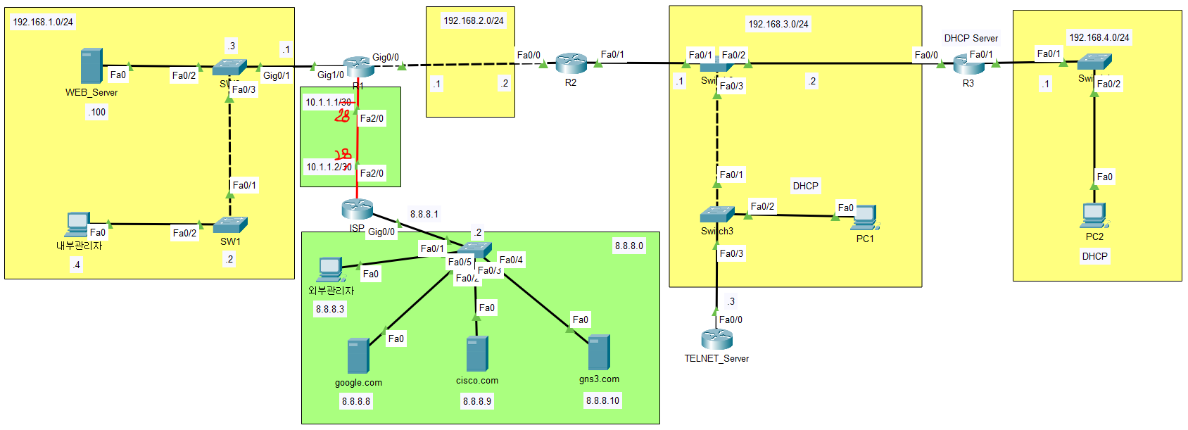
5. Packet Tracer 실습 문제
5-1. NAT Static 설정 실습
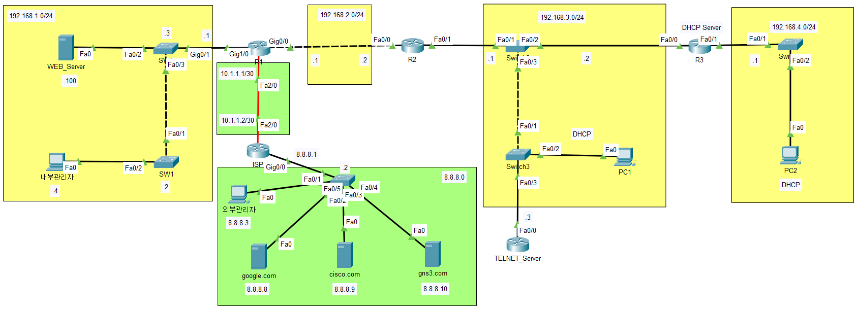
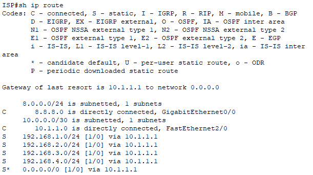
5-1-1. 기존 NAT Overload 설정 삭제, ISP와의 서브넷을 /28로 수정
ISP
conf t
int f2/0
ip add 10.1.1.2 255.255.255.240
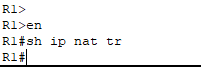
R1
en
sh ip nat tr
(내용 없으므로 설정 삭제할 것이 없음)
int f2/0
ip add 10.1.1.1 255.255.255.240
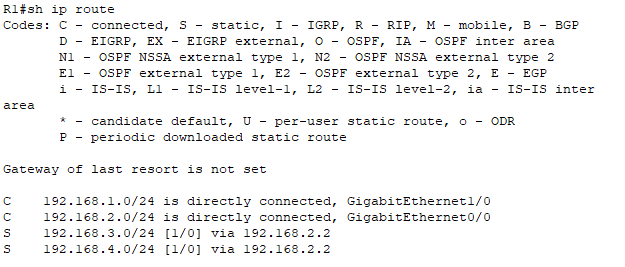
- S* 0.0.0.0 0.0.0.0 설정 추가해줘야함
5-1-2. WEB_Server를 공인 IP 10.1.1.3로 변환
R1
conf t
int g1/0
ip nat inside
int f2/0
ip nat outside
end
conf t
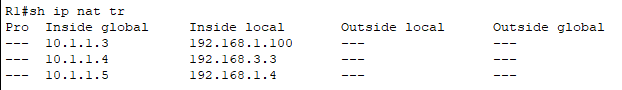
ip nat inside source static 192.168.1.100 10.1.1.3
5-1-3. TELNET_Server를 공인 IP 10.1.1.4로 변환
TELNET_SERVER
conf t
int f0/0
ip add 192.168.3.3 255.255.255.0
no sh
R1
conf t
ip nat inside source static 192.168.3.3 10.1.1.4
5-1-4. 내부관리자는 공인 IP 10.1.1.5로 변환
R1
conf t
ip nat inside source static 192.168.1.4 10.1.1.5
5-1-5. 외부관리자는 내부 접근(icmp, telnet, http)을 확인
R1
en
sh ip nat tr
TELNET_Server
conf t
username ccnp privilege 15 password cisco
line vty 0 4
login local
transport
end
conf t
ip rute 0.0.0.0 0.0.0.0 192.168.3.1
내부관리자
ping 10.1.1.3
ping 10.1.1.4
ping 10.1.1.5telnet 10.1.1.5
- userid : ccnp
- passwd : cisco
web : 10.1.1.3
5-2. R1에서 동적 pool NAT 설정 실습
5-2-1. pool 이름 : NAT
R1
conf t
access-list 1 permit 192.168.0.0 0.0.255.255
5-2-2. pool 범위 : 직접 지정 (현재 /28 감안)
/28 ➡ 252
28-24=4 -> 2^4 = 16 (배수)
사용가능한 범위 : 0~15, 16~31, 32~...
R1
conf t
ip nat pool NAT 10.1.1.6 10.1.1.14 prefix-length 30
prefix-length를 사용해도 되고 netmask를 사용해도 됨
ex) ip nat pool NAT 10.1.1.6 10.1.1.14 netmask 255.255.255.240
5-2-3. 내부 호스트들이 외부와 통신을 할 때 NAT pool을 사용하도록 하시오.
R1
conf t
ip nat inside source list 1 pool NAT
5-3. R1에서 NAT overload 방식을 적용
5-3-1. 기존 pool NAT 삭제
R1
conf t
no ip nat inside source list 1 pool NAT
no ip nat pool NAT 10.1.1.6 10.1.1.14 prefix-length 30
5-3-2. overload 적용
R1
conf t
ip nat inside source access-list 1 int f2/0
end
sh ip nat tr