`timescale 1ns/1psmodule gate(input a,b,output c);
assign c=a&b;
endmodule
위와 같은 부분에서 endmodule 윗부분까지는 모두 코드이다. gate는 이 모듈의 이름이다. 가급적 이것을 파일 이름하고 동일하게 짓자
a,b,c 는 포트 이름을 우리가 임의로 지어준다.
그리고 이 포트를 우리가 구분해 주어야 한다.
input은 입력, output은 출력을 의미한다.
verilog 설계 방식은 4가지 방식이 존재한다.
- data flow 방식
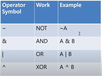
기능들은 위와 같이 구성된다.
NOT gate
module gate(input a, output out);
wire a
wire out;
assign out=~a
endmodule
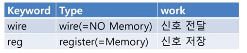
wire = no memory 신호 전달(전선) 그래서 입력이 끝나는 순간 출력도 사라지게 된다.
reg = memory 신호 저장(메모리)
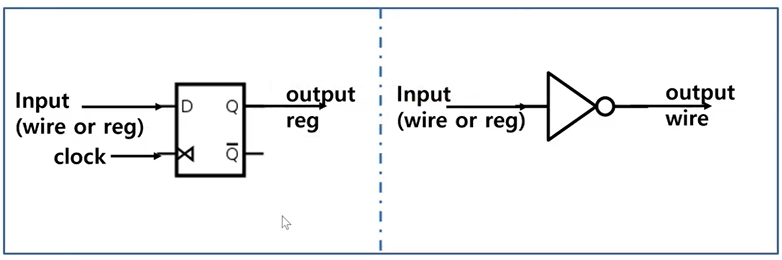
FF 출력은 항상 register 출력이다. 그래서 reg를 사용한다.
이외 반대로 NOT Gate는 그냥 input을 output으로 출력해주면 되기 때문에 wire을 사용해도 된다.
조합회로 = 입력이 바로 출력을 결정(메모리 비존재)
순차회로 = 입력과 상태가 출력을 결정(메모리 존재) - 바로바로 적용되는 동기/변화에 적용되는 비동기 방식
wire D
wire clock;
output reg Q;
output reg nQ;
always@(posedge clock) begin
Q<=D;
nQ<=~D;
end
(posedge clock) : Sensitivity list
always@는 clock이 변화할때 실행된다.(0->1, 1->0) 이때 posedge는 positive edge의 의미로 clock이 0에서 1로 바뀔때 작동하게 된다.
반대로 negedge는 clock이 1에서 0으로 바뀔때 작동한다.
verilog에서는 non-blocking이라고 해서 순서에 상관없이 동시에 실행 되는 것이 존재한다.
Q<=D;
nQ<=~D;
왜 동시에 실행되어야 하는가? verilog는 하드웨어 언어이기 때문에 순차적으로 실행되기 보다는 현재상태를 기준으로 다음 상태를 추론해내는 기능이 필요하다.
if(J==1'b0 && K==1'b0) begin
end
else if(J==1'b0 && K==1'b2) begin
end
else begin
end
if문은 위와 같이 작성할 수 있다.
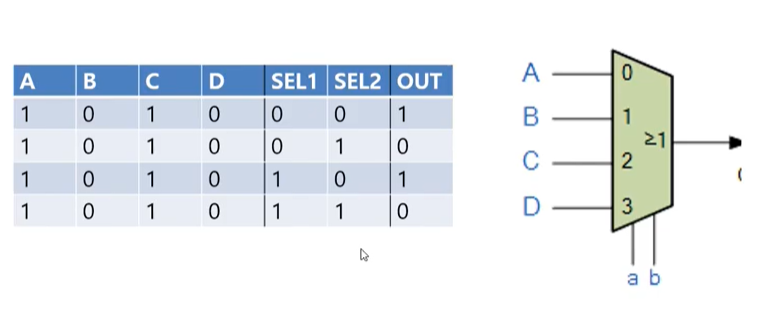
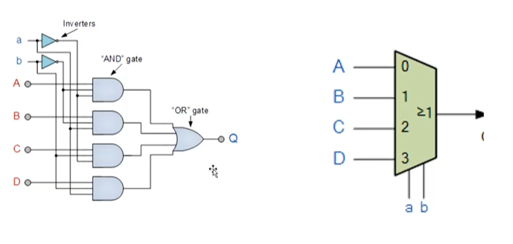
Data Transfer Logic
Digital Multiplexer : 여러개의 입력을 받아 하나의 입력을 선택해주는 역활
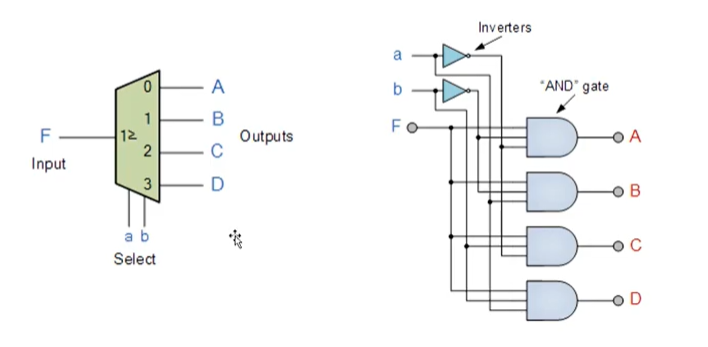
Digital DeMultiplexer
parameter 문과 case 문
`timescale 1ns / 1ps

module det_10111(input clk, reset,x,output reg out );
parameter IDLE =0,S1=1,S10=2,S101=3,S1011=4;
reg[2:0] cur,next;

always @(posedge clk or posedge reset) begin
    if(reset) cur<=IDLE;
    else cur<=next;
end

always @(cur or x) begin
    case(cur)
        IDLE:begin
            out=0;
            next=x? S1:IDLE;
        end

        S1:begin
            out=0;
            next=x? S1:S10;
        end

        S10:begin
            out = 0;
            next = x? S101:IDLE;
        end

        S101:begin
            out=0;
            next=x?S1011:S10;
        end

        S1011:begin
            out=x?1:0;
            next=x?S1:S10;
        end
    endcase
end

endmodule