코드는 아래 링크에서 다운받을 수 있습니다.
https://github.com/Foxhead-Studio/NeRF-Code-Analysis/tree/main
[1] 카메라 이론
이번 장에서는 카메라를 월드의 원하는 지점으로 옮기는 행렬인 Cam to World Matrix(이하 c2w)에 대해 공부하겠습니다. 카메라가 어떤 특정 위치와 방향을 가질 때, 카메라 좌표계에서 본 3D 점을 세계 좌표계로 변환하려면 회전(Rotation) 과 병진(Translation) 을 적용해야 합니다.
NeRF에서는 특정 위치에서 본 물체의 모습을 렌더링 하기 위해 render_poses 라는 변수를 만들고, 여기에 원하는 c2w를 저장합니다. 아래에서 c2w를 만드는데 필요한 요소를 살펴보겠습니다.
1. 병진 행렬: trans_t(t)
trans_t = lambda t : torch.Tensor([
    [1,0,0,0],
    [0,1,0,0],
    [0,0,1,t],
[0,0,0,1]]).float()- 이 함수는 카메라를 Z축 방향으로만큼 평행이동시키는 4×4 병진(translation) 행렬을 생성합니다.
- 동차좌표(homogeneous coordinates)에서에 이 행렬을 곱해보면, 결과는가 되어 Z축으로만큼 이동함을 확인할 수 있습니다.
수식으로는 다음과 같이 나타낼 수 있습니다.
2. X축 회전 행렬: rot_phi(phi)
rot_phi = lambda phi : torch.Tensor([
    [1,0,          0,           0],
    [0,np.cos(phi),-np.sin(phi),0],
    [0,np.sin(phi), np.cos(phi),0],
[0,0, 0, 1]]).float()- 이 함수는 X축(오른손 법칙, right-hand rule 기준) 으로라디안을 회전시키는 4×4 회전 행렬을 생성합니다.
- 오른손 법칙에 따라, X축을 엄지로 두고 네 손가락이 돌아가는 방향을 양(+)의 회전 방향으로 정의합니다.
- 즉, X축이 고정이고,평면 상에서만큼 회전한다고 볼 수 있습니다.
수식으로는, 3차원 회전(동차좌표 포함 시 4×4)에서 잘 알려진 다음 형태가 됩니다.
3. Y축 회전 행렬: rot_theta(th)
rot_theta = lambda th : torch.Tensor([
    [np.cos(th),0,-np.sin(th),0],
    [0,1,0,0],
    [np.sin(th),0, np.cos(th),0],
[0,0,0,1]]).float()- 이 함수는 Y축으로라디안을 회전시키는 4×4 회전 행렬을 생성합니다.
- 보통 우리가 아는 오른손 법칙에 따르면, Y축을 잡고 엄지를 위로 세웠을 때 네 손가락이 돌아가는 방향이 양(+) 회전입니다.
- 그러나 NeRF 코드에서앞에 ‘’가 붙어 있지 않고, 대신와의 위치가 다른 것을 볼 수 있습니다.
- NeRF에서는 카메라 이동의 마지막 단계에서, Y축과 Z축을 뒤바꾸어 카메라가 Z축을 중심으로 회전하도록 반듭니다. 이 때 X 값에도 반전을 주는데, 이것은 전체 행렬을 회전과 평행이동으로 분해할 수 있는 행렬을 만들기 위함입니다. (이에 대한 자세한 설명은 하단 코드에서 다룹니다.)
즉, 이론적으로는 다음과 같은 표준 Y축 회전 행렬을 많이 사용합니다.
하지만 코드에서는
형태로 회전 방향을 반전시킵니다.
4. pose_spherical(theta, phi, radius)
def pose_spherical(theta, phi, radius):
    c2w = trans_t(radius)
    c2w = rot_phi(phi/180.*np.pi) @ c2w
    c2w = rot_theta(theta/180.*np.pi) @ c2w
    c2w = torch.Tensor(np.array([[-1,0,0,0],
                                 [0,0,1,0],
                                 [0,1,0,0],
                                 [0,0,0,1]])) @ c2w
    return c2w
이 함수는 다음 단계를 통해 카메라 좌표계에서 월드 좌표계로 가는 4×4 변환 행렬(Extrinsic Matrix)을 생성합니다.
-
text{trans_t}(radius)
원점에서 Z축 방향(또는 어떤 기준축)으로만큼 떨어진 위치에 카메라를 배치합니다.
즉, 카메라를 구(球) 표면(반지름 = radius) 위에 두기 위한 준비입니다. -
rot_phi(phi/180.*np.pi) @ c2w
X축을 기준으로도 회전(단위는 degree에서 radian으로 변환).
이는 카메라의 고도(Elevation, 보통)를 조절합니다. (예: 위아래로 보는 각도) -
rot_theta(theta/180.*np.pi) @ c2w
Y축을 기준으로도 회전.
이는 카메라의 방위(Azimuth, 보통)를 조절합니다. (예: 좌우로 회전) -
마지막 매트릭스 곱
torch.Tensor(np.array([ [-1, 0, 0, 0], [ 0, 0, 1, 0], [ 0, 1, 0, 0], [ 0, 0, 0, 1] ])) @ c2w- 이 행렬은 위에서 언급한 축 재배열(swizzling)과 부호 반전을 포함합니다.
-과로 Y, Z축을 서로 교환하여 theta 값이 증가할 때 카메라가 Y 축이 아닌 Z축을 중심으로 회전하게 만듭니다. - 그러나 이렇게 만들어진 행렬은 카메라의 이동을 나타내는 행렬로 사용할 수 없습니다. 왜냐하면 이 행렬은 회전과 평행이동으로 분해할 수 없기 때문입니다. 이와 같은 대칭 행렬 은 특정 평면으로 반사 를 포함하고 있기 때문에, 잘못하면 카메라의 축을 반전시켜버릴 수도 있습니다. 따라서 입체 공간상의 물체 이동을 구현하는 다양한 라이브러리는 반사 행렬을 사용하지 않습니다.
- 하지만 X축을 반전시켜 아래와 같은 행렬을 만들면, 이것은 평행이동과 회전변환으로 분해할 수 있습니다. 이러한 행렬의 판별은 아래의 [3].2 에서 좀 더 자세히 다룹니다.
- 이 행렬은 위에서 언급한 축 재배열(swizzling)과 부호 반전을 포함합니다.
요약하면,행렬은 “카메라가각도로 구면 좌표계에서 원점을 바라보되, 거리는만큼 떨어진 지점에 위치” 하도록 만들어주는 변환 행렬입니다.
그리고 마지막 축 재배열을 통해, 결과적으로 카메라가 원점을 바라보게 설정됩니다.
5. 카메라 외부행렬
카메라 외부 행렬(Extrinsic Matrix)은 세계 좌표계 에서 카메라 좌표계 로 변환하는 행렬 (World to Cam) 이며, 회전 행렬과 이동 벡터를 포함합니다.
이 행렬을 동차 좌표계 형태(4×4 행렬)로 나타내면 다음과 같습니다:
여기서,
-: 회전 행렬 (세계 좌표 → 카메라 좌표 변환)
-: 이동 벡터 (세계 좌표계에서의 카메라 위치)
즉,를 사용하면 세계 좌표계의 한 점를 카메라 좌표계의 점로 변환할 수 있습니다:
(동차 좌표계를 사용하여형태로 표현)
6. 카메라 외부 행렬의 역행렬
카메라 외부 행렬의 역행렬은 카메라 좌표계를 세계 좌표계로 변환하는 행렬 (Cam to World) 행렬입니다.
따라서 이 행렬은 다음과 같습니다.
여기서,
-:의 전치 행렬 (회전을 반대로 적용)
-: 카메라의 이동을 반대로 적용
[2] pytransform3d 라이브러리를 이용한 카메라 시각화
import os
import imageio.v2 as imageio

import torch
import numpy as np
import matplotlib.pyplot as plt
import pytransform3d.camera as pc
import pytransform3d.transformations as pt

from pytransform3d.plot_utils import make_3d_axis
from pytransform3d.rotations import active_matrix_from_intrinsic_euler_xyz
from pytransform3d.transformations import transform_from, plot_transform
from pytransform3d.camera import make_world_grid, world2image, plot_camera
cam2world = transform_from(
active_matrix_from_intrinsic_euler_xyz([-np.pi + 1, -0.1, 0.3]),
[0.2, -1, 0.5])
focal_length = 0.0036
sensor_size = (0.00367, 0.00274)
image_size = (640, 480)
intrinsic_camera_matrix = np.array([
[focal_length, 0, sensor_size[0] / 2],
[0, focal_length, sensor_size[1] / 2],
[0, 0, 1]
])
world_grid = make_world_grid(n_points_per_line=101)
image_grid = world2image(world_grid, cam2world, sensor_size, image_size,
focal_length, kappa=0.4)
plt.figure(figsize=(12, 5))
ax = make_3d_axis(1, 121, unit="m")
ax.view_init(elev=30, azim=-70)
plot_transform(ax)
plot_transform(ax, A2B=cam2world, s=0.3, name="Camera")
plot_camera(ax, intrinsic_camera_matrix, cam2world,
sensor_size=sensor_size, virtual_image_distance=0.5)
ax.set_title("Camera and world frames")
ax.scatter(
world_grid[:, 0], world_grid[:, 1], world_grid[:, 2], s=1, alpha=0.2)
ax.scatter(world_grid[-1, 0], world_grid[-1, 1], world_grid[-1, 2], color="r")
ax.view_init(elev=25, azim=-130)
ax = plt.subplot(122, aspect="equal")
ax.set_title("Camera image")
ax.set_xlim(0, image_size[0])
ax.set_ylim(0, image_size[1])
ax.scatter(image_grid[:, 0], -(image_grid[:, 1] - image_size[1]))
ax.scatter(image_grid[-1, 0], -(image_grid[-1, 1] - image_size[1]), color="r")
plt.show()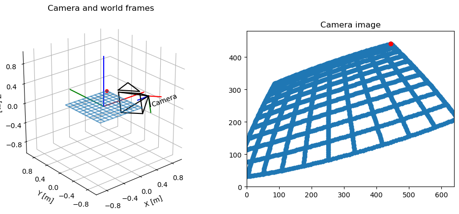
[3] NeRF의 Cam to World Matrix 이해하기
1. Blender vs. pytransform3d의 기본 좌표계 차이
-
Blender 기본축
- “Z축이 위”, “Y축이 전방”, “X축이 오른쪽” 형태로 씁니다.
- 또 Blender 카메라는 Z축의 음의 방향을 바라봅니다.
- 즉, Blender에서 export된
transform_matrix는 “이 카메라가 -Z를 보고 있다”는 전제 아래, 월드 공간에서 어떤 위치/회전을 가졌는지 표현합니다.
-
pytransform3d
- Blender 카메라와 달리 Z축의 양의 방향을 바라봅니다.
plot_camera는 “카메라의 optical axis가 +Z”일 때를 기본 전제로, 그 Frustum(사각뿔)을 그려주는 식입니다.
이렇게 서로 다른 축 정의가 섞이면,
Blender에서 “-Z로 바라보는” 카메라를 그대로 시각화했을 때
pytransform3d 입장에선 카메라가 정 반대의 후방을 바라보고있는 것처럼 그려집니다.
따라서 이를 해결하기 위해 X축을 기준으로 카메라를 180도 회전시키는 전처리 작업이 필요합니다.
2. 왜 시각화 라이브러리에서 이동과 회전 행렬만을 사용할까?
예를 들어 카메라 시각화(pytransform3d 등)에서는,
- “카메라가 어떤 방향을 보는지”를 일관된 오른손좌표계(RHC)로 표현해야
- 광학축(+z인지 -z인지)을 정확히 정하고, 뷰 프러스텀 등을 자연스럽게 그릴 수 있습니다.
그러나 반사 행렬)이 들어오면,
- “왼손좌표계”로 바뀌거나, 카메라 축이 뒤집히는 등
- 내부적인 로직(광학축 +z)과 충돌을 일으킵니다.
따라서 카메라의 위치를 고려할 때는 이동과 회전만을 허용하며,인 행렬은 시각화 라이브러리에서 사용할 수 없습니다. 그렇기 때문에 NeRF의 마지막 변환도
대신에 아래와 같은 행렬을 사용하는 것입니다.
3. 회전 행렬과 반사 행렬의 판별
3차원에서 “길이와 직각(orthonormal basis)”을 보존하는 정규직교 정변환(orthogonal transformation)은 크게 두 부류로 나뉩니다:
-
:
- 회전(Rotation) 만으로 설명되는 “올바른 회전(proper rotation)”.
- 공간의 방향(orientation)을 보존한다.
- 수학적으로(특수직교군)이라 부름.
-
:
- 축 뒤집기, 거울 반사, rotoreflection(회전+반사) 등을 포함하는 “부적절 회전(improper rotation)”.
- 공간의 방향(orientation)을 뒤집음.
-부분에 해당.
# Z축 t 평행이동
trans_t = lambda t : torch.Tensor([
    [1,0,0,0],
    [0,1,0,0],
    [0,0,1,t],
    [0,0,0,1]]).float()

# X축 파이 회전
rot_phi = lambda phi : torch.Tensor([
    [1,0,0,0],
    [0,np.cos(phi),-np.sin(phi),0],
    [0,np.sin(phi), np.cos(phi),0],
    [0,0,0,1]]).float()

# Y축 세타 회전
rot_theta = lambda th : torch.Tensor([
    [np.cos(th),0,-np.sin(th),0],
    [0,1,0,0],
    [np.sin(th),0, np.cos(th),0],
    [0,0,0,1]]).float()

# X축 반전, Y-Z 스왑
swap_mat = torch.Tensor([
    [-1, 0, 0, 0],
    [ 0, 0, 1, 0],
    [ 0, 1, 0, 0],
    [ 0, 0, 0, 1]
])
'''
swap_mat = torch.Tensor([
    [ 1, 0, 0, 0],
    [ 0, 0, 1, 0],
    [ 0, 1, 0, 0],
    [ 0, 0, 0, 1]
])
카메라의 이동을 다룰 때, 반사는 오른손 좌표계를 반전시켜 충돌을 일으킬 수 있으므로, 오직 이동과 회전만 고려한다.
그러나 X축 반전이 없는 위 행렬은 det = -1인 반사 행렬로, 연속된 회전 행렬로 분해할 수 없다. (연쇄 회전 행렬의 det = 1이다.)
따라서 어쩔 수 없이 X 축에 반전을 주는 것이다.
'''

'''
해당 함수에서 원본 코드에 있는 변수의 이름인 c2w를 그대로 사용하였지만, 여기서는 정 반대의 정보인 w2c(extrinsic matrix)를 구하기 위해 사용됩니다.
즉, 월드 좌표계에 곱하여 카메라 좌표계로 이동하는 행렬에 대한 정보가 담겨있습니다.
'''
def pose_spherical(phi, theta, radius):
    c2w_list = []

    # 중요! pytransfrom3d의 카메라는 Z축을 바라보고 있지만, blender dataset의 카메라는 -Z축을 바라보고 있으므로
    # 먼저 X축 기준으로 180도 회전시켜 두 카메라를 얼라인 해야 한다.
    c2w = rot_phi(180/180.*np.pi)
    c2w_list.append(c2w.clone())

    # 1) 평행이동
    c2w = trans_t(radius) @ c2w
    c2w_list.append(c2w.clone())  # clone()으로 복사

    # 2) rot_phi 곱
    c2w = rot_phi(phi/180.*np.pi) @ c2w
    c2w_list.append(c2w.clone())

    # 3) rot_theta 곱
    c2w = rot_theta(theta/180.*np.pi) @ c2w
    c2w_list.append(c2w.clone())

    # 4) 마지막 행렬 곱
    c2w = swap_mat @ c2w
    c2w_list.append(c2w.clone())

    return c2w_list  # 모든 단계를 반환 (리스트)


# 단순 시각화를 위한 카메라 내부 매트릭스 인자값 지정
intrinsic_matrix = np.array([
    [0.05, 0,    0.036/2.0],
    [0,    0.05, 0.024/2.0],
    [0,    0,    1]
])
sensor_size = np.array([0.036, 0.024])
virtual_image_distance = 1.0 # 뷰 프러스텀 크기


# pose_spherical로부터 단계별 c2w 가져오기
phi, theta, radius = -30, 90, 3
'''
phi의 값이 30이 아닌 -30인 이유도 swap_mat 때문이다.
'''
c2w_list = pose_spherical(phi, theta, radius)  # [torch.Tensor(4x4), ...]

fig = plt.figure(figsize=(9, 9))
ax = fig.add_subplot(111, projection='3d')

pt.plot_transform(ax=ax, A2B=np.eye(4), s=0.4, name="World")

for i, c2w_torch in enumerate(c2w_list):
    c2w_np = c2w_torch.numpy()  # pytransform3d는 np.array로 다룸

    # 좌표축 그리기 (원점+3축)
    ax = pt.plot_transform(
        A2B=c2w_np,  # (4x4) 카메라->월드 행렬
        ax=ax,
        s=0.2,        # 좌표축 스케일
        name=f"Step {i}"
    )

    # 카메라 프러스텀 그리기
    pc.plot_camera(
        ax=ax,
        cam2world=c2w_np,        # (4x4) 카메라->월드
        M=intrinsic_matrix,
        sensor_size=sensor_size,
        virtual_image_distance=virtual_image_distance,
        label=f"Step {i}",
        color="red",
        alpha=0.2
    )

# 보기 편하도록 뷰 설정: elev(위에서 내려보는 각도), azim(수평 회전)
ax.view_init(elev=5, azim=45)

# 카메라들이 너무 바깥이면 축 범위를 넉넉히 설정
ax.set_xlim([-3, 3])
ax.set_ylim([-3, 3])
ax.set_zlim([-3, 3])

# 3D 축 비율을 1:1:1로 맞추고 싶으면 pytransform3d의 set_3d_axes_equal 등을 사용할 수도 있음
# 여기서는 간단히 set_box_aspect 써도 됨 (matplotlib 3.3+)
ax.set_box_aspect((1,1,1))

plt.show()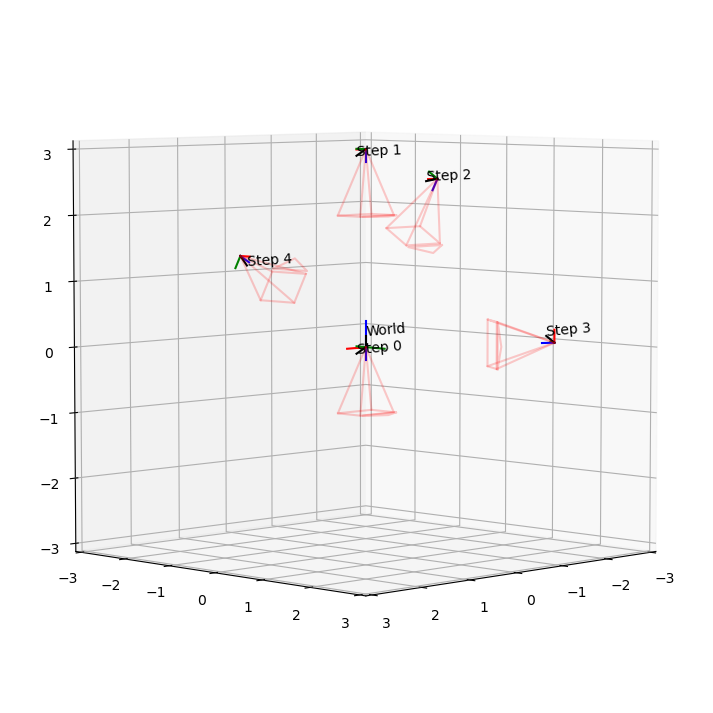
def render_frame(phi, theta, radius, filename):
    fig = plt.figure(figsize=(6, 6))
    ax = fig.add_subplot(111, projection='3d')
    virtual_image_distance = 1.0

    # pose_spherical로부터 단계별 c2w 가져오기
    c2w_list = pose_spherical(phi, theta, radius)  # [torch.Tensor(4x4), ...]

    pt.plot_transform(ax=ax, A2B=np.eye(4), s=0.4, name="World")

    for i, c2w_torch in enumerate(c2w_list):
        c2w_np = c2w_torch.numpy()  # pytransform3d는 np.array로 다룸

        # 좌표축 그리기 (원점+3축)
        ax = pt.plot_transform(
            A2B=c2w_np,  # (4x4) 카메라->월드 행렬
            ax=ax,
            s=0.2,        # 좌표축 스케일
            name=f"Step {i}"
        )

        # 카메라 프러스텀 그리기
        pc.plot_camera(
            ax=ax,
            cam2world=c2w_np,        # (4x4) 카메라->월드
            M=intrinsic_matrix,
            sensor_size=sensor_size,
            virtual_image_distance=virtual_image_distance,
            label=f"Step {i}",
            color="red",
            alpha=0.2
        )

    # 보기 편하도록 뷰 설정: elev(위에서 내려보는 각도), azim(수평 회전)


    # 카메라들이 너무 바깥이면 축 범위를 넉넉히 설정
    ax.set_xlim([-4, 4])
    ax.set_ylim([-4, 4])
    ax.set_zlim([-4, 4])

    # 3D 축 비율을 1:1:1로 맞추고 싶으면 pytransform3d의 set_3d_axes_equal 등을 사용할 수도 있음
    # 여기서는 간단히 set_box_aspect 써도 됨 (matplotlib 3.3+)
    ax.set_box_aspect((1,1,1))

    # ax.view_init(elev=30, azim=0) ################
    # ax.view_init(elev=0, azim=90)
    # ax.view_init(elev=90, azim=0)
    ax.view_init(elev=10, azim=45)

    plt.title(f"phi={phi:.1f}, theta={theta:.1f}, radius={radius:.1f}")
    # plt.savefig(filename)
    plt.savefig(filename, bbox_inches='tight', pad_inches=0.1)
    plt.close(fig)

def create_animation_gif():
    # 저장 폴더
    out_dir = "frames"
    os.makedirs(out_dir, exist_ok=True)

    # 예: phi는 고정(45), theta를 0부터 360까지 10도 간격으로 변환
    #    radius도 예를 들어 4로 고정
    phi = -30
    radius = 4

    # 이미지 저장용 리스트
    images = []

    for i in range(120):
        theta = i * 3
        filename = os.path.join(out_dir, f"frame_{i:03d}.png")
        # 1) 프레임 그려서 PNG로 저장
        render_frame(phi, theta, radius, filename)

        # 2) 저장된 PNG 이미지를 읽어서 images 리스트에 쌓기
        img = imageio.imread(filename)
        images.append(img)

    # GIF 만들기 (frames/animation.gif)
    gif_path = os.path.join(out_dir, "animation.gif")
    imageio.mimsave(gif_path, images, fps=30, loop = 0)  # fps=5 → 초당 5프레임

    print(f"GIF saved to {gif_path}")

create_animation_gif()
GIF saved to frames/animation.gif
phi를 -30도로 고정하고 theta를 움직였을 때, 최종 카메라의 궤적은 Z축을 중심으로 XZ평면을 바라보며 회전한다.
[4] 블렌더 데이터셋 살펴보기
Blender로 생성된 NeRF 데이터셋(예: transforms.json)에서 흔히 볼 수 있는 필드는 다음과 같습니다:
-
camera_angle_x- 카메라의 수평(Horizontal) 화각(Field of View, FOV) 을 의미합니다.
- 보통 라디안(radians) 단위로 표현되어, 예:
0.6911112070083618라면 약39.6°정도 (np.degrees(0.6911)≈ 39.6 ). - 이 값을 통해 “카메라 내부 파라미터”에서 초점거리(f)나 화면 크기, 화각 간의 관계를 계산할 수 있습니다.
-
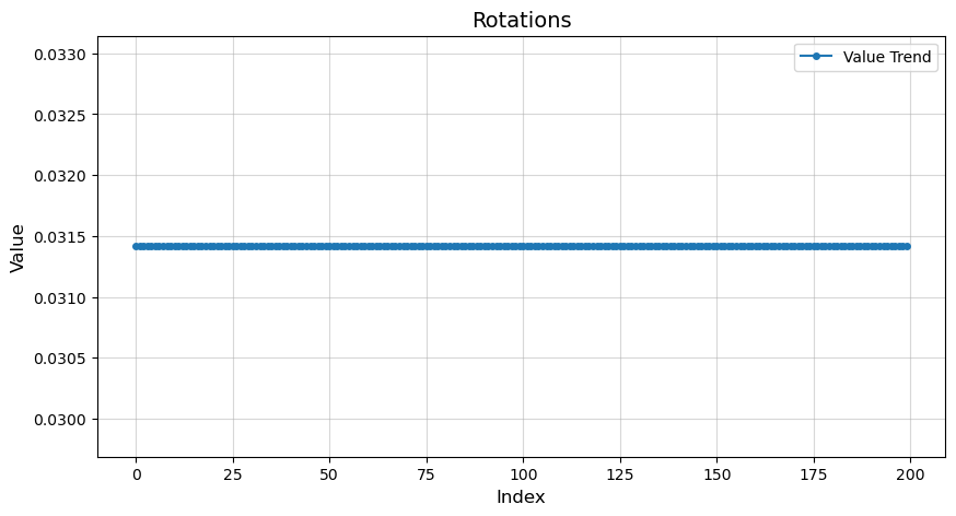
rotation- 각 프레임(또는 이미지)에 대응하는 회전값인데, NeRF 원본 코드에서는 주로 동영상이나 영상을 만들 때 카메라를 부드럽게 회전(interpolate)시키기 위해 사용됩니다.
- 예컨데,
rotation = 0.0125663이런 값은 한 프레임에서 다음 프레임으로 넘어갈 때의 회전 정도(에니메이션용)를 가리키는 경우가 많습니다.- 예: 2π를 약 6.28로 보면, 0.012566...은 2π/500 정도에 해당하므로, “프레임 간 아주 미세한 회전”을 나타낼 수 있습니다.
- 실제로 학습에서 “카메라를 회전시켜 가며 이미지 렌더링” 할 때 이 값을 이용해 프레임 사이를 보간하거나, 동영상 만들 때 스텝 크기로 활용합니다.
-
transform_matrix- 4×4 동차 변환 행렬로, 카메라 좌표계 → 월드 좌표계 변환(또는 그 반대)을 나타냅니다.
- Blender 등에서 내보낼 때, 보통 “카메라가 어떤 위치(R, t)에 있는지”를 직렬화하여 JSON으로 저장하는데, 이 행렬이 카메라의 외부 파라미터(Extrinsics) 역할을 합니다.
- 예: 이런 형태로, 회전(3×3)과 평행이동(3×1)이 합쳐진 형태입니다.
요약
camera_angle_x: 카메라의 가로 화각(FOV), 라디안 단위.rotation: 주로 프레임 간 회전 애니메이션을 위한 작은 각도(혹은 스텝) 정보를 저장. (학습 시에는 크게 쓰이지 않고, 영상/회전 경로 보간 등에 사용)transform_matrix: 카메라의 외부 파라미터(Extrinsics)로서, 카메라에서 월드로(또는 그 반대) 가는 변환 행렬을 4×4 동차 좌표계로 표현한 것.
import json# data practice
_datadir = './data/nerf_synthetic/lego'
with open(os.path.join(_datadir, 'transforms_test.json'), 'r') as fp:
meta = json.load(fp)
print(meta['camera_angle_x'])
print(meta['frames'][0])
print(meta['frames'][0]['transform_matrix'])
rotations = []
transform_matrixes = []
print(len(meta['frames']))
for i in range(len(meta['frames'])):
rotations.append(meta['frames'][i]['rotation'])
transform_matrixes.append(meta['frames'][i]['transform_matrix'])0.6911112070083618
{'file_path': './test/r_0', 'rotation': 0.031415926535897934, 'transform_matrix': [[-0.9999999403953552, 0.0, 0.0, 0.0], [0.0, -0.7341099977493286, 0.6790305972099304, 2.737260103225708], [0.0, 0.6790306568145752, 0.7341098785400391, 2.959291696548462], [0.0, 0.0, 0.0, 1.0]]}
[[-0.9999999403953552, 0.0, 0.0, 0.0], [0.0, -0.7341099977493286, 0.6790305972099304, 2.737260103225708], [0.0, 0.6790306568145752, 0.7341098785400391, 2.959291696548462], [0.0, 0.0, 0.0, 1.0]]
200# print(rotations)
# print(transform_matrixes[0])fig = plt.figure(figsize=(9, 9))
ax = fig.add_subplot(111, projection='3d')
pt.plot_transform(ax=ax, A2B=np.eye(4), s=0.4, name="World")
# pytransform3d와 blender dataset의 카메라 얼라인(X축 180도 회전)
fix_mat = np.array([
[1, 0, 0, 0],
[0, -1, 0, 0],
[0, 0, -1, 0],
[0, 0, 0, 1]
])
# 블렌더 데이터셋 중 하나의 transform_matrix
c2w_list = [[-0.9999999403953552, 0.0, 0.0, 0.0],
[0.0, -0.7341099977493286, 0.6790305972099304, 2.737260103225708],
[0.0, 0.6790306568145752, 0.7341098785400391, 2.959291696548462],
[0.0, 0.0, 0.0, 1.0]]
c2w_np = np.array(c2w_list) @ fix_mat
# 좌표축 그리기 (원점+3축)
ax = pt.plot_transform(
A2B=c2w_np, # (4x4) 카메라->월드 행렬
ax=ax,
s=0.2, # 좌표축 스케일
# name=f"Step {i}"
)
# 카메라 프러스텀 그리기
pc.plot_camera(
ax=ax,
cam2world=c2w_np, # (4x4) 카메라->월드
M=intrinsic_matrix,
sensor_size=sensor_size,
virtual_image_distance=virtual_image_distance,
# label=f"Step {i}",
color="red",
alpha=0.2
)
# 보기 편하도록 뷰 설정: elev(위에서 내려보는 각도), azim(수평 회전)
ax.view_init(elev=10, azim=45)
# 카메라들이 너무 바깥이면 축 범위를 넉넉히 설정
ax.set_xlim([-4, 4])
ax.set_ylim([-4, 4])
ax.set_zlim([-4, 4])
# 3D 축 비율을 1:1:1로 맞추고 싶으면 pytransform3d의 set_3d_axes_equal 등을 사용할 수도 있음
# 여기서는 간단히 set_box_aspect 써도 됨 (matplotlib 3.3+)
ax.set_box_aspect((1,1,1))
plt.show()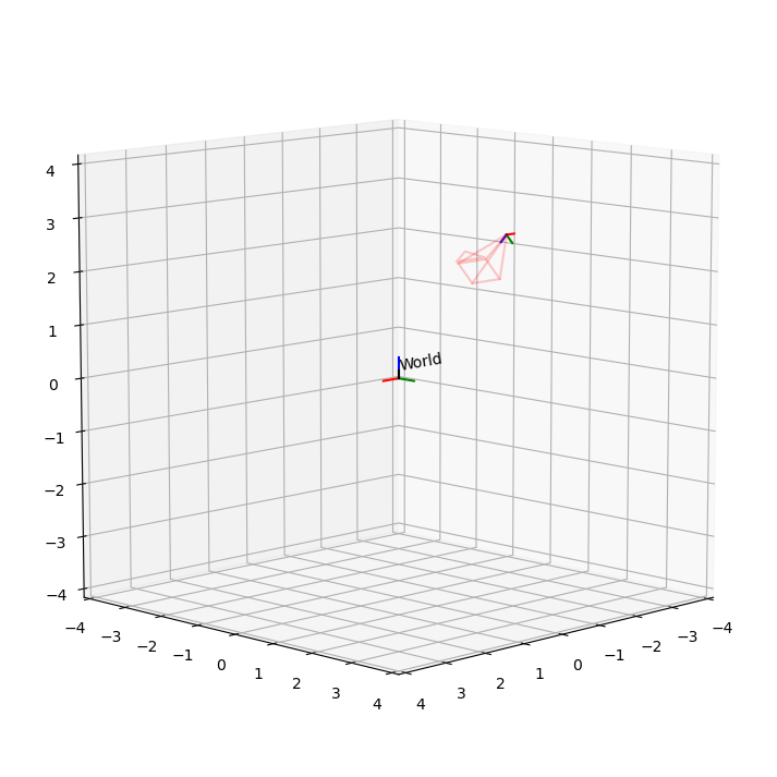
# pytransform3d와 blender dataset의 카메라 얼라인(X축 180도 회전)
fix_mat = np.array([
    [1,  0,  0, 0],
    [0, -1,  0, 0],
    [0,  0, -1, 0],
    [0,  0,  0, 1]
])

virtual_image_distance = 0.5
fig = plt.figure(figsize=(9, 9))
ax = fig.add_subplot(111, projection='3d')

pt.plot_transform(ax=ax, A2B=np.eye(4), s=0.4, name="World")

for i, c2w_list in enumerate(transform_matrixes):
    if i % 5 == 0:
        # c2w_np = np.array(c2w_list) # pytransform3d는 np.array로 다룸
        c2w_np = np.array(c2w_list) @ fix_mat

        # 좌표축 그리기 (원점+3축)
        ax = pt.plot_transform(
            A2B=c2w_np,  # (4x4) 카메라->월드 행렬
            ax=ax,
            s=0.2,        # 좌표축 스케일
            name=f"Step {i}"
        )

        # 카메라 프러스텀 그리기
        pc.plot_camera(
            ax=ax,
            cam2world=c2w_np,        # (4x4) 카메라->월드
            M=intrinsic_matrix,
            sensor_size=sensor_size,
            virtual_image_distance=virtual_image_distance,
            label=f"Step {i}",
            color="red",
            alpha=0.2
        )

# 보기 편하도록 뷰 설정: elev(위에서 내려보는 각도), azim(수평 회전)
ax.view_init(elev=30, azim=45)

# 카메라들이 너무 바깥이면 축 범위를 넉넉히 설정
ax.set_xlim([-3, 3])
ax.set_ylim([-3, 3])
ax.set_zlim([-3, 3])

# 3D 축 비율을 1:1:1로 맞추고 싶으면 pytransform3d의 set_3d_axes_equal 등을 사용할 수도 있음
# 여기서는 간단히 set_box_aspect 써도 됨 (matplotlib 3.3+)
ax.set_box_aspect((1,1,1))

plt.show()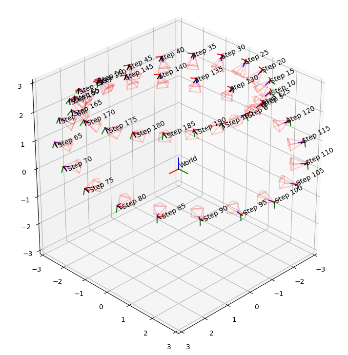
plt.figure(figsize=(10, 5))
plt.plot(rotations, marker='o', linestyle='-', markersize=4, label='Value Trend')
plt.title("Rotations", fontsize=14)
plt.xlabel("Index", fontsize=12)ㄴ
plt.ylabel("Value", fontsize=12)
plt.grid(alpha=0.5)
plt.legend()
plt.show()