Chapter 4: The Processor [First-Half]
• Building a datapath.• Pipeline. • Hazards.
Instruction Execution
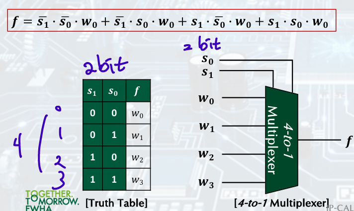
MUX: Multiplexer
4-to-1
+)Design Control Example p10
Logic Design Basics
information encoded in binary: 0, 1, multi-bit data encoded in multi-wire buses
-
Combinational element: operate on data, ALU, multiplexer
-
Sequential (state) elements: store information, output depends on previous behavior on circuit too
Edge-Trigered D Flip-Flop: Q가 Clk 단위로 D=Qm을 따라감
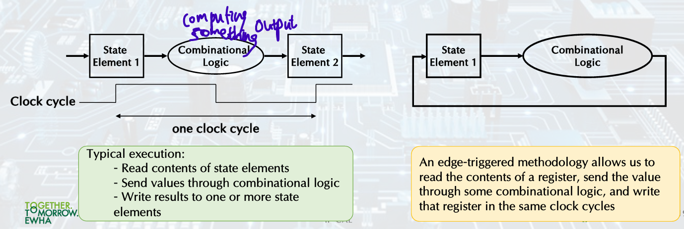
Clocking Methodology
Combinational logic transforms data during clock cycles.
• Between clock edges.
• Input from state elements, output to state element.
• Longest delay determines clock period.
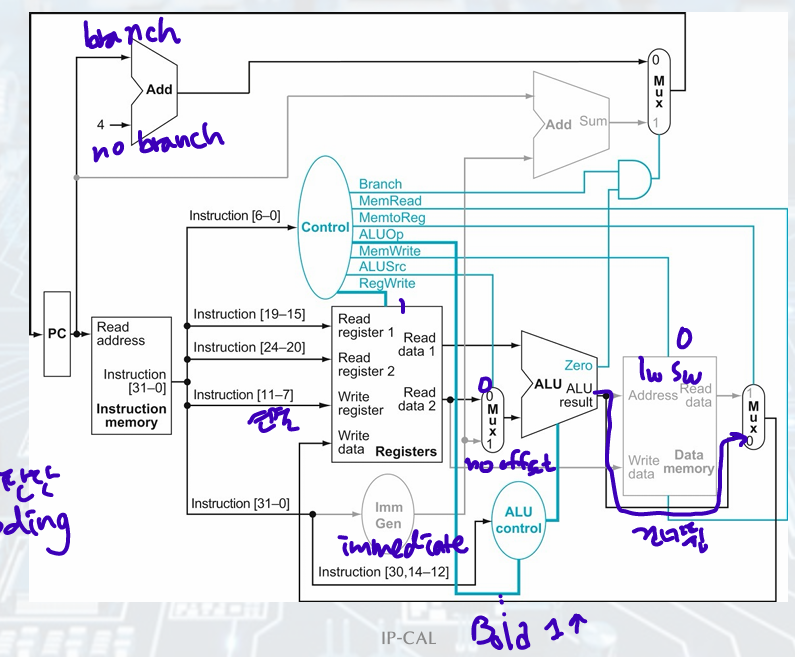
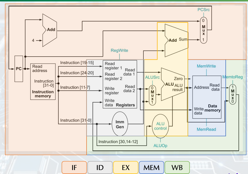
1. Buildiing a Datapath
Full Datapath
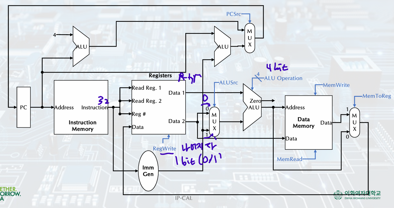
Fetching Instructions
2 state elements:
Instruction memory
Program counter(PC): The register containing the address of istruction, +4
(PC, ADD ALU, instruction Memory)
R-Format Instruction
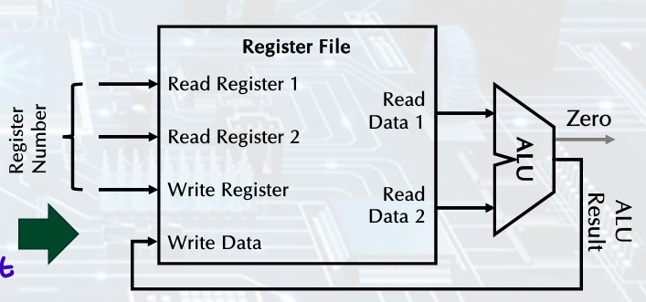
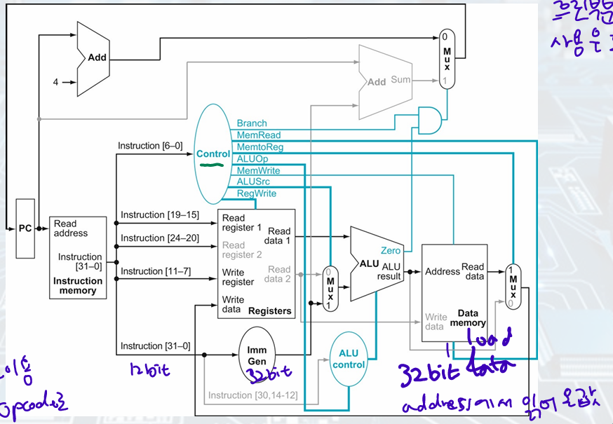
- Register file:
state element consisting of set of registers, registers can be read and written by supplying a register number - R-format instructions:
Two data words read from the register file, one data word written, 3 register operand
- R-Format: ALU Operations
# of bits register 5bit, data 32bit
Load/Store Instruction
store: value, read from the Register File during decode, written to the Data Memory
load: value, read from the Data Memory, written to the Register File
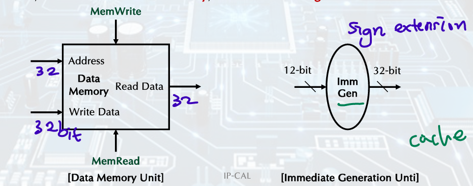
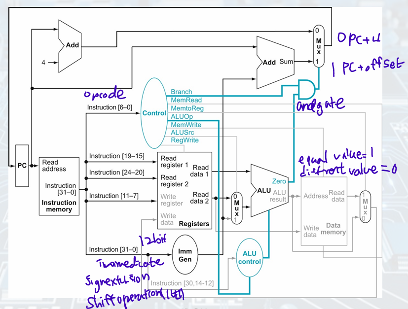
- Immediate Generation Unit
sign-extend 12bit offset field in the instruction /to 32bit signed value(including shift left 1; increased range, ch3 참고), load, store, branch
음수고려 필요
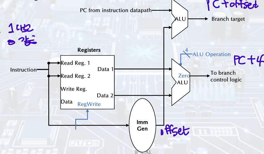
Branch Implementation
- read register operands
Compare operands
Calculate target adress:
if branch is taken, target address becomes new PC = (Sign-extended offset field<<1) + PC
else: PC + 4 - The branch datapath operations:
Compute the branch target address
Compare the register contents
+) The first-cut data path does an instruction in one clock cycle.
Use multiplexers where alternate data sources are used for different instructions.
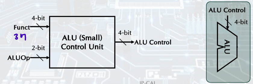
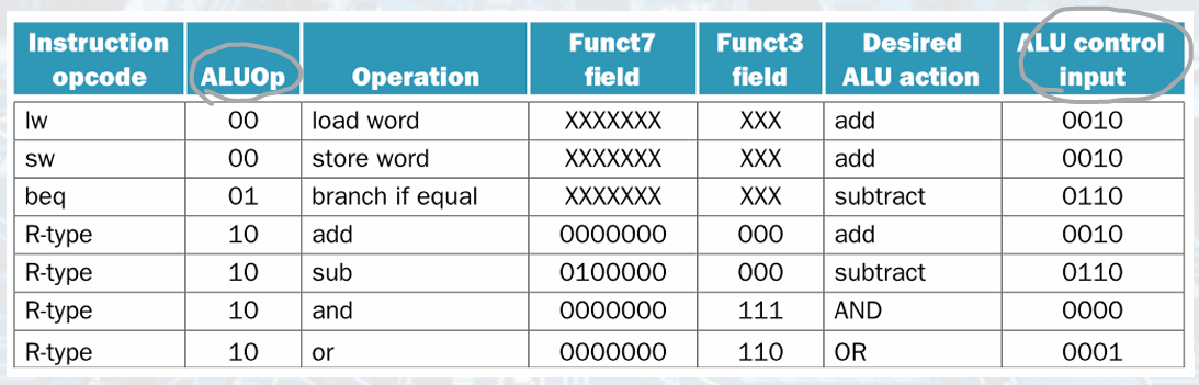
ALU Control
instruction(function field) 4bit, control(ALUOp) 2bit- ALU Control Unit 4bit- ALU
2. Designing Control Unit
R-Type Instruction
• Steps:
1. The instruction is fetched, and the PC is incremented.
2. Two registers, x2 and x3 are read from the register file, and the main control unit computes the setting of the control lines during this step.
3. The ALU operates on the data read from the register file, using the function code to generate the ALU function.
4. The results from the ALU are written into the register (x1) in the register file.
=> instruction fetched(PC+4), read 2 registers and set main control, ALU, write result into register
Load Instruction
• Steps:
1. An instruction is fetched from the instruction memory, and the PC is incremented.
2. A register (x2) value is read from the register file.
3. The ALU computes the sum of the value read from the register file and the sign-extended 12 bits of the instruction (offset).
4. The sum from the ALU is used as the address for the data memory.
5. The data from the memory unit is written into the register file (x1).
=> instruction fetched, read a register from register file, ALU(value+offset), result used as address for data memory, write data from the memory unit into register file
Branch-on-Equal Instruction
• Steps:
1. An instruction is fetched from the instruction memory, and the PC is incremented.
2. Two registers, x1 and x2, are read from the register file.
3. The ALU subtracts one data value from the register file. The value of PC is added to the sign-extended, 12 bits of the instruction (offset) left shifted by one; the result is the branch target address.
4. The Zero status information from the ALU is used to decide which adder result to store in the PC.
=> instruction fetched, read 2 registers,
ALU (PC+offset)
Finalizing Control
Performance issus
The longest delay determines the clock period.
• Critical path: load instruction.
• Instruction memory à register file à ALU à data memory à register file
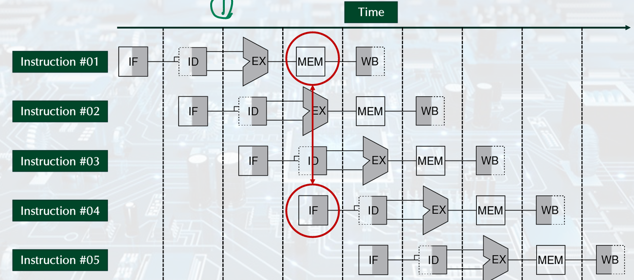
3. Pipelining
Steps in Executing RISC-V
Five stages, one step per stage.
• IF: Instruction fetch from memory.
• ID: Instruction decode & register read.
• EX: Execute operation or calculate address.
• MEM: Access memory operand.
• WB: Write result back to register.
Ideal Speedup
이상적임, 현실은 아님
Increasing instruction throughput, decreasing the execution time of an individual instruction
Time between Insructions_pipelined = (Time between Instructions_nonpipelined) / (Number of stages)
+) Datapath for RISC-V
Hazards
Limits to pipelining: Hazards prevent next instruction from executing during its designated clock cycle.
1. Structural hazard
: a required resource is busy
require seqerate instrcution and data memories or caches
load/store, instruciton fetch do data access to same memory
- Single Memory
solution: Two memory structures for Instruction and Data.
- Registers (WB, ID in 1,4)
solution: introduce convention
• always Write to registers during the first half of each clock cycle.
• always Read from Registers during the second half of each clock cycle.
• Result: can perform read and write during the same clock cycle
(as register access is very fast)
=> write first, read next
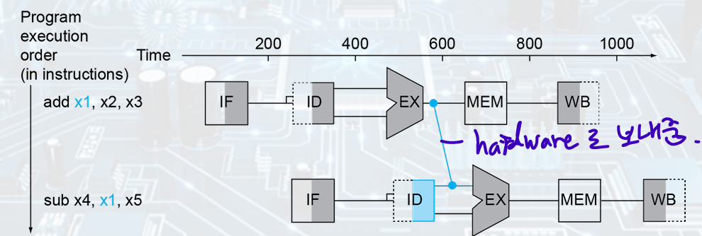
2. Data hazard
: Need to wait for previous instruction to complete its data read/write
add x1 sub x1
- Solution:
• As soon as the ALU creates the sum for the add, we can supply it as input for the subtract. (Forwarding)
• Forwarding or bypassing: Adding extra hardware to retrieve the missing item early from the internal resources.
- 뒤에서 앞으로 가야되면 Bubble 넣기; MEM output -bubble- EX input
- Code Scheduling to avoid stalls(bubble)
3. Control hazard
: Deciding on control action depends on previous instruction
beq x1,x2,offset
Wait until branch outcome is determined before fetching the next instruction.
- Solution: Branch Prediction 안나올듯
predict branches will be untake, if taken stall, restart pipeline
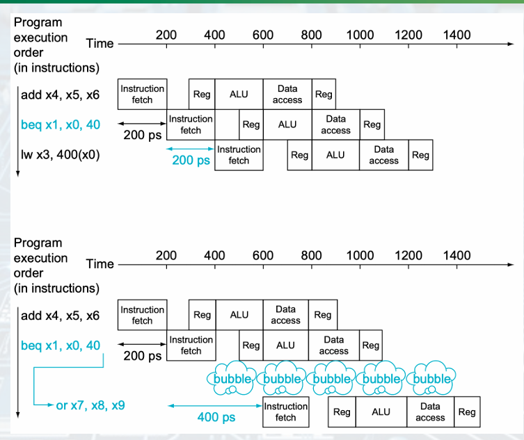
ALU - bubble - Istruction fetch
Dynamic branch prediction: using the past taken or untaken to predict the future 90% accuracy