Chapter 4. The Processor (2)
A Pipelined Datapath
5 Stages:
• IF: Instruction fetch.
• ID: Instruction decode and register file read.
• EX: Execution or address calculation.
• MEM: Data memory access.
• WB: Write back.
During any single clock cycle, Up to 5 instructions will be in execution
Instruction Flow
move from left to right
Two exceptions:
• The write-back stage: Placing the result back into the register file in the middle of the data path.
• Selection of the next value of the PC: Choosing between the incremented PC and the branch address from the MEM stage.
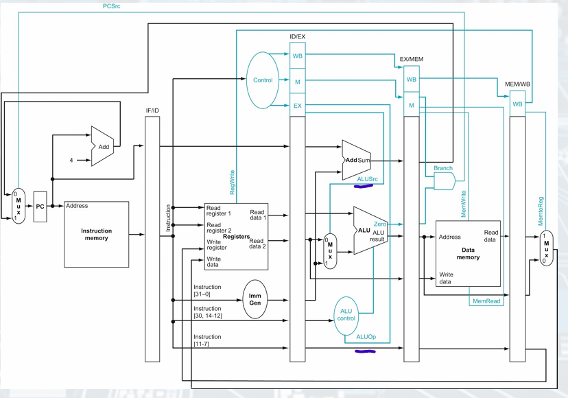
Datapath with Pipeline Registers
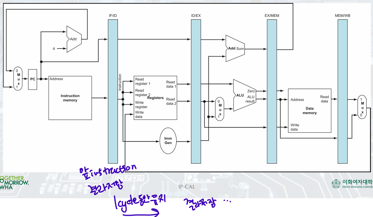
Load Example
-
Instruction Fetch(IF):
Using address in the PC, read the instruction from memory
place incremented PC address and instruction in the IF/ID pipeline register
don't know the type of instruction
=()read instruction/ place PC+4, instruction(IF/ID pipeline register) -
Instruction Decode(ID):
Instruction portion of the IF/ID pipeline register supplies the immediate field and the register numbers to read.
All three values are stored in the ID/EX pipeline register along with the incremented PC address.
= (IF/ID pipeline register) read instruction/ store immediate, register values + with PC address (ID/EX pipeline register) -
Instruction Execution(EX):
The load instruction reads the contents of register 1 and the sign-extended immediate from the ID/EX pipeline register and adds them using the ALU.
The sum is placed in the EX/MEM pipeline register.
= (ID/EX) read register data, sign-extended immediate-ALU-result is placed (EX/MEM) -
Memory Access(MEM):
(EX/MEM) using address, read data memory, load data into (MEM/WB) -
Write-Back(WB):
(MEM/WB) read data/ write it into (register file)
Corrected Pipelined Datapath
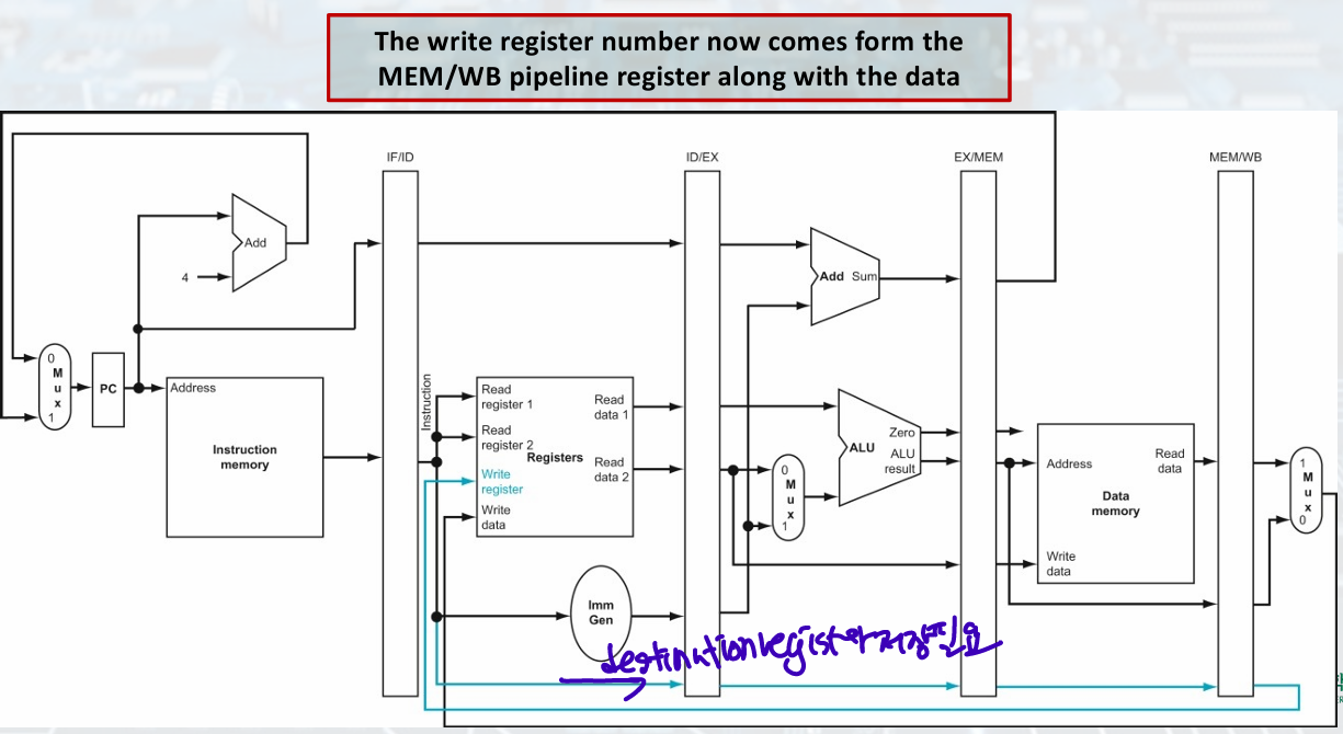
load must pass write register number(destination) from ID/EX to MEM/WB for WB stage
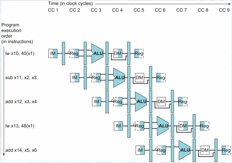
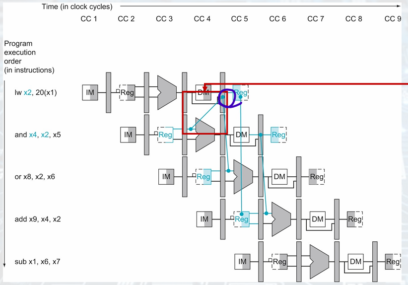
Graphically Representing Pipelines
Multi-clock-cycle pipeline
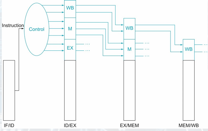
Pipelined Control
The pipeline registers are also written during each clock cycle.
Each control line is associated with a component active in only a single pipeline stage.
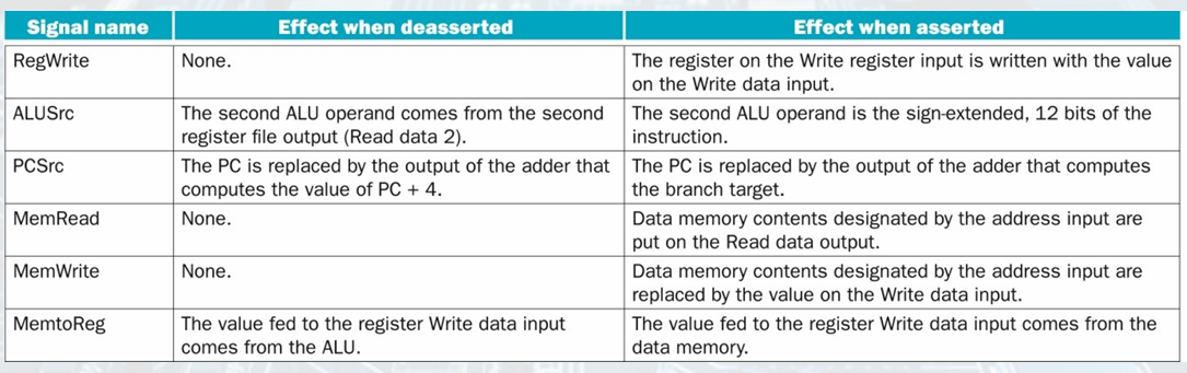
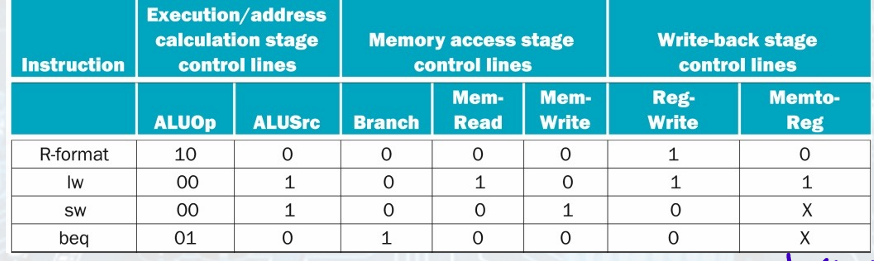
Implementation of Control Signals
setting the control lines to the values in each
stage for each instruction.
• The simplest way is to extend the pipeline registers to include control information.
• We can create the control information during instruction decode.
Hazards
Data Hazards
: Need to wait for previous instruction to complete its data read/write
sub x2... sw ...x2
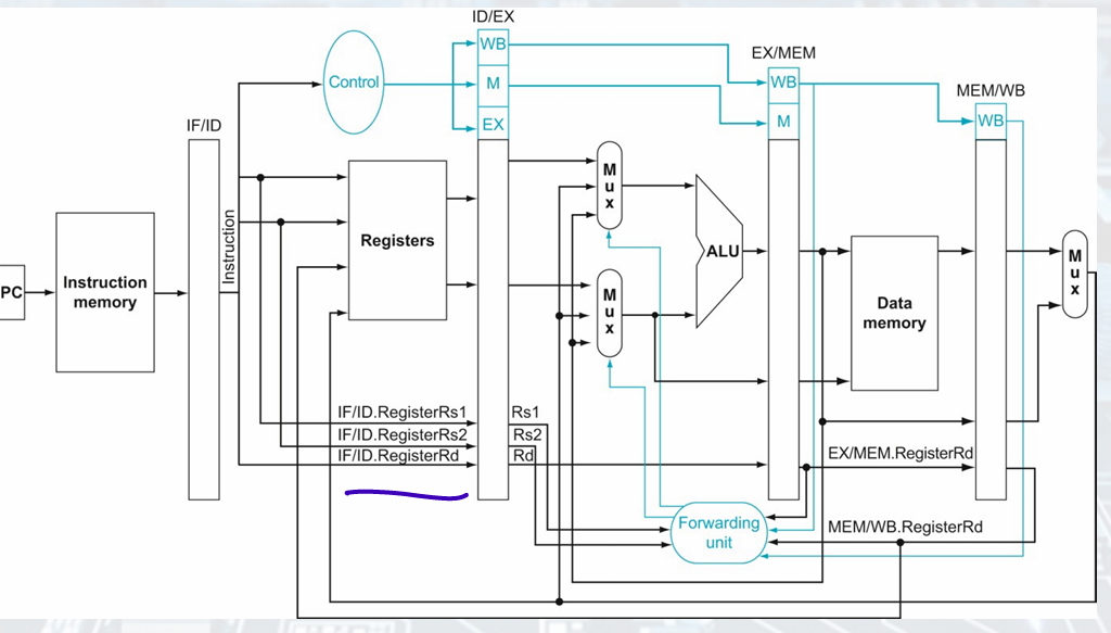
- Solution: forwarding
we can take the inputs to the ALU from any pipeline register by adding multiplexers to the input of the ALU and with the proper controls
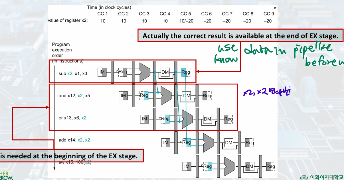
result is available after EX
it is needed in EX stage
-
Further Conditions
: check RegWrite signal (WB control field during EX, MEM stages) if instruction write registers
EX/MEM.REgisterRd 0, MEM/WB.RegisterRd 0 -
with Forfwarding
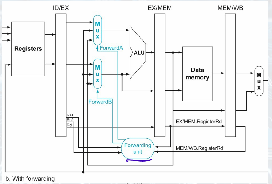
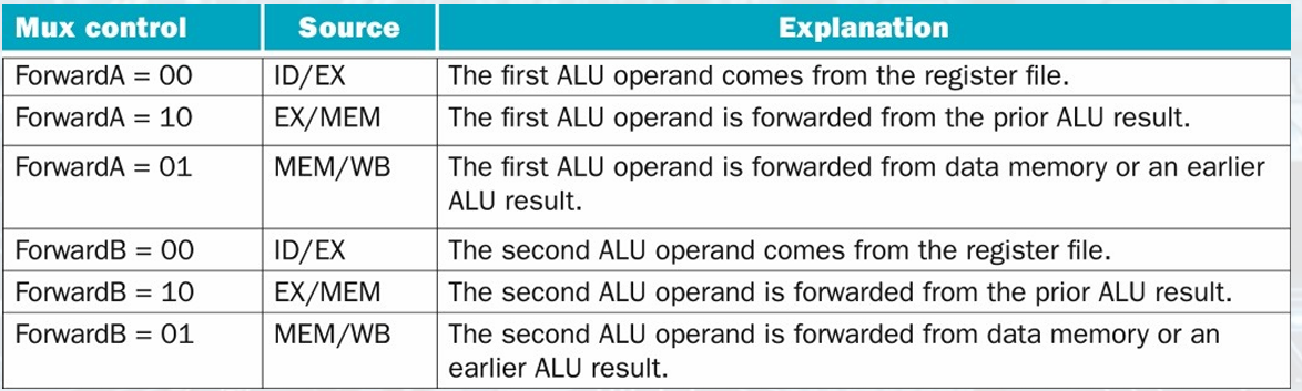
EX Hazard(Forwarded from EX/MEM)
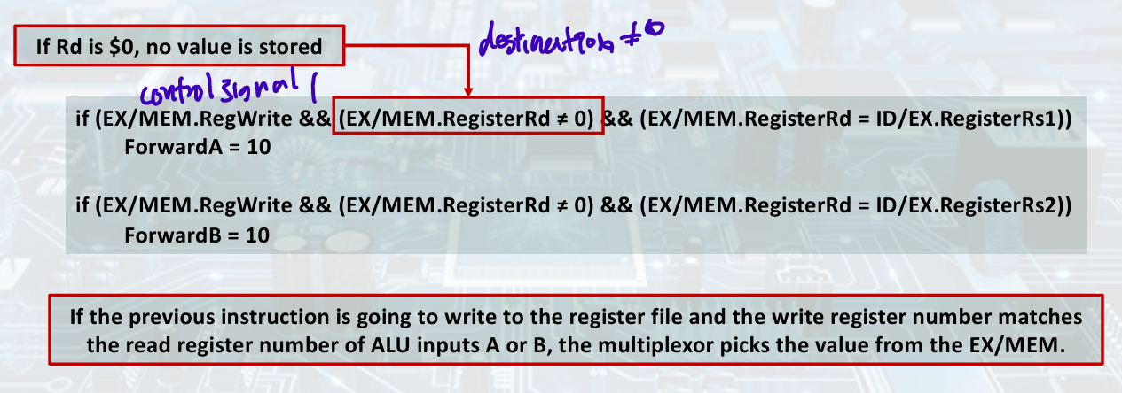
If the previous instruction is going to write to the register file and the write register number matches the read register number of ALU inputs A or B, the multiplexor picks the value from the EX/MEM.
= write, write and read register num same, multiplexor pick from EX/MEM
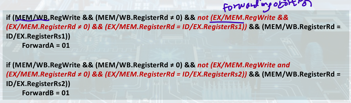
One complication: Potential data hazards between result of WB, MEM, source operand in ALU
MEM Hazard (with Corrections)
- double data hazard
add x1,x1,x2
add x1,x1,x3
add x1,x1,x4
'EX Hazard' forwarding 안하는 경우
- Datapath with Forwarding
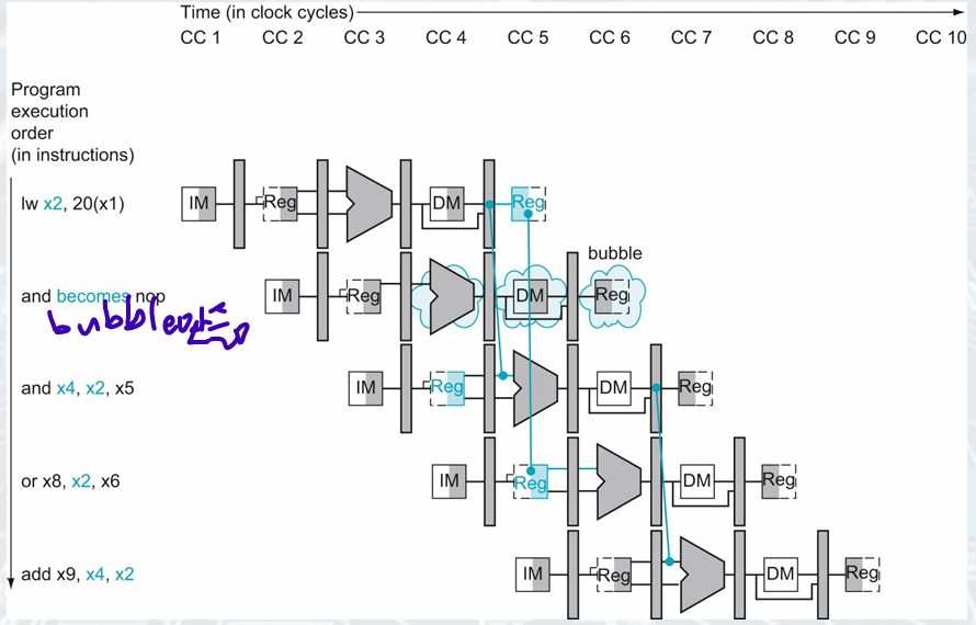
Load-use Data Hazard
Combining with load(result is in MEM/WB), something must stall the pipeline
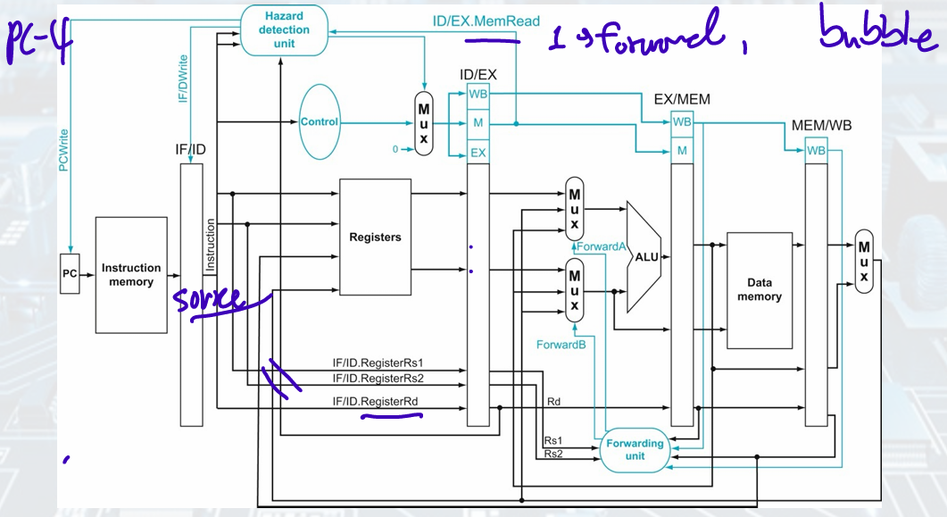
Condition:
if (ID/EX.MemRead && ID/EX.RegisterRd ≠ 0 &&((ID/EX.RegisterRd = IF/ID.RegisterRs1) || (ID/EX.RegisterRd = IF/ID.RegisterRs2)))
stall the pipeline
When ID is stalled, IF is also stalled
- NOP: No Operation
The EX, MEM, WB control fields of the ID/EX pipeline register to 0
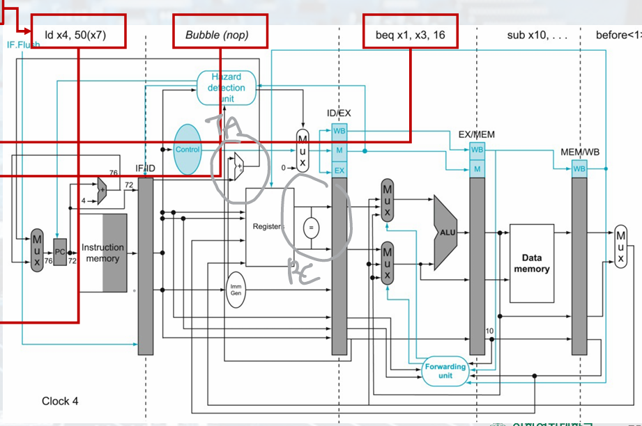
- Datapath with Hazard Detection
Control Hazard
If branch outcome determined in MEM
Wait until branch outcome is determined before fetching the next instruction.
Reducing Branch Delay
Move hardware to determine outcome to ID stage.
• Target address adder. // PC; orgPC + imm*2
• Register comparator.
- Datapath for Control Hazard(Branch taken)
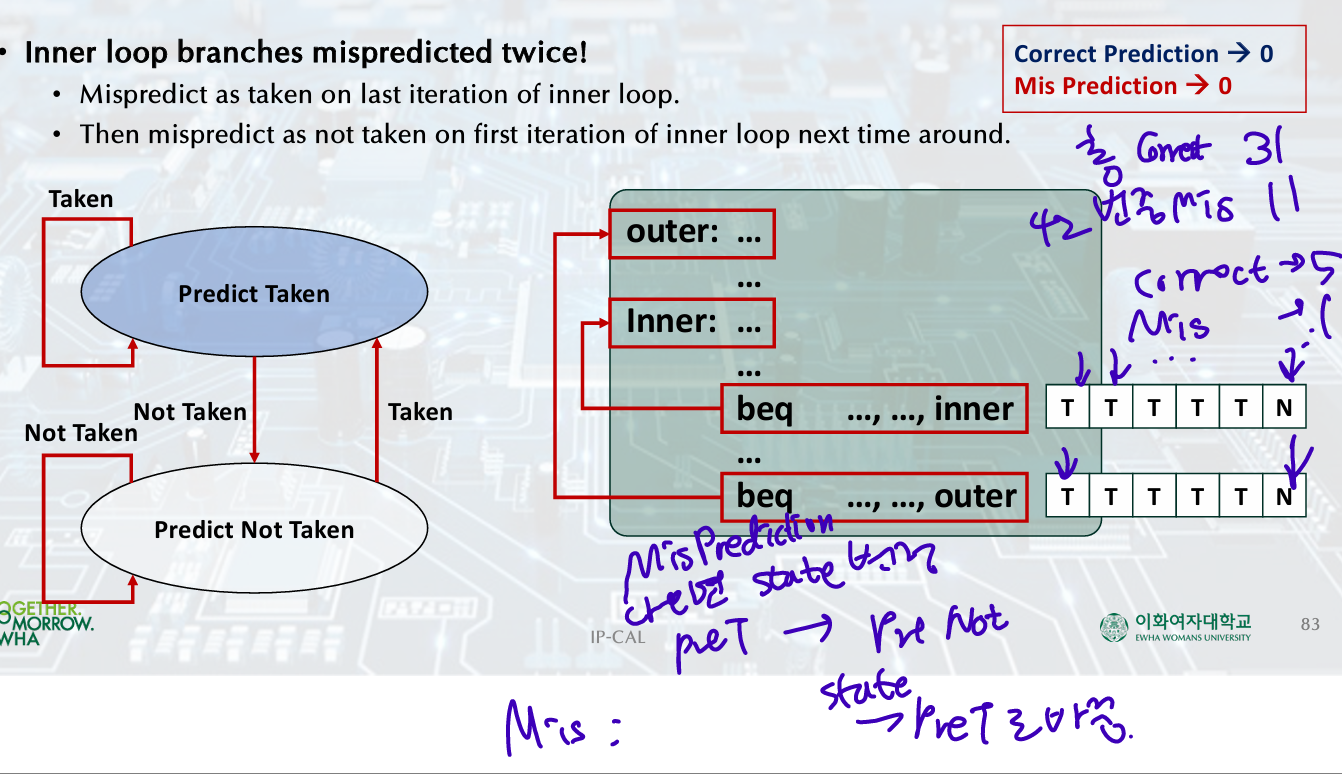
Dynamic Branch Prediction
To execute a branch,
• Check table, expect the same outcome.
• Start fetching from fall-through or target.
• If wrong, flush pipeline and flip prediction.
- 1-Bit Predictor: Shortcoming
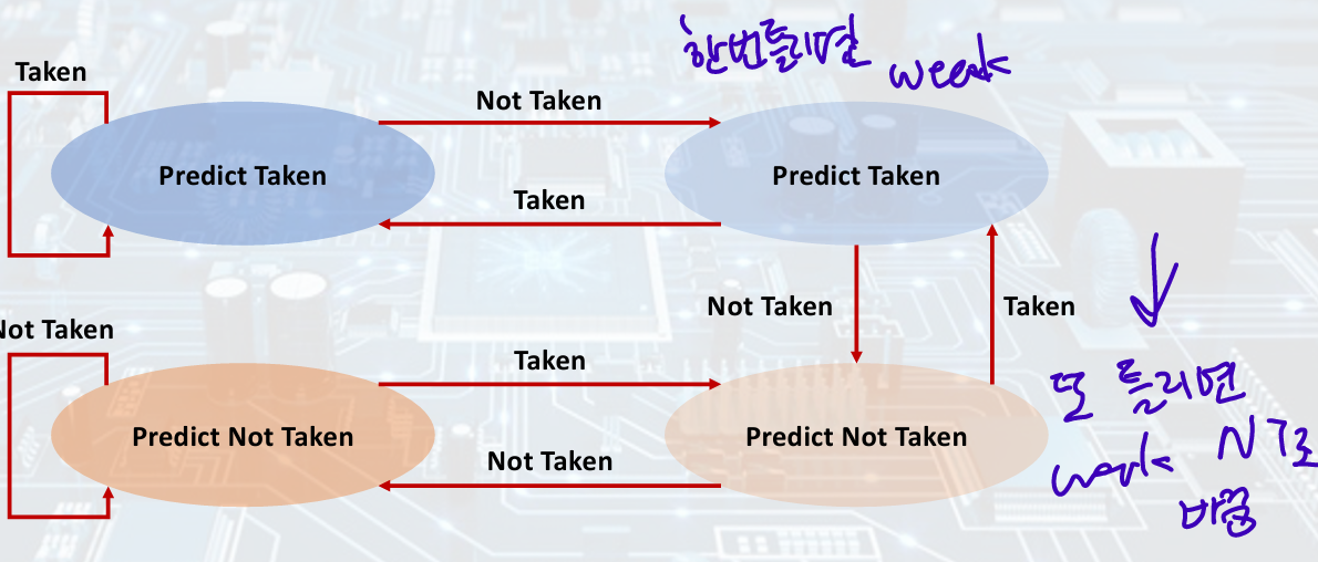
- 2-Bit Predictor
Calculating the Branch Target
1-cycle penalty for a taken branch,
Branch target buffer,
• Cache of target addresses.
• Indexed by PC when instruction fetched.
If hit and instruction is branch predicted taken, can fetch target immediately.