Summary
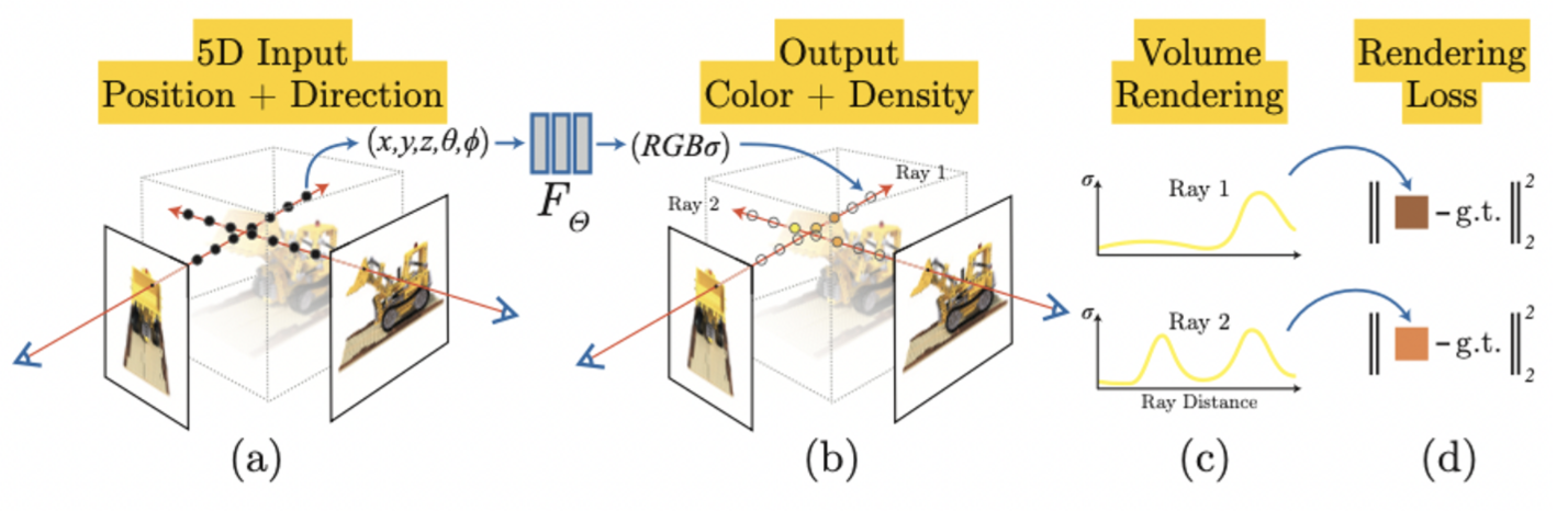
Input : spatial location (x, y, z), viewing direction (θ, φ) (5D coordinate)
- Spatial Position
- : xyz coordinate
- Viewing Direction
- : camera position
output : volume density, view-dependent emitted radiance
- Volume Density map
- xyz coordinate to opaque
- Color Radiance map
- xyz coordinate, camera position to RGB Color
After getting radiance output, process volume rendering to build motion
What is Neuiral Radiance Field
Approximate continuous 5D scene representation with an MLP network and optimaize weight to map from each input 5D coordinate to its corresponding volume density and directional emitted vector.
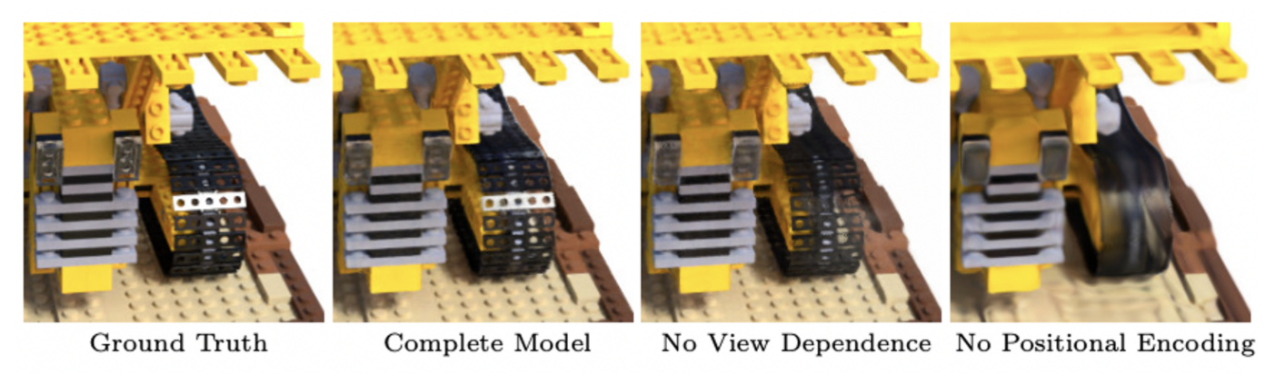
Positional Encoding
Neural network is universal function approximators.
That deep networks are biased towards learning lower frequency functions. Additionally, it also known as higher dimensional space using high frequency functions. So reformulating as a composition of , is a mapping from into a higher dimensional space , and is still simply a regular MLP.
This function is applied separately to each of the three coordinate values in . In this paper, for , for . This Process helps MLP network to learn more high dimensional space easily to approximate higher frequency function. It means, more detailed representation can be adapted.
Hierarchical Volume Sampling
There are a lot of free space and occluded regions that don’t contribute to the rendered image. So, need special method that sampling radiance point more efficiently. Paper propose a hierarchical representation that increases rendering efficiency by allocating samples proportionally to ehir expected effect on the final rendering.
Paper optimizes two networks. One is coarse, other one is fine. First, sample locations using stratified sampleing, and evaluate the coarse network at these locations. After evaluate network, produce a more informed sampling where samples are biased towards the relevant parts of the volume.
Rewrite alpha compositioned color from the coarse network as a weighted sum of all sampled colors . And sample a second set of locations from this distribution using inverse transform sampling. Evaluate “fine” network at union of the first and second set of samples. It is similar as importance sampling.

So Input is which is 3(coordinate) 2(cos / sin space) 10 (L), to 256 channel. Each black arrow is ReLU process. After finishing 4th layer, concat term. An additional layer outputs the volume density and 256 dimensional feature vector. This feature vector is concatencted with the positional encoding of the input viewing direction and is processed by and additional ReLU layer with 128 channels.
How to Rendering Volume from Radience?
- how to build 3D Image from this output?
- express previous sum of opaque to to
- ** express opaque at spatial point . It interpreted as the differential probability of a ray terminating at infinitesimal particle at location
- , d is viewing direction, o is starting point?
- express color at specific point consider viewing direction
- express previous sum of opaque to to
- Change quadrature to our discrete method
- express previous sum of opaque to to
- express previous sum of opaque to to
Loss
The paper use COLMAP package to estimate parameters for real data. Each optimization iteration, authors randomly sample a batch of camera rays from the set of all pixels in the dataset, and then follow the hierarchical sampling to query samples from the coarse, samples from fine network.
Loss is total squared error between rendered and true pixel colors for both networks.
where is the set of rays in each batch. In this experiment, , so all parameters are .