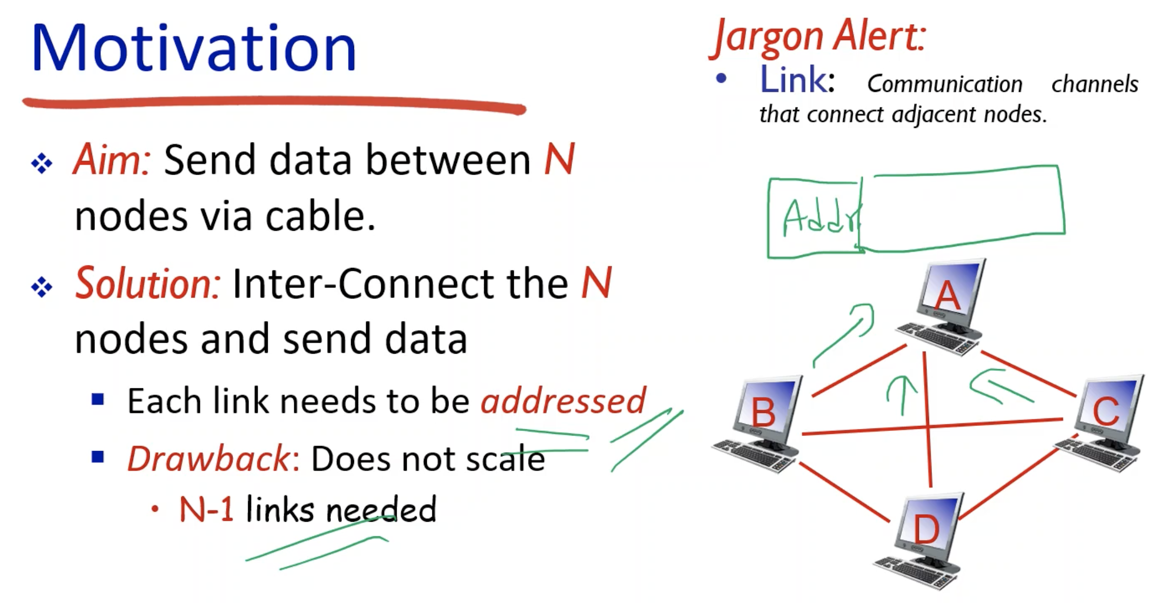
- To send data between N nodes, each link needs to be addressed, meaning that each node should know where the message is coming from and where to send to.
- The link above does not scale.
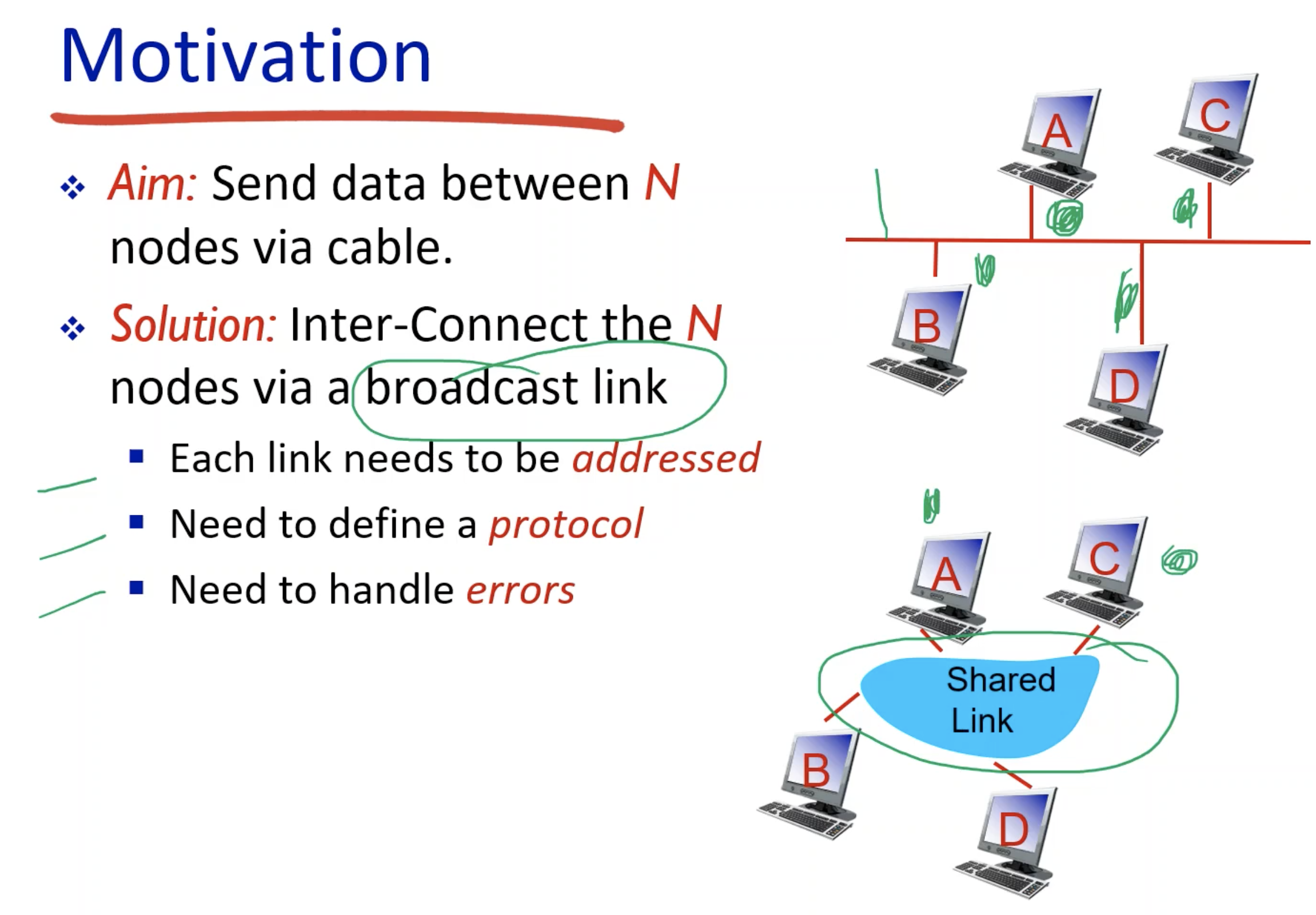
- Need for a protocol: there needs to be a set of rule for when and how the nodes can talk or transmit.
- How do we recover from collisions - two or more nodes trying to use the broadcasting medium?
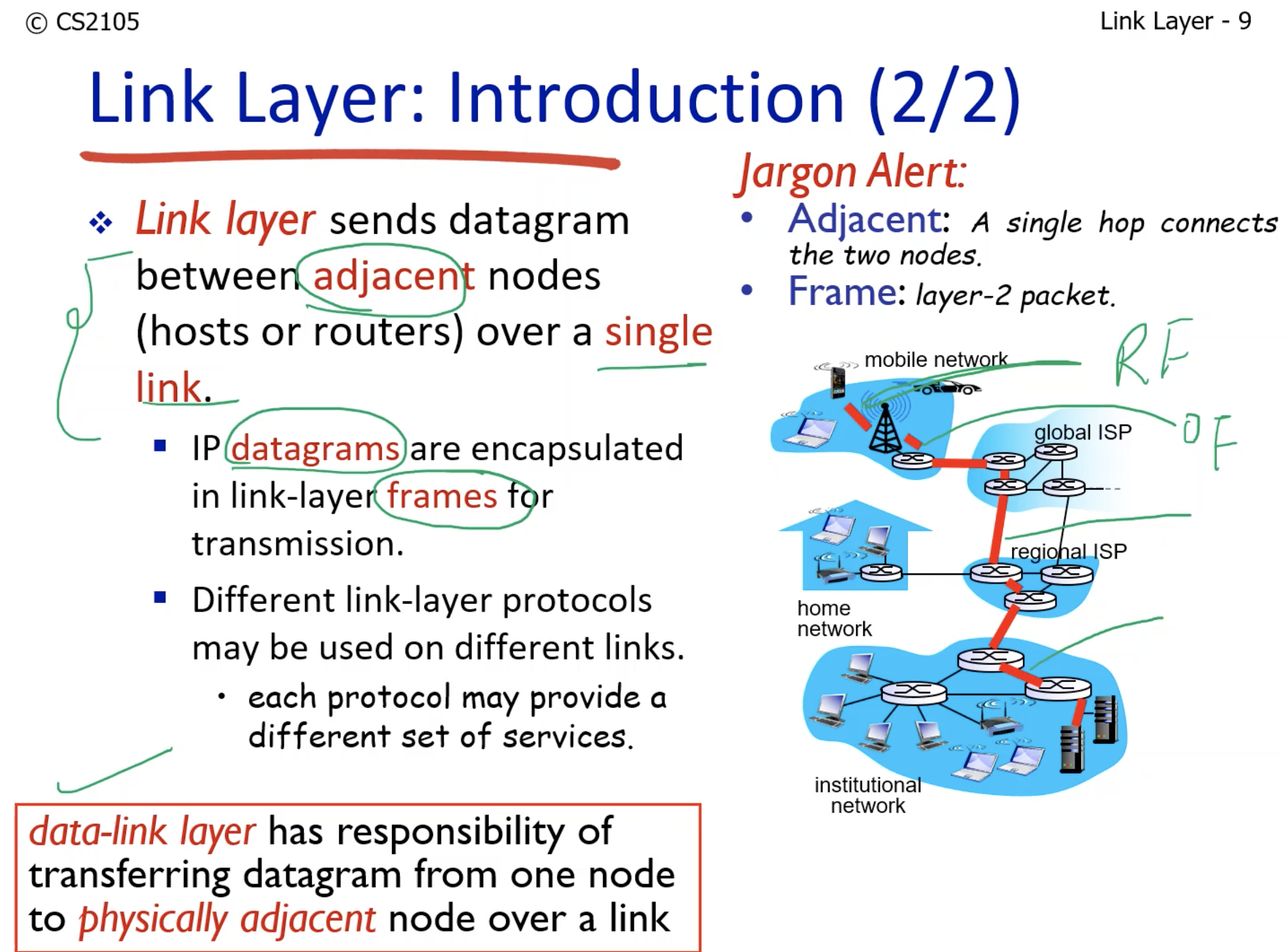
- We are only talking about single links. Each link can have different properties (links could be undersea, wireless, or physical).
- Adjacent nodes mean two nodes connected by a single link.
- Frame is the name for the encapsulated IP datagrams.
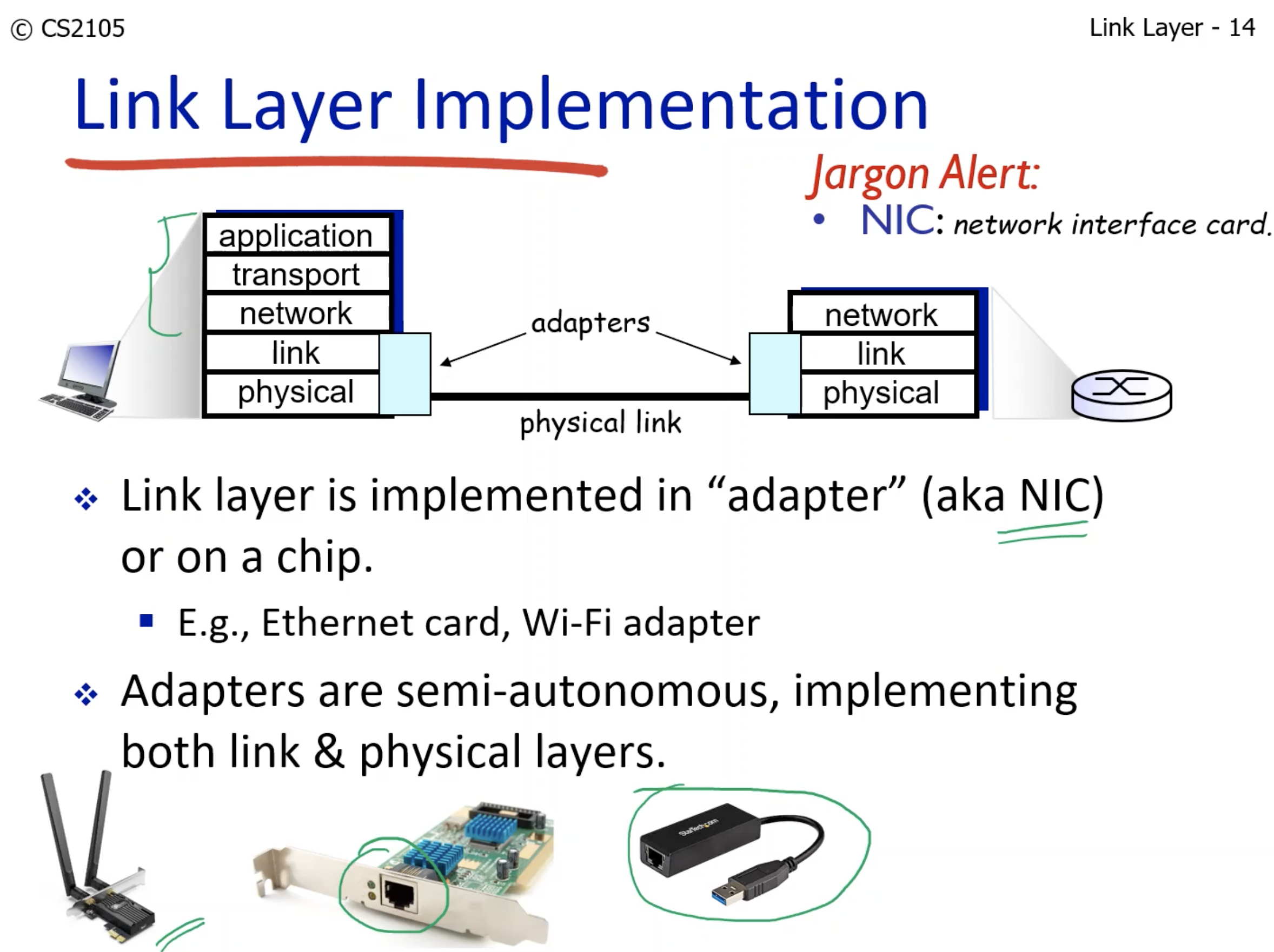
- Why both physical & link layers?
- Link layer: When a NIC implements the Link Layer, it manages tasks such as adding the MAC (Media Access Control) address to data frames, creating and interpreting Ethernet frames, and detecting and possibly correcting errors that occur during data transmission within a local network.
1. Error Detection and Correction
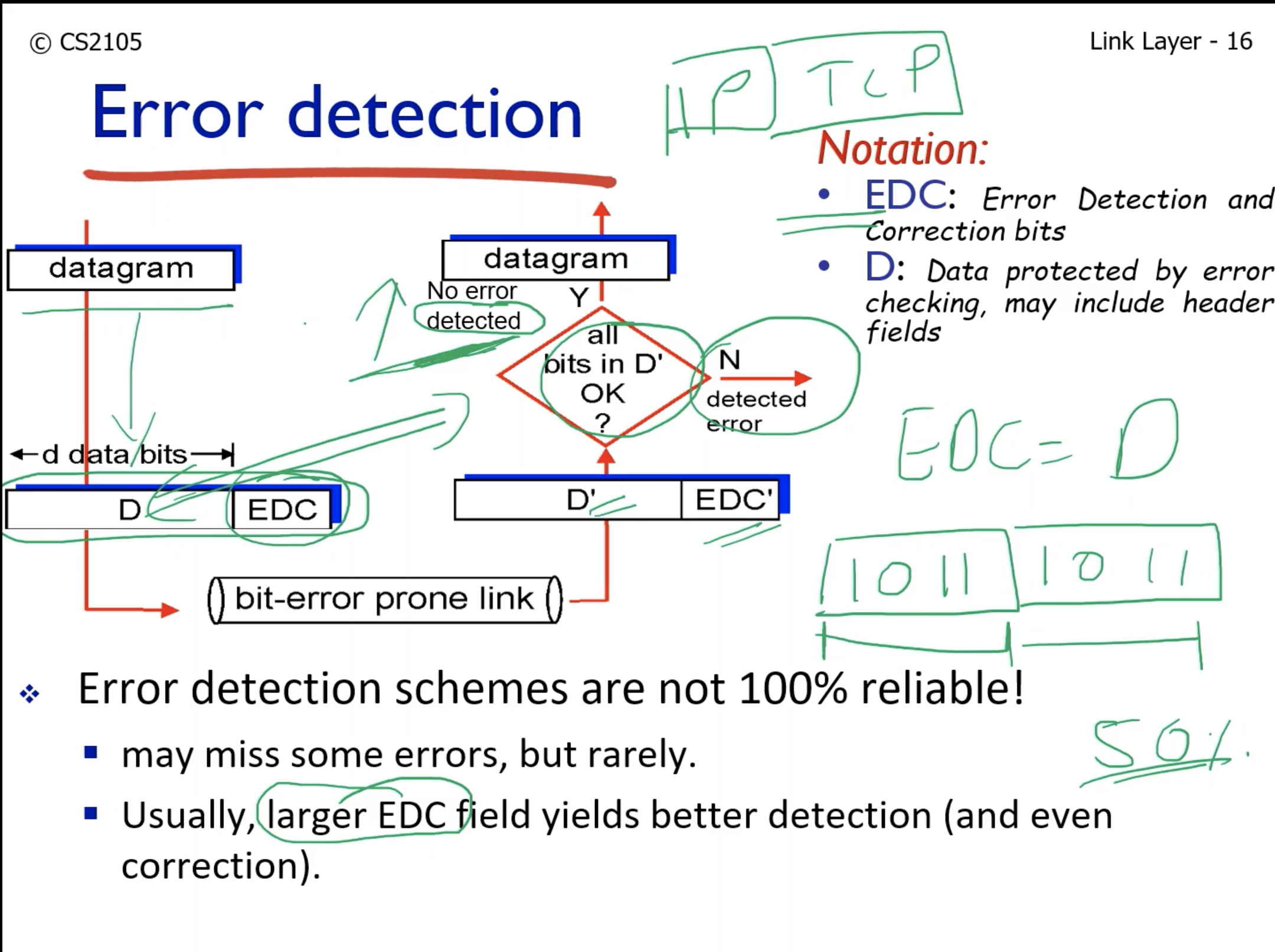
- EDC: Error detection correction bit.
- Are all D' bits ok?
- "No error is detected", may miss some.
- Example of EDC:
- A copy of Datagram: if the EDC is the same as D, there is no error.
- However, this means the throughput is halved, meaning that the bandwidth is halved.
1-1. Parity Check
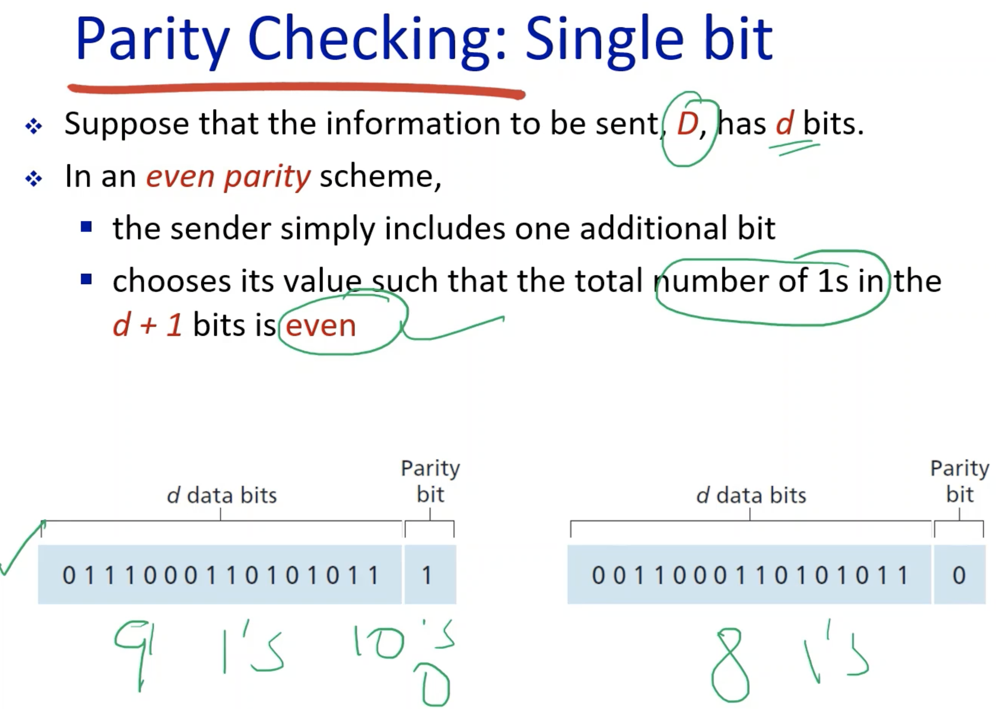
- The parity bit is 1 if adding one makes the # of 1 even.
- Else it is 0.
- Simple, easy to implement.
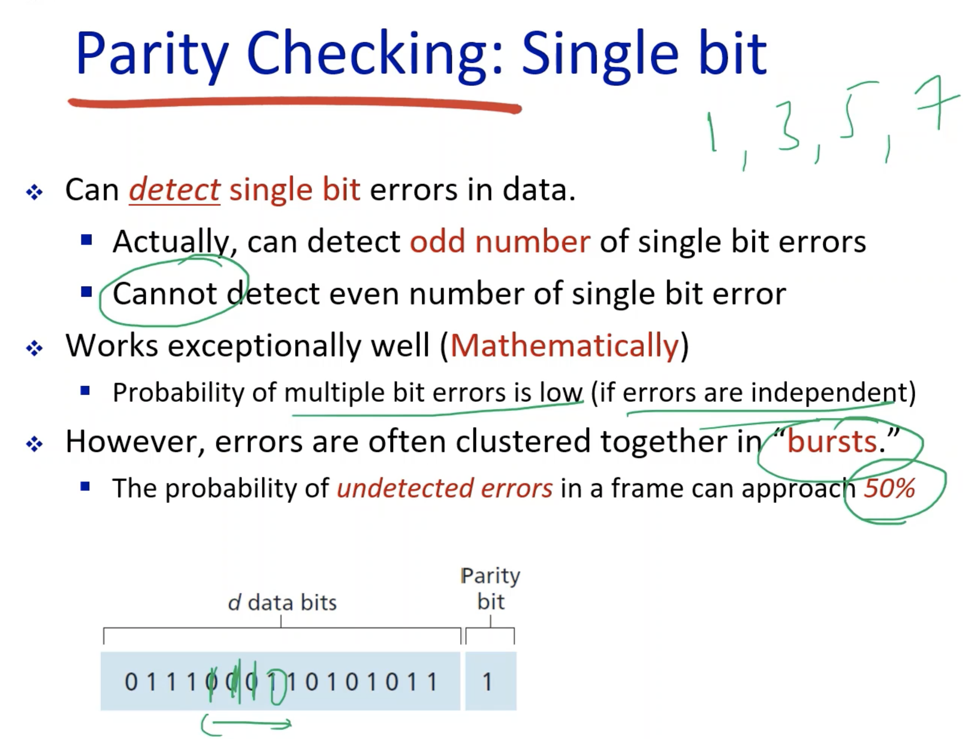
- Good for detecting single bit errors.
- Cannot detect even number of bit errors.
- Works 50% of cases.
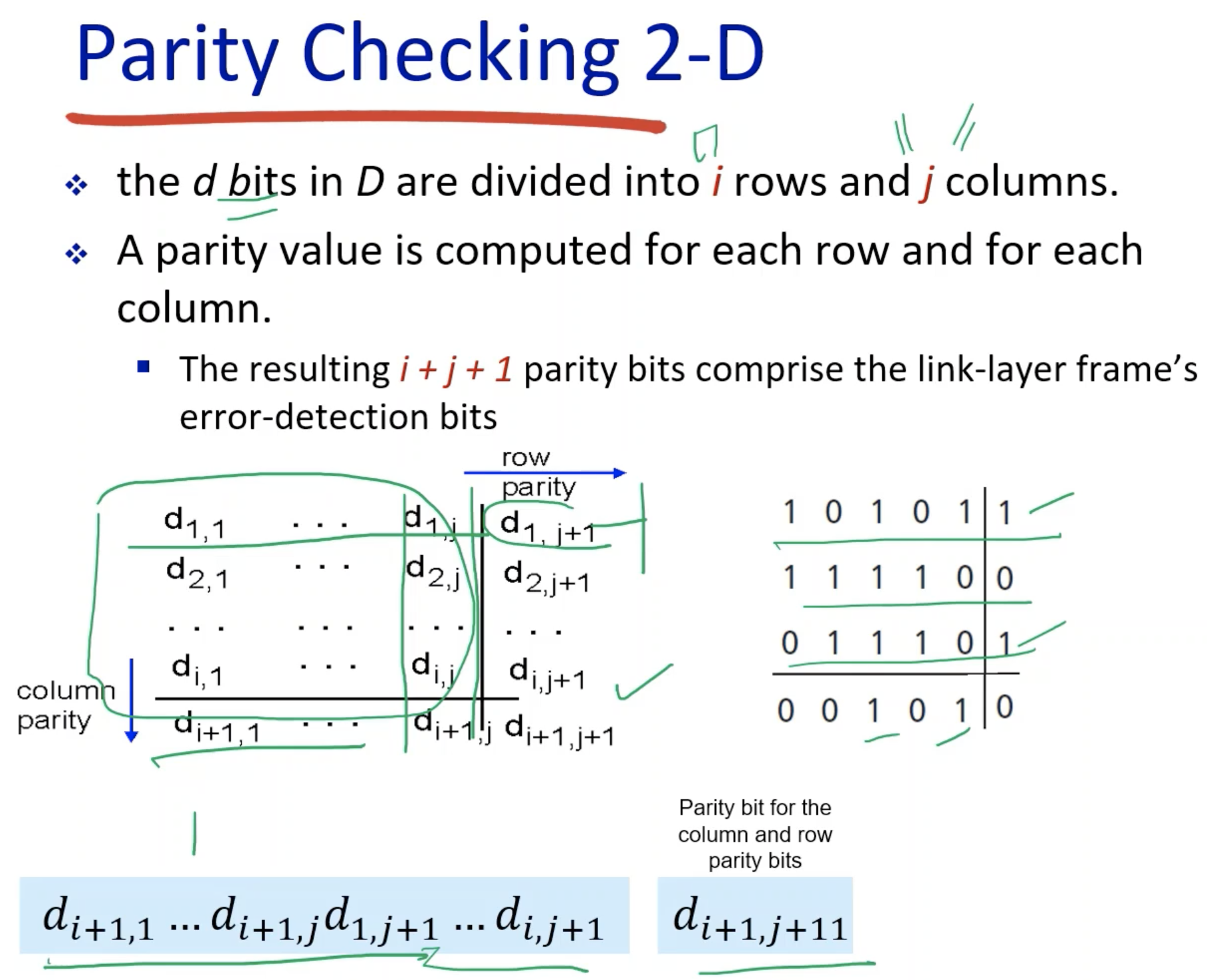
- The corner: the parity bit for the parity bits.
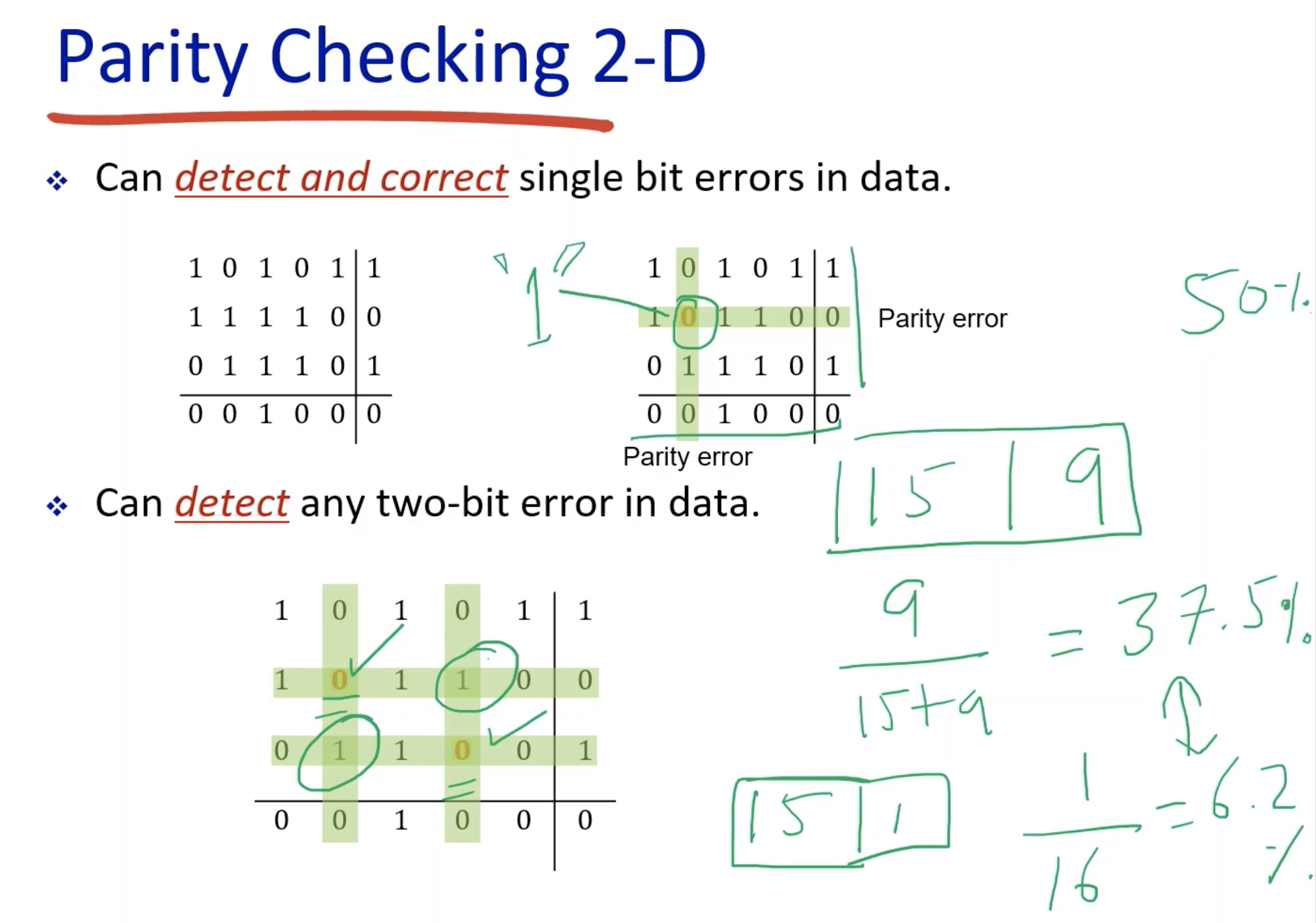
- Can flip the error bit:
- We have achieved the error correction.
- Can reduce the overhead of retransmission if it is required:
- Throughput increases.
- In two-bit error, the receiver has no idea which two of the 4 intersections are erroneous.
- The justification of using the 2-D instead of 1-D must be right:
- The overhead is 9/24 = 37.5% while 1-D is only 1/16 = 6.2%.
- Overhead is calculated EDC/(EDC + D).
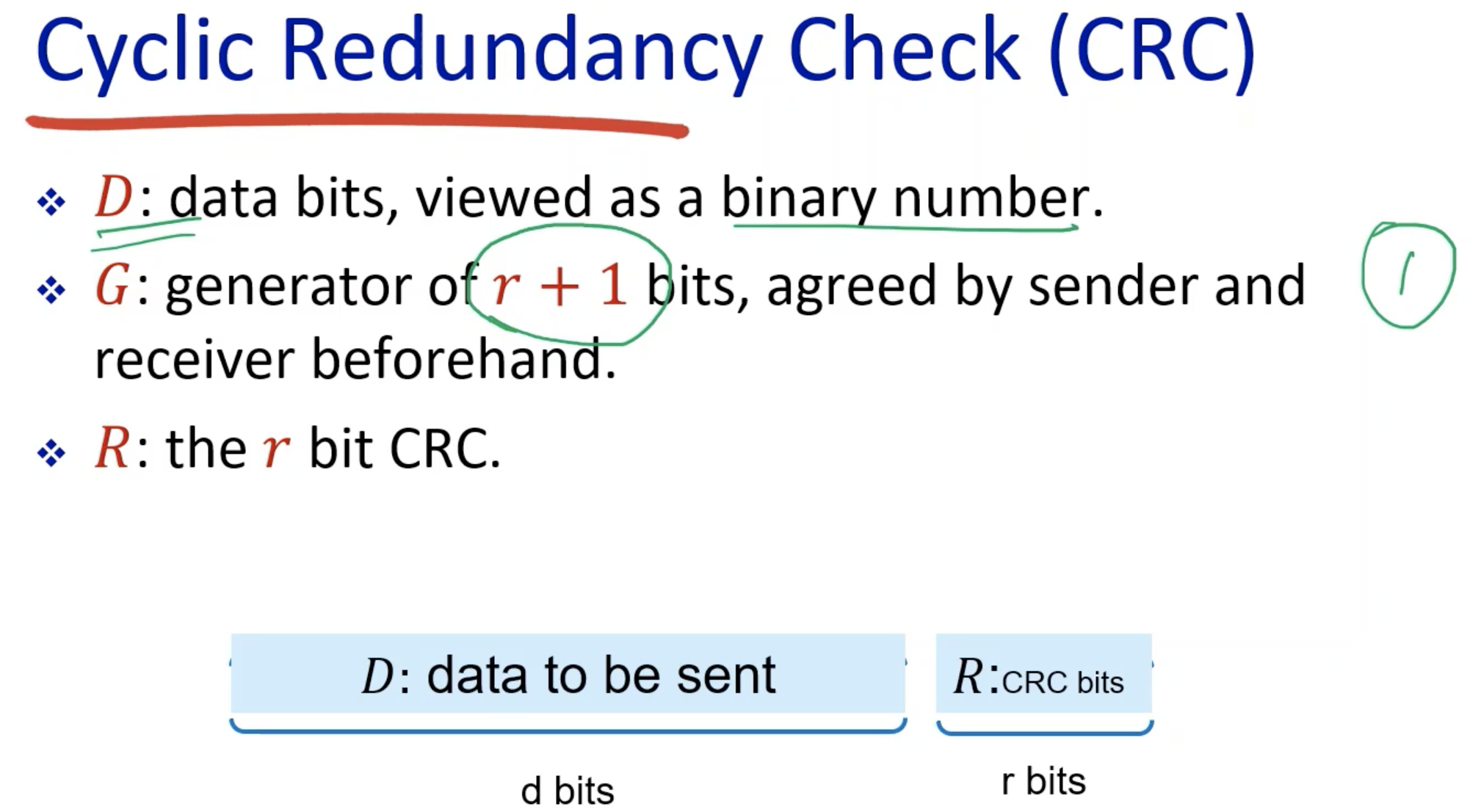
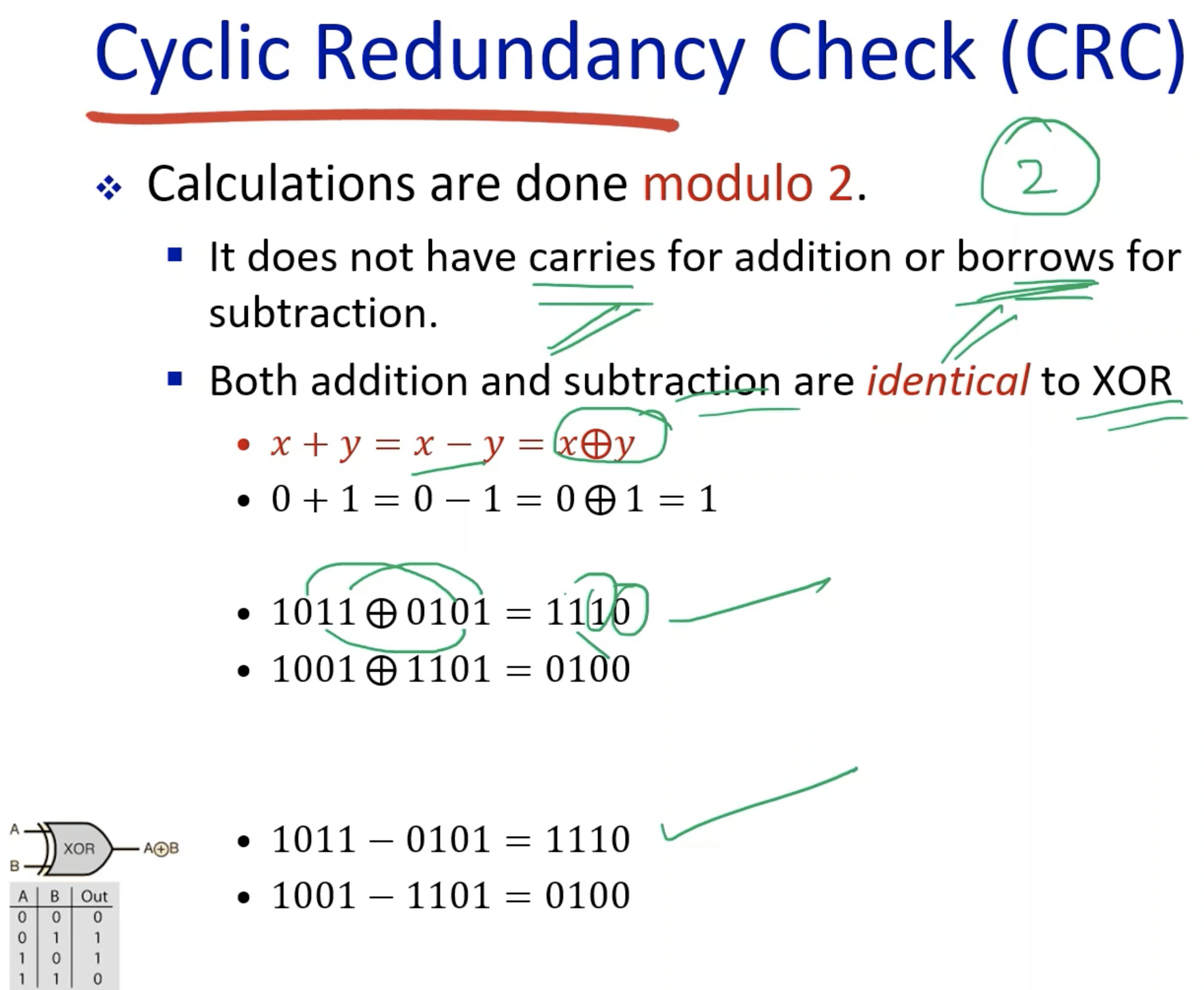
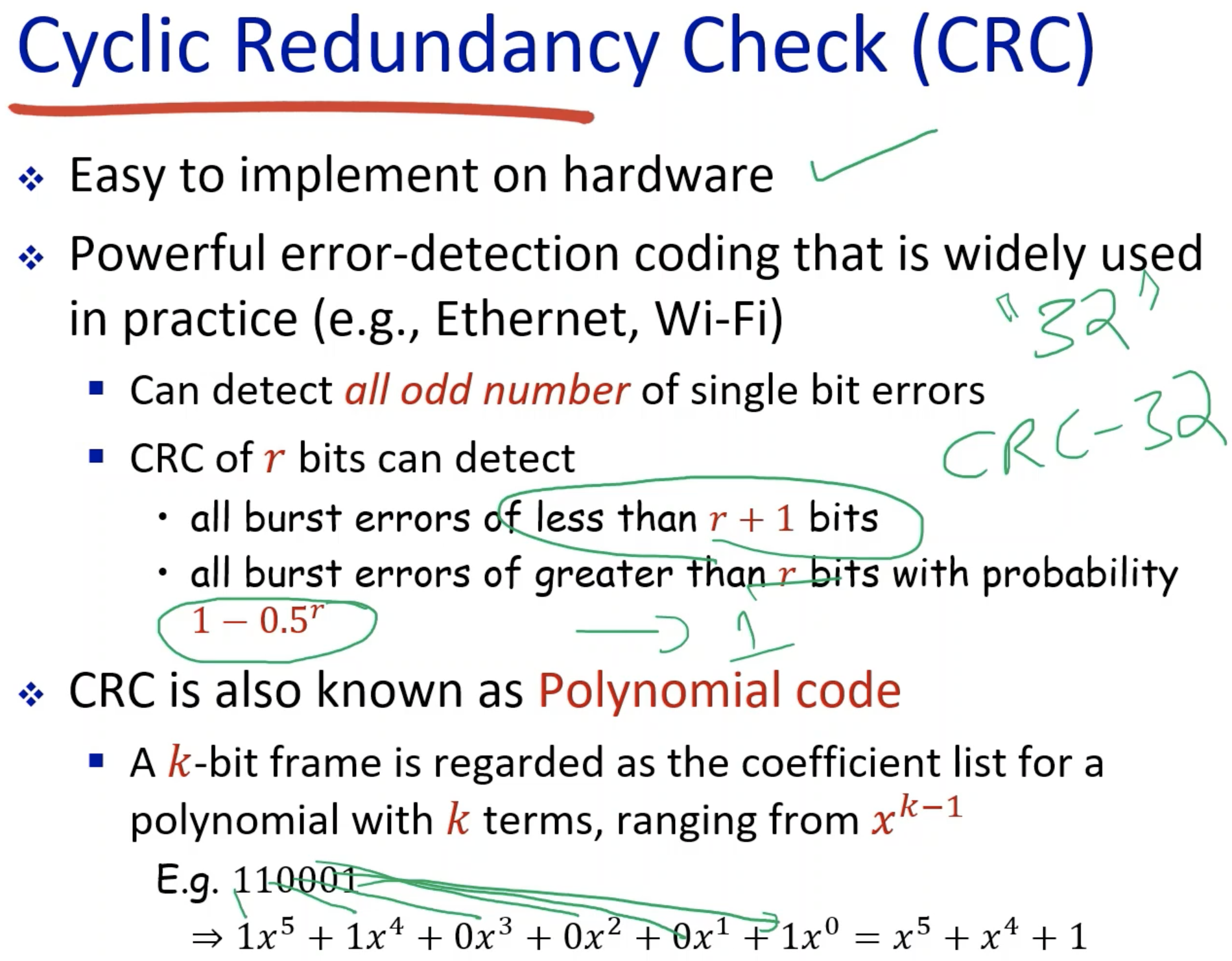
1-2. Cyclic Redundancy Check
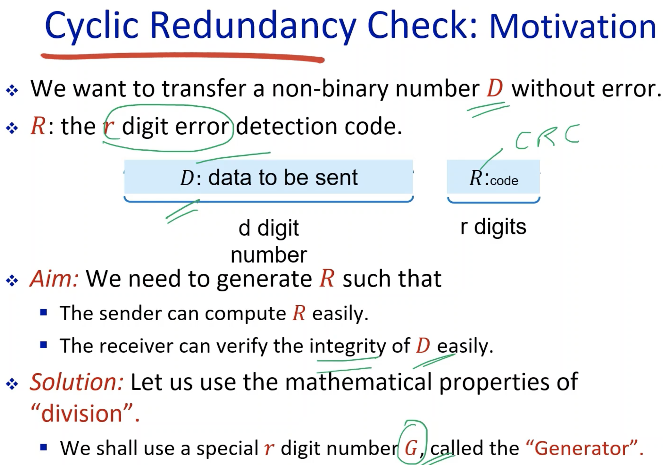
- The generator is known to both sender and the receiver.
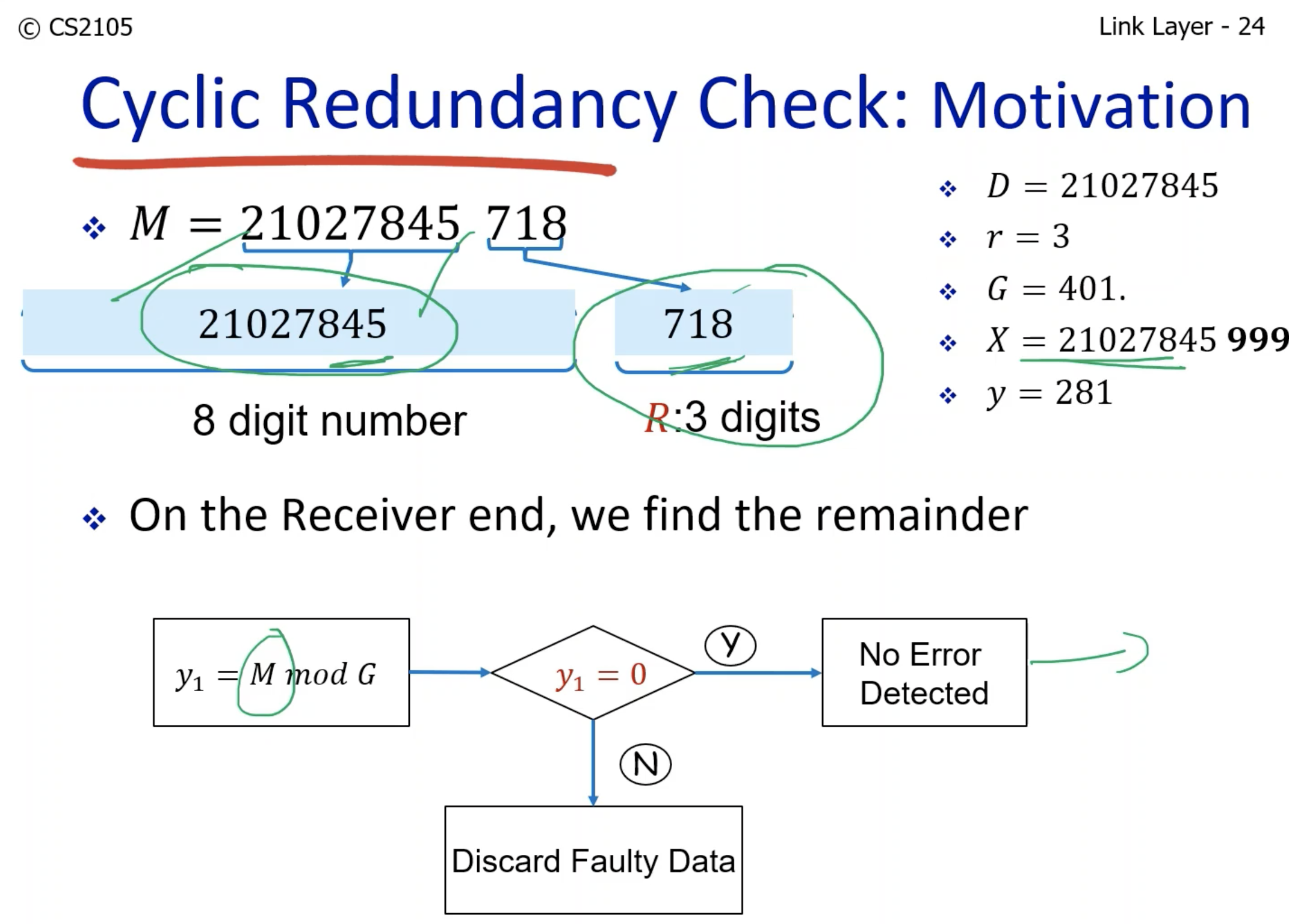
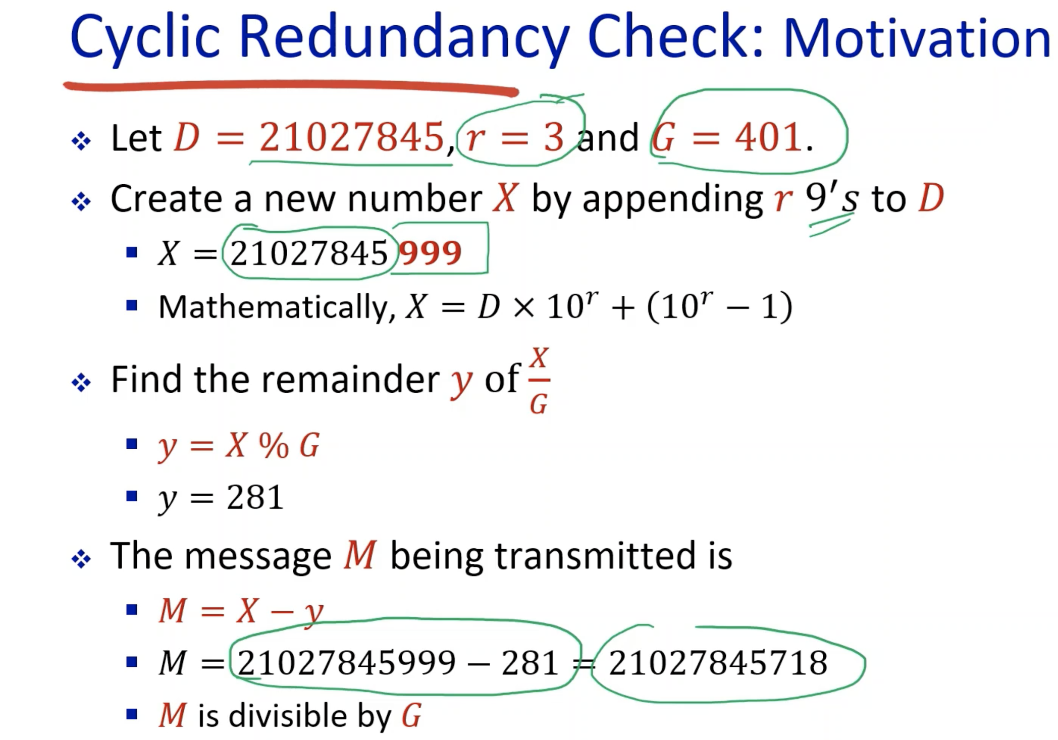
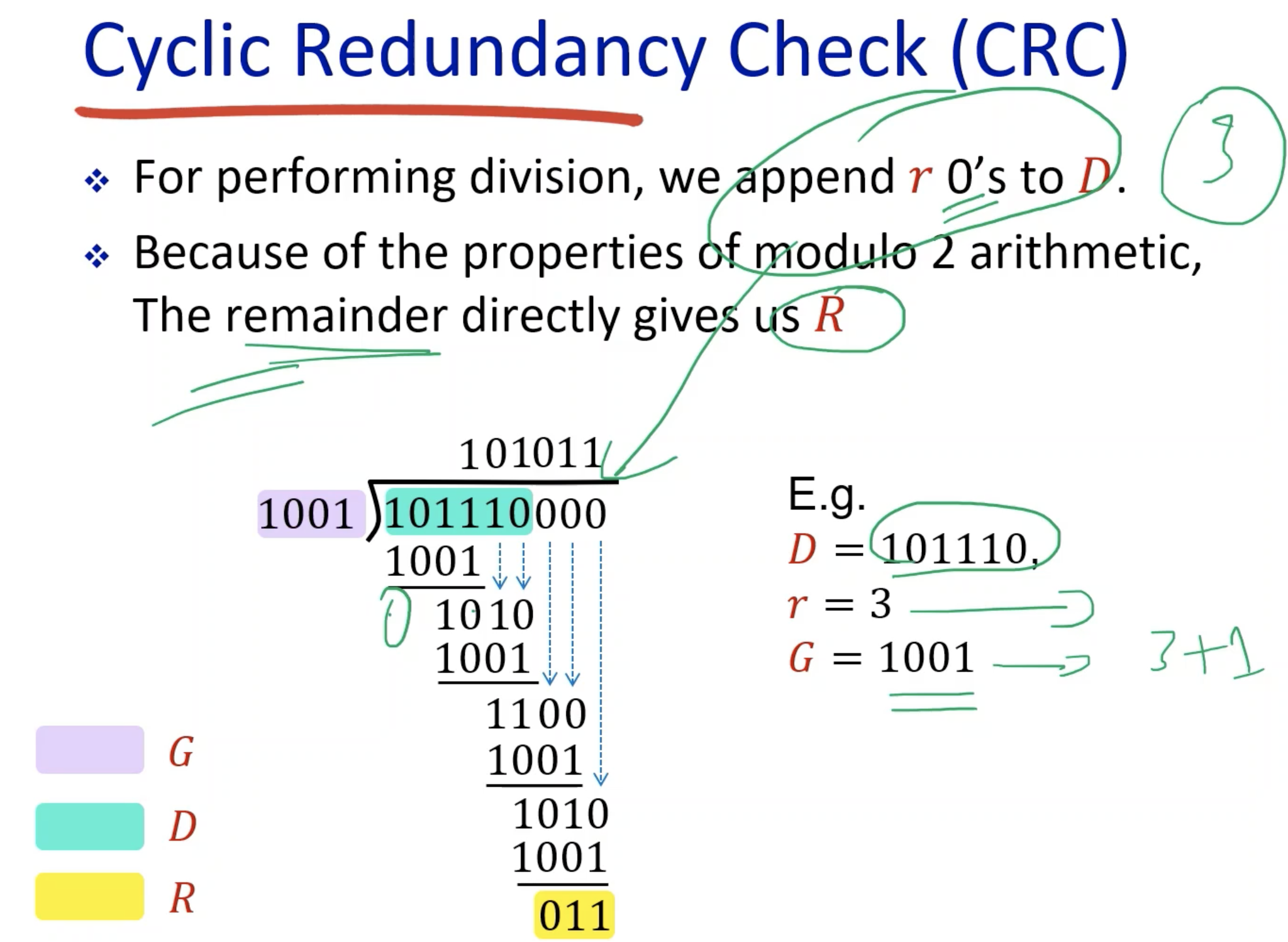
- The purpose of subtracting the remainder was for the receiver to divide the M by the generator, so to check if there is no error the remainder on the receiver side is 0.
- The actual CRC is operated in kind of the same way as the decimal example above.


everything happens for a reason