
🐣1.Gazebo의 Ros 노드
Gazebo에서 여러가지동작을 하는 명령어를 터미널을 이용 할 수 있다.
아래의 코드에 추가로 덧붙혀서 사용할 수 있으며 각각의 기능에 대해서 알아보자.
$rosservice call gazebo/ pause_phsicsgazebo의 모든 객체들이 멈추게 된다.
unpause_phsics일시정지가 해제된다.
reset_simulator모든 오브젝트의 위치를 초기 설정으로 되돌린다.
reset_world모든 오브젝트의 위치를 초기 설정으로 되돌린다.(시뮬레이션 시간 포함)
👀2.Gazebo Tag
urdf 파일에서 gazebo 속성을 추가하여 gazebo 시뮬레이션에 적용될 속성을 추가 할 수 있다.
2.1 Tag로 색상 부여하기
지난 시간에 urdf 파일의 내용을 수정하여 로봇의 구성 및 생상을 변경하였었다. 하지만 Rviz상에서 잘 적용되던 색상같은경우 Gazebo 환경에서 로봇을 소환하였을 때 색이 없는 것을 확인 할 수 있었다.
아래의 사진과 같이gazebo 상에서 색상이 없는 모습
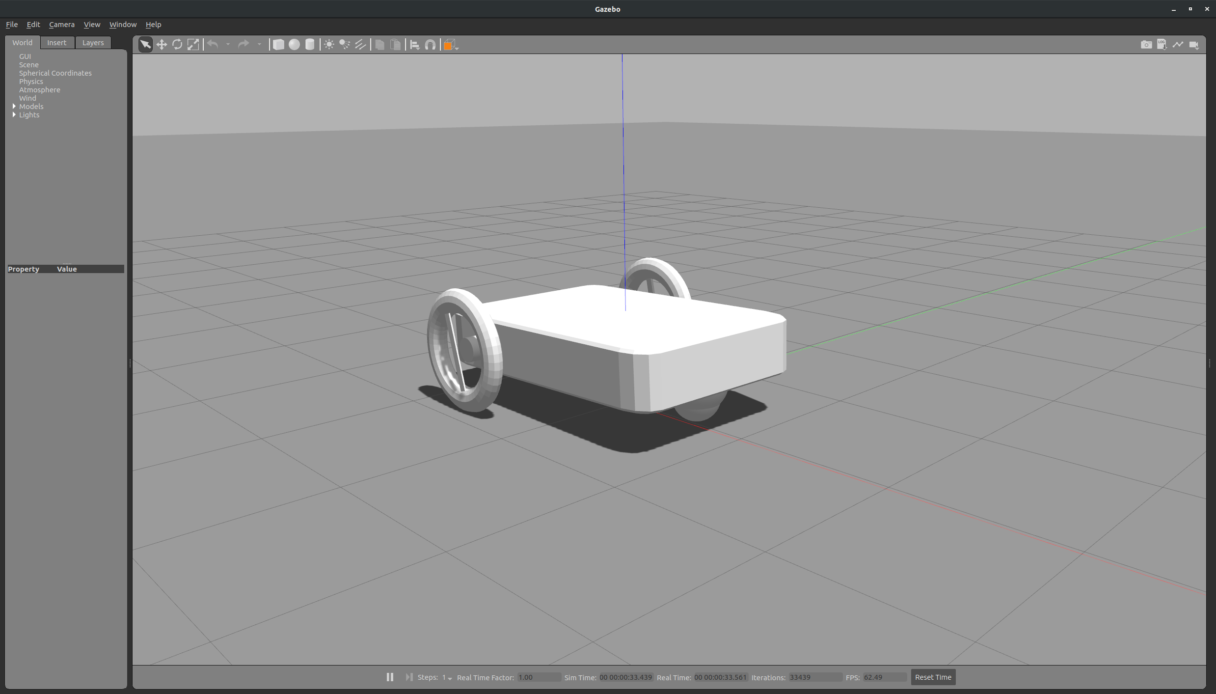
이를 해결하기 위해서는 urdf파일에 gazebo tag를 입력하여 원하는 색상 및 해당 객체의 여러가지 값들을 변경 할 수 있다.
코드를 입력하여 물체의 색상을 넣어보고, 마찰계수를 넣는 코드를 작성해보자.
🤖robot.urdf
...
	<gazebo reference="link_chassis">
		<material> Gazebo/Purple </material>
	</gazebo>
	<gazebo reference="link_caster_wheel">
		<material> Gazebo/Grey </material>
	</gazebo>
	<gazebo reference="link_left_wheel">
		<material> Gazebo/Black </material>
	</gazebo>
	<gazebo reference="link_right_wheel">
		<material> Gazebo/Black </material>
	</gazebo>
...
색상 테그를 추가한 화면
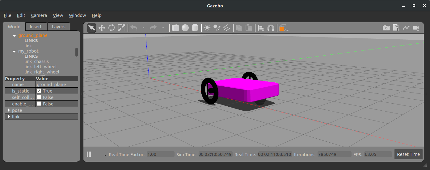
gazebo material 확인
$vim /usr/share/gazebo-9/media/materials/scripts/gazebo.material위 명령어를 통해 위 코드의 색상에 사용된 Gazebo/Black 과 같이 gazebo tag에서 사용할 수 있는 material 을 확인 할 수 있다.
2.2 Tag로 물체 마찰계수 부여하기
추가로 로봇 모델에 tag를 추가하여 마찰 설정을 해보자.
🤖robot.urdf
...
	<gazebo reference="link_chassis">
		<material> Gazebo/Purple </material>
	</gazebo>
	<gazebo reference="link_caster_wheel">
		<material> Gazebo/Grey </material>
		<mu1>0</mu1>
		<mu2>0</mu2>
	</gazebo>
	<gazebo reference="link_left_wheel">
		<material> Gazebo/Black </material>
		<mu1>1</mu1>
		<mu2>1</mu2>
	</gazebo>
	<gazebo reference="link_right_wheel">
		<material> Gazebo/Black </material>
		<mu1>1</mu1>
		<mu2>1</mu2>
	</gazebo>
...
Force를 가하여 움직이는 모습
🔌3. ROS Plugin
플러그인을 사용하면 Gazebo에서 유용한 기능을 추가할 수 있다.
3.1 Robot Differential Driver
3.1.1 코드 작성
🐍move_simple.py
#! /usr/bin/env python
import rospy
from geometry_msgs.msg import Twist
from nav_msgs.msg import Odometry
def odom_callback(msg):
rospy.loginfo('X: %s / Y: %s' % (msg.pose.pose.position.x,msg.pose.pose.position.y))
def main():
odom_sub = rospy.Subscriber('odom',Odometry,odom_callback)
twist_pub = rospy.Publisher('cmd_vel', Twist,queue_size=10)
rospy.init_node('move_simple_node', anonymous=True)
rate = rospy.Rate(10)
while not rospy.is_shutdown():
vel_msg = Twist()
vel_msg.linear.x = 0.3
vel_msg.linear.z = 0.3
twist_pub.publish(vel_msg)
rate.sleep()
if __name__=='__main__':
try:
main()
except rospy.ROSInterruptException:
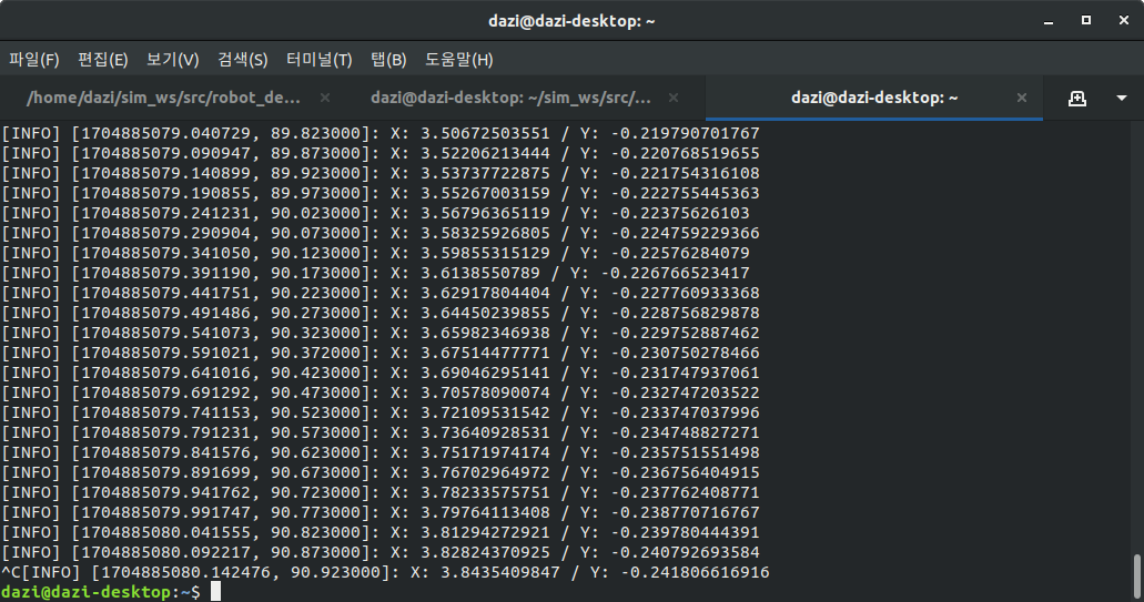
pass3.1.2 실행화면
위 파이썬 코드를 실행시키면 아래와 같이 로봇이 움직이게 된다.
X,Y 좌표정보가 갱신되는 것도 확인 할 수 있다.
3.2 Robot Laser Sensor
3.2.1 코드 작성
🤖robot.urdf
...
<!-- Gazebo tags - Laser scan -->
<gazebo reference="joint_laser_scan_chassis">
<preserveFixedJoint>true</preserveFixedJoint>
</gazebo>
<gazebo reference="link_laser_scan">
<material>Gazebo/DarkGrey</material>
</gazebo>
<!-- Laser scan -->
<joint name="joint_laser_scan_chassis" type="fixed">
<origin rpy="0 0 0" xyz="0.8 0 0.3" />
<child link="link_laser_scan" />
<parent link="link_chassis" />
<joint_properties damping="1.0" friction="1.0" />
</joint>
<link name="link_laser_scan">
<inertial>
<origin xyz="0 0 0" rpy="0 0 0" />
<mass value="0.5" />
<inertia ixx="0.000252666666667" ixy="0" ixz="0" iyy="0.000252666666667" iyz="0" izz="0.0005"/>
</inertial>
<visual>
<origin xyz="0 0 0" rpy="0 0 0" />
<geometry>
<cylinder radius="0.15" length="0.20"/>
</geometry>
<material name="Red">
<color rgba="0.7 0.1 0.1 1" />
</material>
</visual>
<collision>
<origin xyz="0 0 0" rpy="0 0 0"/>
<geometry>
<cylinder radius="0.15" length="0.20"/>
</geometry>
</collision>
</link>
<gazebo reference="link_laser_scan">
<sensor type="ray" name="head_hokuyo_sensor">
<pose>0 0 0 0 0 0</pose>
<visualize>true</visualize>
<update_rate>20</update_rate>
<ray>
<scan>
<horizontal>
<samples>720</samples>
<resolution>1</resolution>
<min_angle>-1.570796</min_angle>
<max_angle>1.570796</max_angle>
</horizontal>
</scan>
<range>
<min>0.20</min>
<max>10.0</max>
<resolution>0.01</resolution>
</range>
<noise>
<type>gaussian</type>
<mean>0.0</mean>
<stddev>0.01</stddev>
</noise>
</ray>
<plugin name="gazebo_ros_head_hokuyo_controller" filename="libgazebo_ros_laser.so">
<topicName>/laser/scan</topicName>
<frameName>sensor_laser</frameName>
</plugin>
</sensor>
</gazebo>
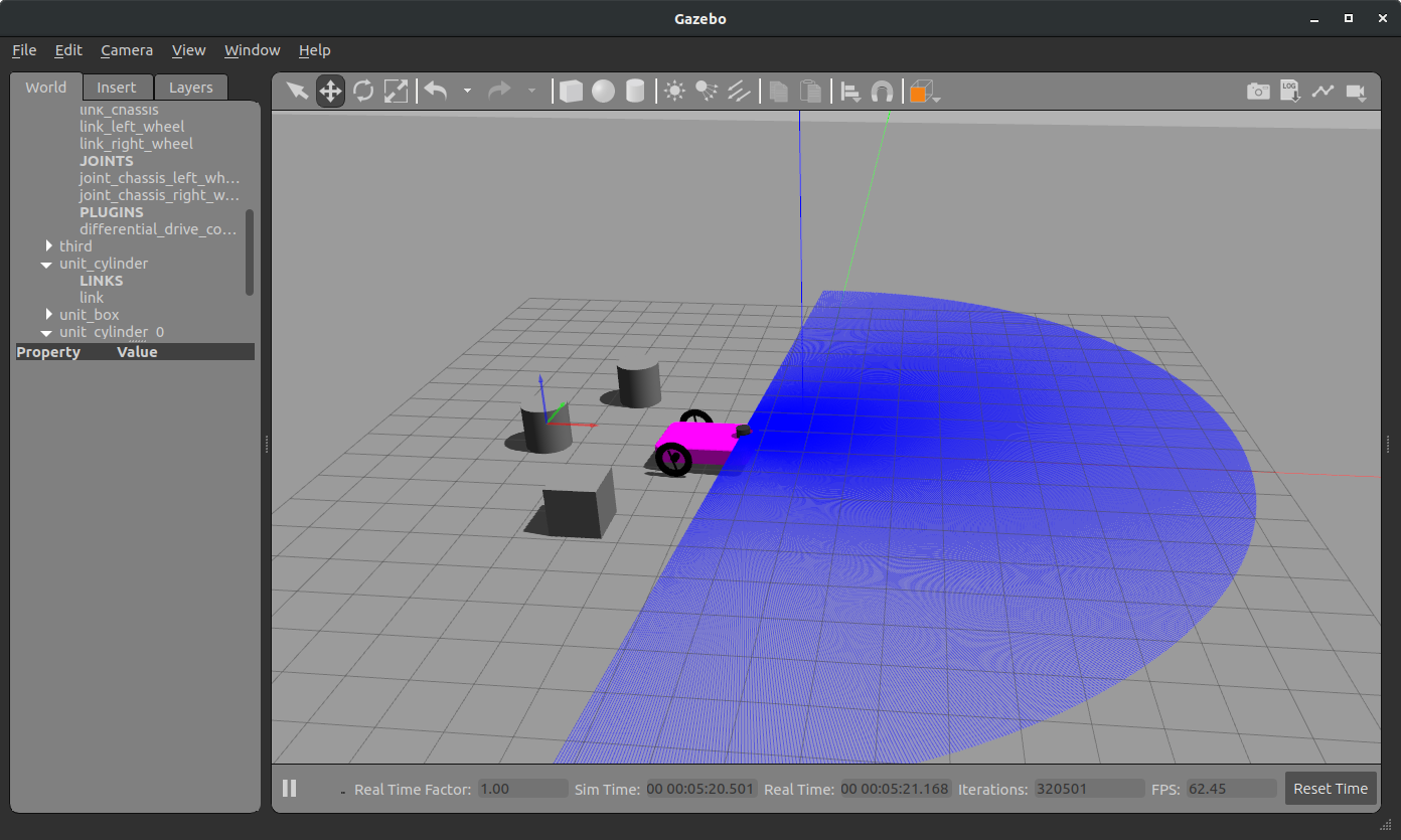
...urdf 파일에 Laser sensor Plugin에 대한 정보를 입력하고 , Ladar 센서 형태를 로봇의 전면에 생성한다. 아래의 사진과 같이 센서의 범위를 눈으로 확인 할 수 있다. visualize 설정을 통해 레이저를 보이지 않게 할 수도 있다.
🐍move_with_laser.py
#!/usr/bin/env python

import rospy
from geometry_msgs.msg import Twist
from sensor_msgs.msg import LaserScan

def laser_callback(msg):
    rospy.loginfo('Minimum distance is: %s' % min(msg.ranges))

def main():
    laser_sub = rospy.Subscriber('laser/scan', LaserScan, callback=laser_callback)
    twist_pub = rospy.Publisher('cmd_vel', Twist, queue_size=10)

    rospy.init_node('move_with_laser_node', anonymous=True)
    rate = rospy.Rate(10) # 10hz

    while not rospy.is_shutdown():
        twist_msg = Twist()
        twist_msg.linear.x = 0.3
        twist_msg.angular.z = 0.3
        twist_pub.publish(twist_msg)
        rate.sleep()

if __name__=='__main__':
    try:
        main()
    except rospy.ROSInterruptException:
        pass
로봇의 동작 및 Laser 센서 값을 통해 최단 거리를 계산하는 코드이다.
3.2.2 실행화면
1.gazebo 실행화면
2.터미널 실행화면
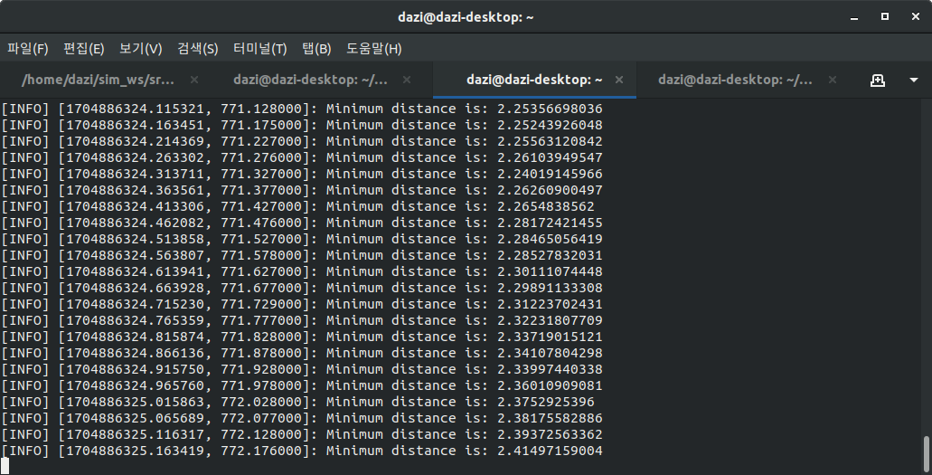
위 사진과 같이 로봇이 회전운동하면서 아래의 터미널과 같이 Ladar에서 가장 가까운 거리를 계산하여 출력되는 것을 확인 할 수 있었다.
3.3 XACRO
로봇 XML 파일을 생성할 때 여러가지 요소의 값을 동시에 바꾸고 싶었던 적이 있는가? 그런 행위를 가능하게 하는 것이 XACRO이다.
XACRO란 XML + Macro의 합성어로 로봇모델을 간단하게 메크로를 사용하여 XML 파일을 생성 할 수 있는 프로그램이다. Parameter를 사용하여 더욱더 빠르고 쉽게 urdf파일을 생성 할 수 있다. 실습을 통해 XACRO 사용법을 알아보자.
3.3.1 코드작성
🤖robot.xacro
...
    <xacro:include filename="$(find robot_description)/urdf/robot.gazebo" />

    <!-- Parameters -->
    <xacro:property name="chassis_mass" value="10" />
    <xacro:property name="pi" value="3.1415926535897931"/>

    <!-- Link - chassis -->
    <link name="link_chassis">
        <inertial>
            <mass value="${chassis_mass}" />
            <origin xyz="0 0 0.3" rpy="0 0 0" />
            <inertia ixx="1.5417" ixy="0" ixz="0" iyy="3.467" iyz="0" izz="4.742" />
        </inertial>

        <collision>
            <!-- <geometry>
                <box size="2 1.3 0.4" />
            </geometry> -->
            <geometry>
                <mesh filename="package://robot_description/meshes/chassis.stl" />
            </geometry>
        </collision>

        <visual>
            <geometry>
                <mesh filename="package://robot_description/meshes/chassis.stl" />
            </geometry>
            <!-- <geometry>
                <box size="2 1.3 0.4" />
            </geometry> -->
            <material name="DarkBlue">
                <color rgba="0.2 0.2 0.4 1" />
            </material>
        </visual>
    </link>
    ...
Parameters 항목에서 변수에 값을 선언하여 사용할 수 있다.
chassis_mass 값을 10으로 선언하였고 chassis_mass 변수를 중간에 사용하는 모습을 확인 할 수 있다.
그리고 pi과 같은 상수도 선언하여 사용하면 편리하다.
3.4 Joint Control
Joint Control은 말그대로 관절의 움직임과 제어를 처리하는데 사용되는 도구이다. 로봇 모델의 관절에 대한 토픽을 통해 명령을 보내거나 프로그래밍을 통해 관절을 제어 할 수 있다.
3.4.1 동작화면
코드는 생략하고 동작화면은 아래와 같다.
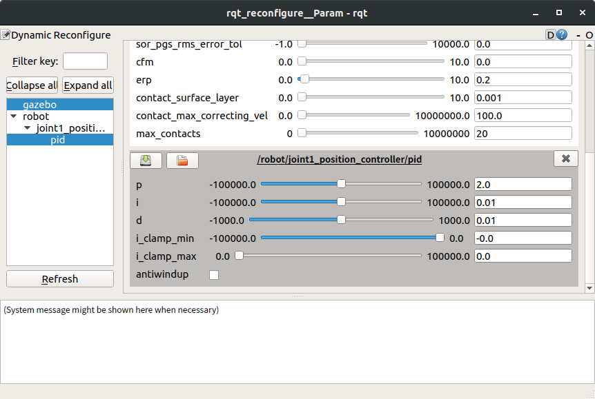
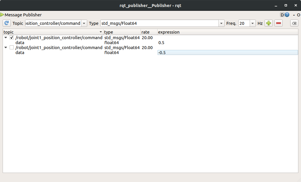
Joint_control_gui 를 통해 아래와 같이 로봇의 꼬리를 제어할 수 있었다.
다음시간에는 Camera Plugin을 설치하여 로봇 시점에서 카메라의 동작을 확인해보겠다.
