1. 3-stage pipeline ARM organization
3-stage pipeline의 구조
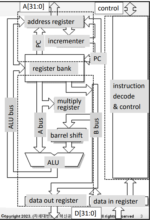
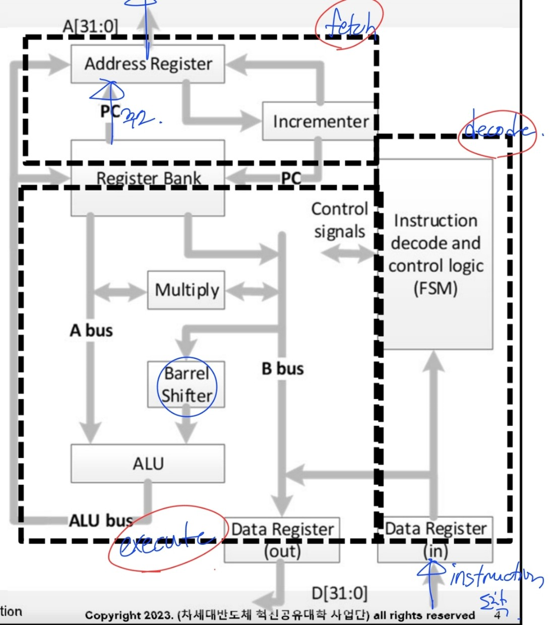
- Register bank
- 2 read ports, 1 write port + 1 read, 1 write port reserved for r15(pc)
- r0 - r14는 mu0 프로세서의 ACC와 비슷
- ADD r2, r1, r0 → r2 : 1 write port / r1,r0 : 2 read port
- r15에는 명령어를 읽어오는 port와 명령어를 보내는 port가 존재
- Barrel shifter
- 2nd operand를 shift or rotate (별도의 cycle 없이 수행됨)
- ALU
- arithmetic과 logic 연산 수행
- Memory address register + incrementer
- ARM은 주소를 내보낼 때 r15와 address register를 거쳐서 내보냄(mu0는 PC에서 바로 주소 나감)
- branch 명령을 제외하고 일반적인 명령을 수행할 때 ALU가 아니라 incrementer에서 명령어 주소 증가 시킨 후 register bank에 저장
- Memory data registers
- data out register : 메모리에 넣을 데이터가 거치는 곳
- data in register : 메모리에서 읽어온 데이터가 거치는 곳 (+ 명령어) (mu0에서 IR같은 역할)
- mu0 : data가 ALU를 거쳐 바로 ACC로 들어감
- Instruction decoder and associated control logic
- data in register에 저장된 명령어는 이 decoder로 전달되어서 해독됨
- data in register에 저장된 data는 B bus를 통해 ALU를 거쳐 register bank에 저장됨
- muliply register
- ALU에선 덧셈, 뺄셈 등의 연산만 수행하고, 곱셈은 따로 곱셈기에서 연산이 수행됨(ARM 한정)
3-stage pipeline의 단계
Fetch
- memory로 부터 명령어 fetch
- 읽어온 명령어는 instruction pipeline에 놓임
Decode
- 명령어가 decode logic에 있음 → datapath의 제어신호 만들어 (다음 execute cycle에서 이용됨)
- 명령어는 datapath에는 존재 X
Execute
- 명령어가 datapath에 있음
- register bank의 data가 읽어짐
- 2nd operand에 한하여 shifted
- ALU에서 결과가 계산되고 그 값이 다시 destination register에 written
★ 3 pipelines는 독립적으로 수행됨!!!!
(stage 별로 구성요소가 겹치지 않음)
⇒ 한번에 3개의 명령어가 처리됨
ARM single-cycle instruction pipeline
- 명령어가 들어가면 3 cycle 뒤에 execute ⇒ 3 cycle latency
- 3 cycle latency가 끝나면 1 cycle마다 결과가 나옴 ⇒ 1 cycle throughput
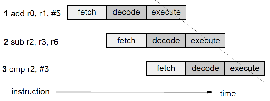
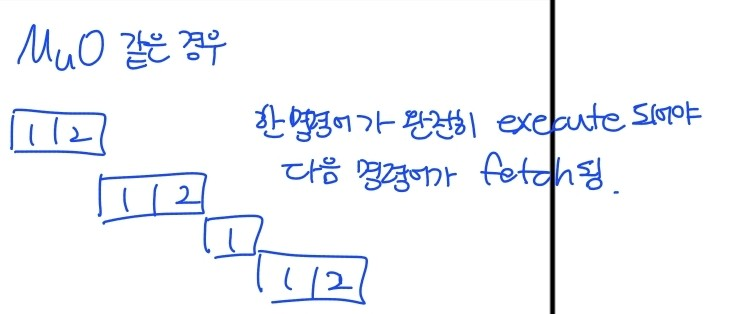
- mu0 프로세서 같은 경우 한 명령어가 완전히 execute되어야 다음 명령어가 fetch
ARM multi-cycle instruction pipeline
- 1: Decode logic : 다음 execute cycle에서 사용할 datapath를 위한 제어신호를 생성
- 2: Multi-cycle execution : 실행 사이클이 2개 이상인 경우(CISC적인 특성) 이 실행 사이클에 의해 지배되어 다음 명령어를 decode 못 함.
- 3: data transfer : 메모리에 접근하는 실행 사이클이 실행되는 cycle에선 명령어 fetch 불가
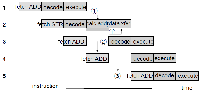
- STR : 실행 2단계(CISC적인 특성)
- calc addr : 데이터를 저장하기 위해 주소값 계산하는 단계
- data xfer : 데이터를 메모리로 보내는 단계- data xfer cycle를 실행하기 위해 이전 decode cycle의 제어 신호 이용 ⇒ decode unit이 이 실행 단계에 의해 지배되어 다음 명령어 decode 불가
- data xfer에서 메모리에 접근하고 있어 해당 사이클에서 다른 명령어를 fetch하지 못 함
- 이런 이유로 thoughput이 완벽하게 1 cycle이 안됨.
- RISC의 경우 throughput을 항상 1 cycle로 유지 (branch 제외)
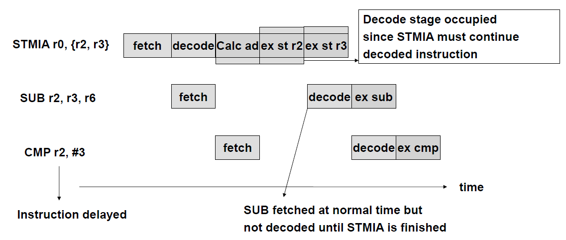
ARM multi-cycle STMIA (store multiple) instruction pipeline
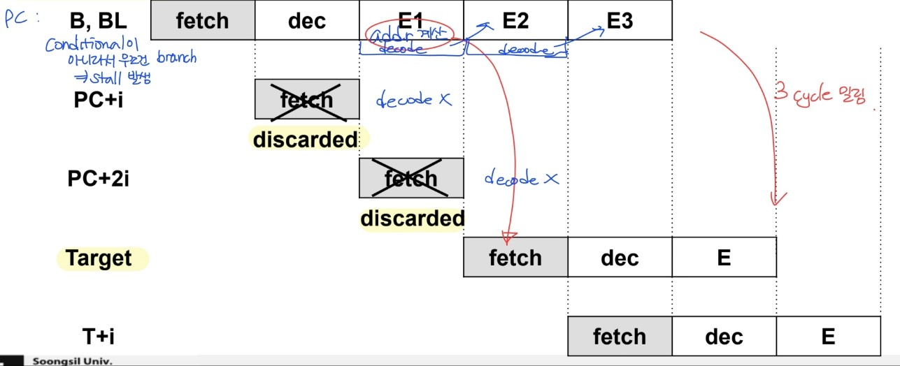
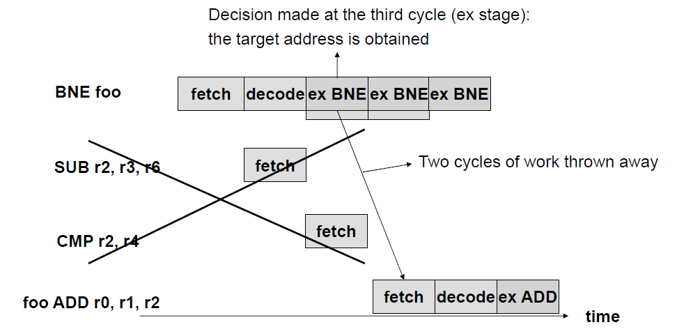
Control stalls : due to branches
- branch penalty : branch → stalls
- branch의 발생 여부에 따라 stall time 결정 - 실행되고 있는 명령어를 다 없애야할 수도 있어
- condition이 계산될 때까지는 어떤 명령어를 fetch해야할 지 알 수 없음
- B, BL : 조건부가 아니라서 무조건 branch → stall 발생
- 첫번째 실행 사이클에서 addr 계산
- addr 계산 이후에 다음 명령어 fetch
- 그 전까지 fetch된 명령어들은 버려져(3 cycle 밀림)
- branch 명령어는 실행사이클이 3 cycle → 두 사이클동안 decode logic 사용 X
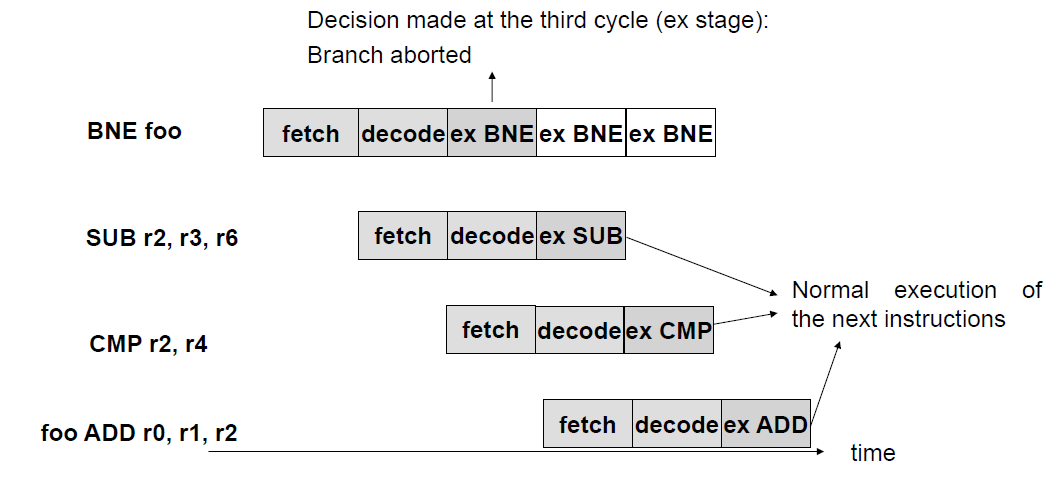
ARM pipelined branch
conditional branch
condition : true → branch
- 이 경우 위와 동일
condition : false → branch X
- 첫번째 실행사이클에서 branch 여부 결정됨
condition에 맞지 않으면 branch aborted - branch 안 하니까 다음 실행 cycle X → decode 점유 현상 X
- branch 명령 실행 했지만 아무 output X
- 다른 명령어들은 정상적으로 동작 → throughput 1 cycle
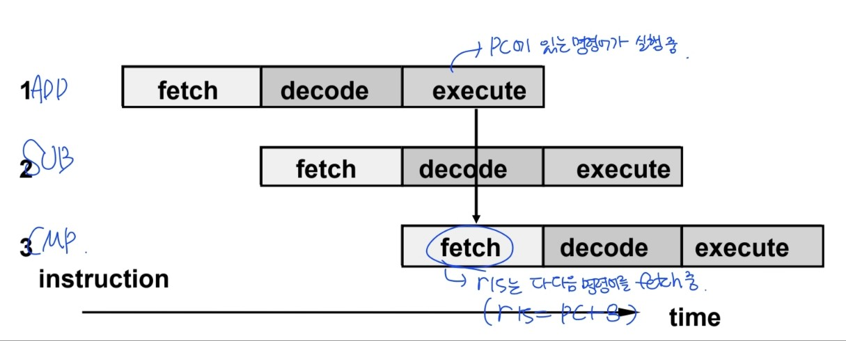
3-stage pipeline의 PC behavior
- 현재 실행되는 명령어보다 PC값이 앞서 나감 ⇒ r15 = PC + 8
- operands는 execution stage에서 읽어짐
★ r15에 들어있는 값 = PC(현재 실행되고 있는 메모리 주소) + 8
Pipeline : how it works
- 모든 명령어들은 한개 이상의 실행 사이클을 갖고 있음
- 1 : 실행 사이클 전에는 decode cycle이 반드시 실행되어야 함
- 2: 1번째 명령어가 실행 cycle에 있을 때, 다다음 명령어가 fetch 되고 있음
- branch 명령 : pipeline을 비우고 다시 채우는 역할 → 2 cycle 기다려야해
2. 5-stage pipeline ARM organization
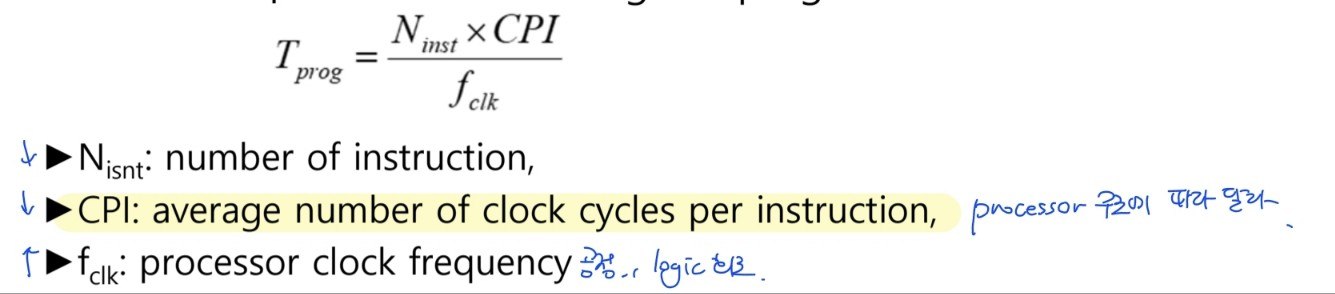
- way to increase performance
- clock 주파수 증가 → 5-stage pipeline 사용- CPI 감소(CPI : 명령어 당 평균 cycle 수)
⇒ ARM9의 forwarding path → 실행 cycle 수를 감소시키는 방향으로 프로세서 재구현
- CPI 감소(CPI : 명령어 당 평균 cycle 수)
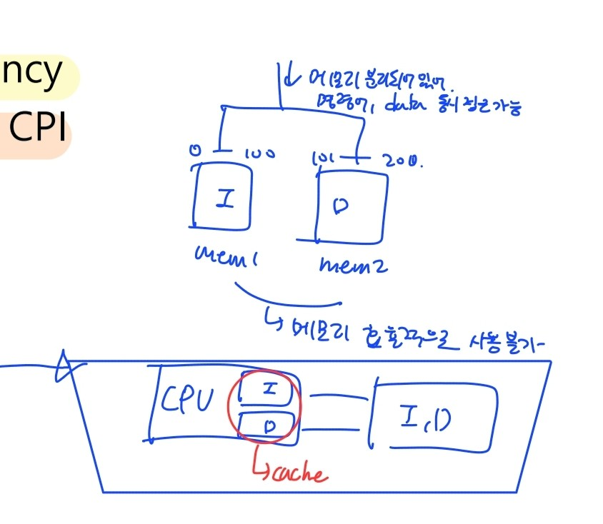
Memory bottleneck
- von-Neumann bottleneck
- 명령어와 data를 하나의 메모리에 저장 → 명령어 읽어오고, data 읽고 쓰는 것을 순차적으로 계속(명령어와 data 동시 접근 불가능(ARM7)) - 3-stage ARM 같은 경우 거의 매 cycle마다 memory에 접근 → 성능 저하
- 5-stage pipeline
- 1 cycle에서 수행해야하는 최대 작업량을 줄임 → high clock frequency 가능
- 명령어와 데이터의 메모리를 분리 → 명령어와 data 동시에 읽어오기 가능 → CPI 감소 - 메모리를 분리시키면 명령어와 data를 동시에 접근 가능하지만 메모리를 효율적으로 사용 불가 → cache 이용
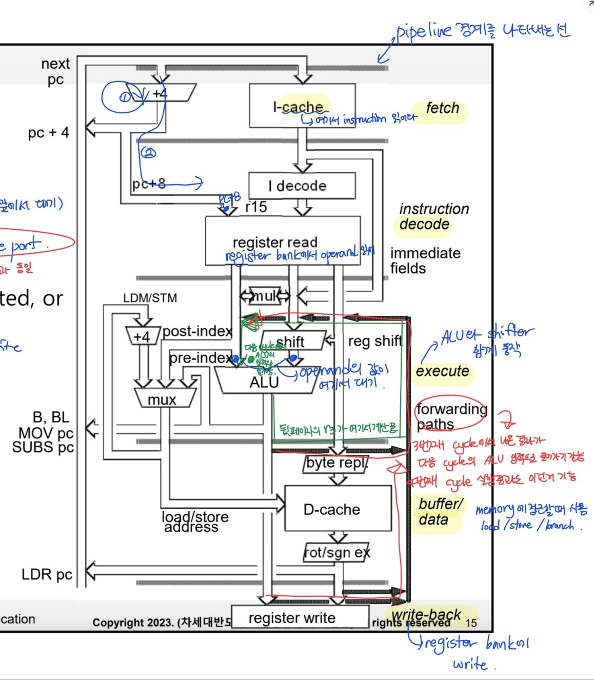
5-stage pipeline(ARM9)
- I-cache & D-cache ⇒ ARM7과의 차이점
- Pipeline stages
1.Fetch
- I cache에서 명령어 읽어옴
- PC + 4가 address register에 저장됨
2.Decode
- 명령어 decode
- register operands read ⇒ ARM7에서 execute 단계에서 했던 것
- 3 read ports & 2 write ports ⇒ ARM7과 동일
- 읽어온 operand 값이 ALU 앞에서 대기 → 다음 cycle에서 ALU의 입력으로 들어옴
- PC + 8 값이 계산됨 (register file 앞에서 대기)
3.Execute
- operand shifted & ALU result generated
- Address is computed(Branch 명령의 경우)
4.Buffer/data
- data memory에 접근(load, store)
- D-cache에서 read/write
- store 명령은 여기서 실행 완료
5.Write-back
- write to register file
- load 명령은 여기서 실행 완료 - execute, buffer/data, write-back ⇒ ARM7에선 execute 단계 하나로 실행
- 메모리 접근이나 branch 관련 명령어들이 사용하는 stage ⇒ Buffer/data, Write-back
Data forwarding
-
명령어 실행 사이클 : 1 cycle → 3 cycle
⇒ 이전 명령어의 destination register가 다음 명령어의 입력으로 쓰이는 경우 2 cycle stall 발생ADD r3,r2,r1, LSL #3 ADD r5, r5, r3, LSL r2 -
r3 계산은 ex1에서 이뤄짐
-
BUT write-back cycle에서 r3에 값이 저장됨(forwarding path가 없는 경우)
-
그 다음 사이클에서 다음 명령어의 첫번째 실행 사이클이 시작될 수 있음
⇒ 이걸 해결하기 위해 data forwarding path가 만들어짐
(forwarding path를 이용하면 다음 cycle에 ex1 실행 가능)
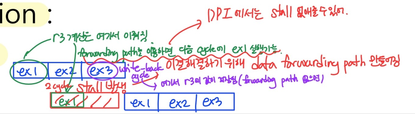
-
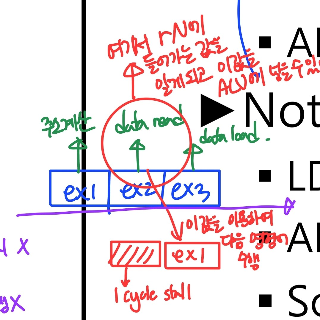
(Data) forwarding paths
- stalling 막기 위해 만들어짐
- DPI에서는 no stall- LDR 명령의 경우 1 cycle stall 발생
	LDR rN,...
ADD r2,r1,rN- rN값은 buffer/data stage에서 값 사용 가능 → 1 cycle stall 발생
- LDR과 ADD 사이에 rN값이 필요하지 않은 명령어를 넣어주면 stalling 문제 해결 가능
ARM9TDMI PC generation(5-stage pipeline)
- 3 stage pipeline
- operand를 execution stage에서 읽어옴 ⇒ r15 = PC + 8 - 5 stage pipeline
- operand를 decode stage에서 읽어옴 ⇒ r15 = PC + 4
⇒ 3 stage 와 5 stage의 호환성 문제 발생 - 5 stage pipeline 동작을 3 stage pipeline 동작과 유사하게 만들어야함.
⇒ I.A.next = I.A.(PC + 4) + 4
address register에는 PC + 4가 들어감 → PC + 4 fetch
⇒ r15 = PC + 8 (decode 단계)
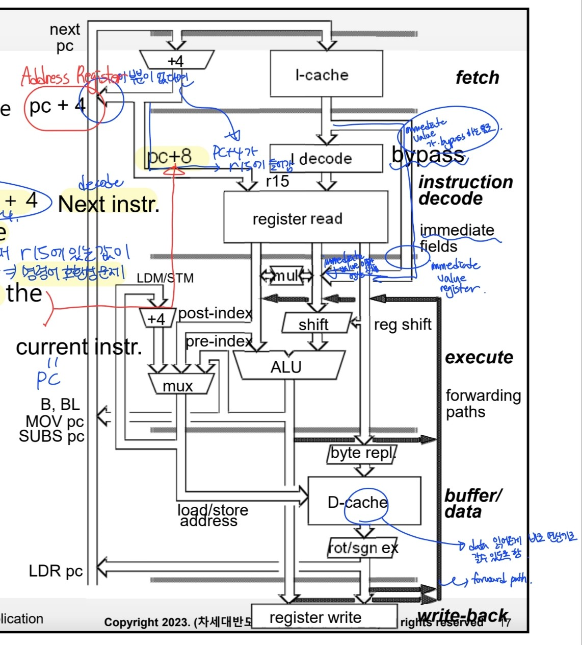
- immediate value는 bypass통로를 통하여 ALU로 전달됨
3. ARM Instruction execution(5-stage pipeline)
DPI (data processing instruction)
- 모든 명령어가 single execution cycle
- r15 = pc + 8
- AR = AR + 4
- immediate value(8bit)는 immediate value register와 shifter를 거쳐 ALU로 감
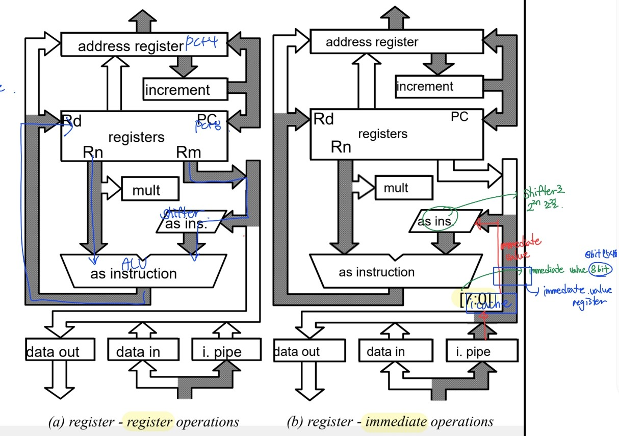
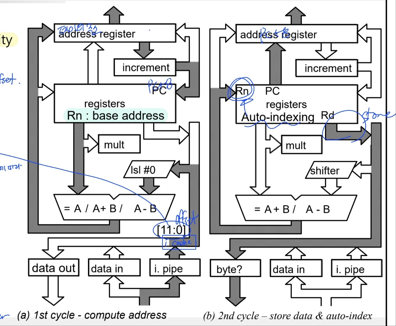
DTI (data transfer instruction)
STR (2 execution cycle)
- compute address
- AR = Rn(base address) op Disp(offset 12bit)
- r15 = pc + 8
- Store data
- mem[AR] = Rd<x:y> (메모리에 data store)
- AR = r15 (다음 명령어 fetch)
- auto-indexing → Rn = Rn +/- 4 (base address 바꿔)
LDR (3 execution cycle)
- Compute address
- AR = Rn(base address) op Disp(offset 12bit)
- r15 = pc + 8
- Read data
- data in buffer = mem[AR]
- AR = r15 (다음 명령어 fetch)
- auto-indexing → Rn = Rn +/- 4 (base address 바꿔)
- register에 data 써
- Rd = data in buffer
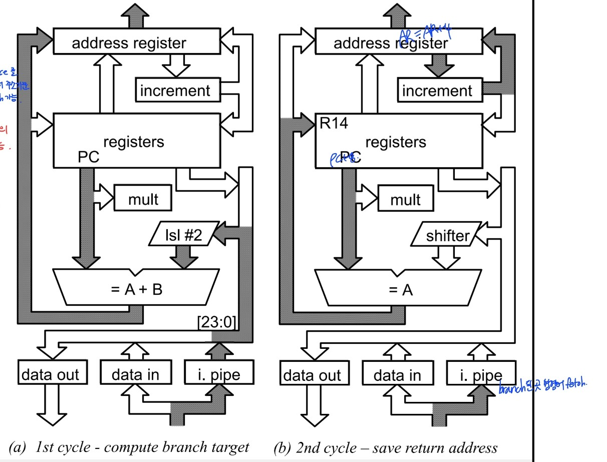
Branch instruction(3 execution cycle)
- target 주소 계산
- AR = r15 + Disp(명령에 포함된 immediate value),lsl #2(word)
- immediate 24bit + 2 bit
- 32bit address space를 가지고 있지만 현재 명령어 주소 기준 +- 25 bit 범위까지 branch 가능
- return addr save (BL 명령어의 경우)
- r14 = r15(PC + 8) (save return addr)
- AR = AR + 4 (branch한 명령어 fetch)
- r14값 수정
- r14는 PC + 4가 저장돼야해
- branch한 명령어 decoding
- pipeline이 채워지길 기다리는 상황이기 때문에 이러한 작업을 하는게 추가적인 부담을 주지 않음