the ARM Cortex-M3 Processor - 2
3.1 REGISTERS
M3 has registers R0 Through R15 and a number of special registers. R0 though R12 are general purpose, but some 16-bit Thumb can onyl access R0 throught R7(low register), whereas 32-bit Thumb-2 instructions can acces all these regusters.
3.1.1 General Purpose Registers R0 thorought R7
The R0 through R7 general purpose registers are also called low registers. They can be accessed by all 16 bit Thumb and 32-bit Thumb2
Thumb2는 기본적으로 16-bit Thumb 명령어를 사용하여 코드의 크기를 줄이고 실행 효율성을 높입니다. 그러나 Thumb2는 더 복잡한 작업이 필요한 경우 32-bit ARM 명령어를 사용하여 더 세밀하고 강력한 연산을 수행할 수 있습니다. 이러한 혼합된 명령어 세트는 코드의 크기와 실행 속도 사이의 균형을 제공하며, 효율적인 메모리 사용과 성능을 향상시킵니다.

Thumb2는 주로 임베디드 시스템이나 리소스가 제한된 환경에서 사용됩니다. 코드 크기를 최소화하고 실행 속도를 향상시키는데 중점을 둔 이러한 환경에서는 Thumb2가 매우 유용합니다. Thumb2는 ARM Cortex-M 시리즈와 같은 마이크로컨트롤러에서 널리 사용되며, 저전력 장치와 같은 제한된 자원을 가진 시스템에서도 효과적으로 작동합니다.
3.1.2 General Pupose R8 through R12
The R8 through R12 register are also called high registers. They are accessible by all Thumb-2 instructions but not by all 16-bit Thumb instructions. These registers are all 32 bits; the reset value is unpredictable(see Figure 3.1).
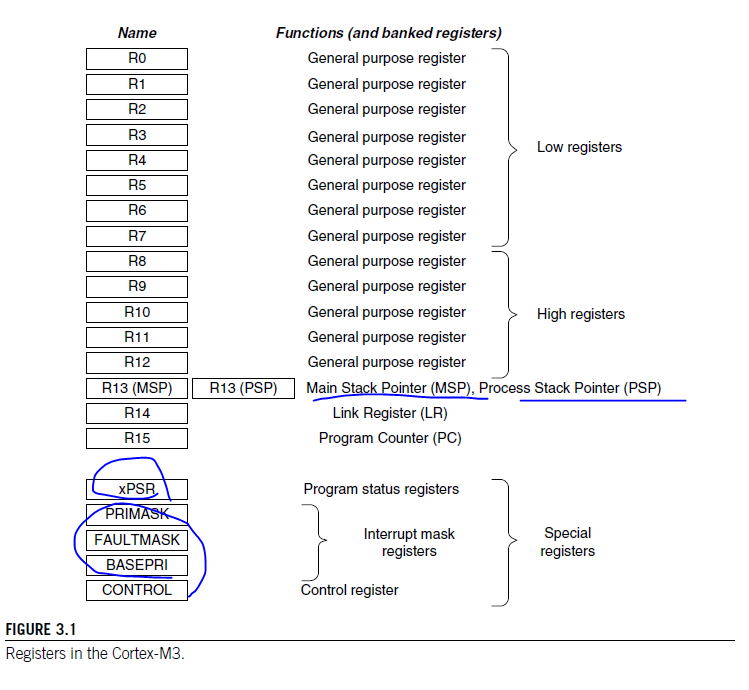
3.1.3 Stack Pointer R13
R13 is the stack pointer(SP). In the Cortex-M3 processor, there are two SPs. This duality allows two separate stack memories to be set up. When using the register name R13. you can only access the current SP; the ohter one is inaccessible unless you use special instructions to move to special register from genenral-purpose register(MSR) and move special register to general purpose register(MRS). The two SPs are as fllow:
• Main Stack Pointer (MSP) 또는 ARM 문서에서는 SP_main으로 표시됩니다. 이것은 기본 SP입니다. 운영체제 (OS) 커널, 예외 처리기 및 권한 있는 애플리케이션 코드에서 사용됩니다.

• Process Stack Pointer (PSP) 또는 ARM 문서에서는 SP_process로 표시됩니다. 이것은 베이스 레벨 애플리케이션 코드에서 사용됩니다. (예외 처리기를 실행하지 않을 때)
STACK PUSH AND POP
Stack is a memory usage model. It is simply part of the system memory, and pointer register( inside the processor) is used to make it work as a first in last out buffer the common use of as stack is to save register contents before some data processing and then restore those contents from the stack after the processing task is done.
Basic Concept of Stack Memory.
When doing PUSH and POP operations, the pointer register, commonly called stack pointer, is adjusted automatically to prevent next stack opertaions from corruption previous stacked data. More details on stack operations are provided on later part of this chapter.
It is not necessary to use both SPs. Simple applications can rely purely on the MSP. The SPs are used for accessing stack memory processes such as PUSH and POP.
In the Cortex-M3, the instructions for accessing stack memory are PUSH and POP. The assembly languate syntax is as follows
PUSH {R0} = r13 = R13-4, then Memory[R13] = R0
POP {R0} : R0 = Memory[$13}. then R13 = R13 + 4
The Cortex usea a full descending stack arrangement. Therefore, the SP decrements when new data is stored in the stack. PUSH and POP are usually used to save register contents to stack memory at the start of a subroutine and then restore the registers from stack at the end of the subroutine. You can PUSH or POP multiple registers in one instruction :
3.1.4 Link Register R14
R14 is the link register (LR). Inside an assembly program, you can write it as either R14 or LR. LR is used to store the return program counter (PC) when a subroutine or function is called -- for example, when you are using the branch and link instrunction
main
...
BL function 1 ; Call function1 using Branch with link instruction
; PC = function 1 and
; LR = the next instruction in main
function 1
... ;
BX LR ; Return
Despite the fact that bit 0 of the PC is always 0 (becasuse instructions are word aligned or half word aligned), The LR bit 0 is readable and writable. This is because in the Thumb instruction set, bit 0 is often used to indicate ARM/Thumb states. To allow the Thumb-2 program for the Cortex-M3 to work with other ARM processors that support the Thumb-2 technology, this least significant bit (LSB) is writable and readable.
3.1.5 Program Counter R15
R15 is the PC. You can access it in assebler code by either R15 or PC. because of pipelined nature of the Cortex, When you read this register, you will find that the value is different than the location of th executing instruction, normally by 4. For example :
0x1000 : MOV R0, PC; R) = 0x1004
In other instructions like literal load(reading of a memory location related to current PC value), the effective value of PC might not be instruction address plus 4 due to alignment in address calculation. But the PC value is still at least 2 bytes ahead of the instruction address during execution.
Cortex-M3 프로세서에서는 프로그램 카운터(PC)를 R15 레지스터로 표현합니다. PC는 다음에 실행할 명령어의 주소를 가리킵니다. 그러나 파이프라인 구조로 인해 PC 레지스터의 값을 읽을 때, 실행 중인 명령어의 위치보다 일반적으로 4바이트(또는 한 개의 명령어)가 앞서 있는 것을 확인할 수 있습니다.Writing to the PC will cause a branch. Because an instruction address must be half word aligned, the LSB(bit 0) of the PC value is always 0. However, in branching either by writing to PC or using branch instructions, the LSB of the target address should be set to 1 because it is used to indicate the Thumb state operations. If it is 0, it can imply trying to switch to the ARM state and will result in a fault exception in the Cortex-M3.
3.2 SPECIAL REGISTERS
The special registers in the Cortex-M3 processor include the following
-
Program Status Registers(PSRs)
-
Interrupt Mask registers(PRIMAKS, FAULTMASK, and BASEPRI)
-
Control register(CONTROL)
Special registers can only be accessed via MSR and MRS instructions; they do not have memory addresses:
MRS , <special_reg> : Read special register
MSR <special_reg>, : write to special register3.2.1 Program Status Registers
The PSRs are subdivided into three status registers :
-
Application Prgram Status register (APSR)
-
Interrupt Program Status register(IPSR)
-
Execution Program Status register(EPSR)
The three PSRs can be accessed together or separately using the special register access instructions MSR and MRS. When they are accessed as a collective itme, the name xPSR is used.
You can read the PSRs using the MRS instruction. You can also change the APSR usint the MSR instruction, but EPSR and IPSR are read-only. For example:
MRS r0, APSR ; Read Flag state into R0
MRS r0, IPSR ; Read Exception / Interrupt state
MRS r0, EPSR ; Read Execution State
MSR APSR, r0 ; Write Flag State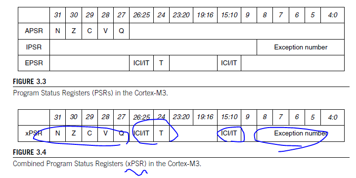
Table 3.1 Bit fields in Cortex-M3 Program Status Registers
Bit Description N Negative Z Zero C Carry/Borrow V Overflow Q Sticky saturation flag ICI/IT Interrupt Continuable Instruction (ICI) bits, IF-Then instruction status bit T Thumb state, always 1; trying to clear this bit will cause a fault exception 3.2.2 PRIMASK, FAULTMASK, and BASERPI
registers are used to disable exceptions.
the PRIMASK and BASEPRI registers are useful for temporarily disabling interrupts in timing critical tasks. An OS could use FAULTMASK to temporarily disable fualt handling when a task has crashed. In this scenario, a number of different faults might be taking place when a task crashes. Once the core starts cleaning up, it maight not want to be interrupted by other faults caused by the crashed process.Therefore, the FAULTMASK gives the OS kernel time to deal with fault conditions.
| Register Name | Description |
|---|---|
| PRIMASK | A 1-bit register, when this is set, it allows nonmaskable interrupt(NMI) and the hard fault exception, Default value is 0, which means that no masking is set |
| FAULTMASK | it allows only the NMI, and all interrupts and fault handling exceptions are disabled. The defaut value is 0, which means that no masking is set. |
| BASEPRI | A register of up to 8bits(depending on the bit width implemented for priority level). it defines the masking priority level. When this is set, it disables all interrupts of the same or lower level(larger priority value). Higher priority interrupts can still be allowed. If this is set to 0, the masking function is disabled(this is the default). |
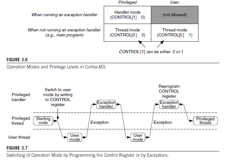
3.2.3 The Control Register
The control register is used to define the privilege level and the SP selection. This register has 2 bits, as shown in Table 3.3.
CONTROL[1]
In the Cortex-M3, the CONTROL[1] bit is always 0 in handler mode. However, in the thread or base level, it can be either 0 or 1.
Table 3.3 Cortex-M3 control Register
| Bit | Function |
|---|---|
| CONTROL[1] | Stack status : 1 = Alternate stack is used 0 = Default stack (MSP) is used if it is in the thread or base level, the alternate stack is the PSP, There is no alternate stack for handler mode, so this bit must be 0 when the processor is in handler mode |
| CONTROL[0] | 0 = Privilegend in thread mode 1 = User state in thread mode If in handler mode(not thread mode), the processor operates in privileged mode |
This bit is writeable only when the core is in thread mode and privileged. In the user state or handler mode, writing to his bit is not allowed. Aside from writing to this register, another way to change this bit is to change bit 2 of the LR when in exception return.
CONTROL[0]
The CONTROL[0] bit is writable only in a privileged state. Once it enters the user state, the only way to switch back to privileged is to trigger an interrupt and change this in the exception handler.
To access the control register in C, the following CMSIS functions are available in CMSIS compliant device diver libraries :
3.3 OPERATION MODE
This supports two modes and two privilege levels.
When the processor is running in thread mode, it can be in either the privileged or user level. but handlers can only be in the privileged level. When the processor exits reset, it is in thread mode, with privileged access rights.
In the user access level(thread mode), access to the system control space(SCS) - a part of the memory region for confuguraion registers and debugging components -- is blocked. Furthermore, instructions that access special registers( such as MSR, except when accessing APSR) cannot be used. If a program running at the user access level tries to access SCS or special registers, a fulat exception will occur.
Software in a privileged access level can switch the program into the user access level using the control register. When an exception takes place, the processor will always switch to a privileged state and return to the previous state when exiting the exception handler. A user program cannot change back to the privileged state directly by writing to the control register.
The support of privileged and user access levels provides a more secure and robust architecture. For example, when a user program goes wrong, iw will not be able to corrupt control registers in the Nested Vectored Interrupt Controller (NVIC). In addotion, if the Memory Protection Unit (MPU) is present, it is possible to block user programs from accessing memory regions used by privileged processes.
In sample applicationm there is no need to separte the privileged and user access levels. In these cases, there is no need to separate the privileged and user access levels. In these cases, there is no need to use user access levle and no need to program the control register.
You can separate the user application stack from the kernel stack memory to avoid the possibility of crashing a system caused by stack operation errors in user programs. With this arrangement, the user program(running in thread mode) uses the PSP, and the exception handlers use the MSP. The switching of SPs is automatic upon entering or leaving the exception handlers(see section 3.6.3). This topic is discussed in more detail in Chapter 8.
The mode and access level of the processor are defined by the control register. When the control register bit 0 is 0, the processor mode changes when an exception takes place.
When control register bit 0 is 1 (thread running user application ), both processor mode and access level change when an exception takes place.
Control register bit 0 is programmable only in the privileged level. For a user-level program to switch to privileged state, it has to raise an interrupt(for example, supervisor call ) and write to CONTROL[0] within the handler.
-> user 영역에서 privilege 영역으로 들어가려면 raise the interrupt 를 해야한다. 예를 들어 SVC !
3.4 EXCEPTIONS AND INTERRUPTS
The Cortex-M3 supports a number of exceptions, including a fixed number of system exceptions and a number of interrupt, commonly called IRQ. The number of interrupt input on a Cortex-M3 microcontroller depends on the individual design. Interrupts generated by peripherals, except System Tick Timer, are also connected to the interrupt input signals. The typical number of interrupt inputs is 16 or 32. However, you might finde some mucrocontroller designs with more (or fewer) interrupt inputs.
Besides the interrupt input, there is also a nonmakable interrupt(NMI) input signals. The actual use of NMI depends on the design of the microcontroller or system-on-chip(SoC) product you use. In most cases, the NMI could be connected to a watchdog timer or a voltage monitoring block that warns the processor when the voltage drops below a certain level. The NMI exception can be activated any time, even right after the core exits reset.
The list of exceptions found in the Cortex-M3
the NVIC also provides a number of fault status registers so the error handlers can determin the cause of the exceptions.
More details on exception operations in the Cortex M3 processor are discussed in Chapters
Exception Types in Cortex-M3
| Exception Number | Exception Type | Prioirity | Fuction |
|---|---|---|---|
| 1 | reset | -3 | reset |
| 2 | NMI | -2 | Nonmaskable interrupt |
| 3 | Hard Fault | -1 | All classes of fault, when the corresponding fault handler cannot be activated because it is currently disabled or masked by exception masking |
| 4 | MemManage | Settable | Memory management fault; cause by MPU violation or invalid accesses(such as an instruciton fetch from a nonexecutale region) |
| 5 | Bus fault | Settable | Usage fault; typical causes are invalid instructions or invalid state transition attempts(such as trying to switch to ARM state in the Cortex-M3) |
| 6 | Usage fault | Settable | Usage fault; typical causes are invalid instructions or invalid state transition attempts(such as trying to switch to ARM state in the Cortex-M3) |
| 7-10 | _ | _ | Reserve |
| 11 | SVC | Settable | Supervisor call via SVC instruction |
| 12 | Debug Monitor | Settable | Debug Monitor |
| 13 | - | - | Reserved |
| 14 | PendSV | Settable | Pendable request for system service |
| 15 | SYSTICK | Settable | System tick timer |
| 16-255 | IRQ | Settable | IRQ input #0-239 |
3.5 VECTOR TABLES
When an exception event takes place on the Cortex-M3 and is accepted by the processor core, the corresponding exception handler is executed. To determine the starting address of the exception handler, a vector table mechanism is used. The vector table is an array of word data inside the system memory, each representing the starting address of one exception type. The vector table is relocatable, and the relocation is controlled by a relocation register in the NVIC. After reset, this relocation control register is reset to 0; therer fore, the vector table is located in address 0x0 after reset.
For example, if the reset is exception type 1, the address of the reset vector is 1 times 4 (each word is 4 bytes), The address 0x00000000 is used to store the starting value for the MSP.
모든 ARM Cortex-M based MCU는 reset 이후 다음과 같이 작동한다.


1. PC(Program Counter)는 0x0000 0000 값을 갖는다.


2. 프로세서는 0x0000 0000의 value를 읽어 MSP(Main Stack Pointer)에 넣는다.

MSP = value@0x0000 0000

즉, 프로세서가 가장 먼저 하는 일은 Stack pointer를 intialize 하는 일이다.


3. 프로세서는 0x0000 0004 의 value를 읽어 PC에 넣는다.

그리고 해당 value는 Reset Handler의 주소이다.


4. PC는 Reset Handler로 점프한다.

Reset Handler는 Application 실행을 위해 필요한 초기화를 하는 C/어셈블리어로 작성된 함수이다.


5. Reset Handler에서 Application의 main()함수를 호출한다.
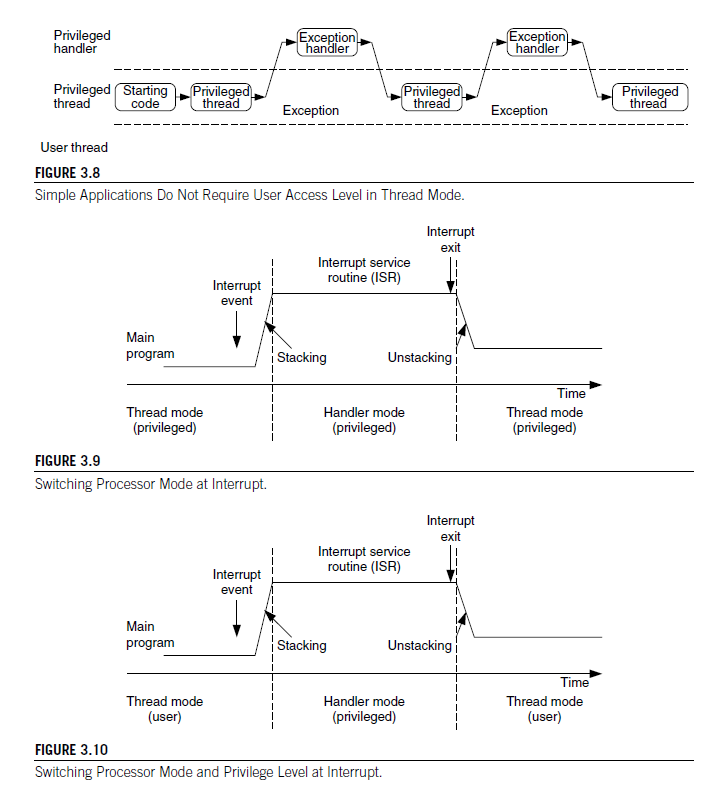
3.6 STACK MEMORY OPERATINONS
In the Cortex-M3, besides normal software-controlled stack PUSH and POP, the stack PUSH and POP opertaions are also carried out automatically when entering or exiting an exception/interrupt handle.
3.6.1 Basic Operations of the Stack
In general, stack opertaions are memory write or read operations, with the address specified by an SP. Data in registers is saved into stack memory by a PUSH operation and can be restored to registers later by POP operation. The SP is adjjusted automatically in PUSH and POP so that multiple data PUSH will not cause old stacked data to be erased.
The function of the stack is to store register contents in memory so that they can be restored later, after a processing task is completed. For normal uses, for each store(PUSH), there must be a correspnding reaD(POP), and the address of the POP opertaion should match that of the PUSH operation. When PUSH/POP instructions are used, the SP is incremented/decremented automaticlly.
When program control returns to the main program, the R0-R2 contents are the same as before. Notice the order of PUSH and POP: The POP order must be the reverse of PUSH.
These operations can be simpified, thanks to PUSH and POP instructions allowing multiple load and store. In this case the ordering of a register POP is automatically reversed by the processor
You can also combine RETURN with a POP operation. This is done by pushing the LR to the stack and popping it back to PC at the end of the subrouting(see Figure 3.13).
스택의 기본 동작에 대한 내용을 설명하는 이 문장은 다음과 같습니다:

스택의 기본 동작:
스택의 동작은 일반적으로 메모리 쓰기 또는 읽기 동작으로 이루어지며, 주소는 SP (스택 포인터)에 의해 지정됩니다. 레지스터에 있는 데이터는 PUSH 동작을 통해 스택 메모리에 저장되며, 나중에 POP 동작을 통해 레지스터로 복원될 수 있습니다. PUSH와 POP에서는 SP가 자동으로 조정되어 여러 데이터 PUSH가 이전에 스택에 저장된 데이터를 지우지 않도록 합니다.

스택의 역할:
스택의 역할은 처리 작업이 완료된 후에 레지스터 내용을 메모리에 저장하여 나중에 복원하는 것입니다. 일반적으로 각 저장(PUSH)에는 해당하는 읽기(POP)가 있어야 하며, PUSH 동작의 주소는 POP 동작과 일치해야 합니다 (Figure 3.11 참조). PUSH/POP 명령을 사용할 때는 SP가 자동으로 증가/감소됩니다.

메모리 주소의 역순 사용:
프로그램 제어가 메인 프로그램으로 반환되면 R0-R2 내용은 이전과 동일합니다. PUSH와 POP의 순서에 주목하세요: POP의 순서는 PUSH의 역순이어야 합니다.

다중 로드와 저장을 허용하는 PUSH와 POP 명령:
다중 레지스터 로드와 저장을 허용하는 PUSH와 POP 명령을 사용하면 작업 순서가 자동으로 뒤집히므로 (Figure 3.12 참조) 작업을 단순화할 수 있습니다.

RETURN과 POP의 결합:
RETURN 동작을 POP 동작과 결합할 수 있습니다. 이를 위해 서브루틴에서 LR (링크 레지스터)를 스택에 PUSH하고 서브루틴의 끝에서 다시 PC (프로그램 카운터)로 POP하는 것이 가능합니다 (Figure 3.13 참조).

이러한 개념과 동작은 스택의 기본 사용 및 조작을 설명하며, 프로그램 실행 중에 레지스터 데이터를 효율적으로 관리하는 데 도움이 됩니다.
3.6.2 Cortex-M3 Stack Implementation.
The Cortex-M3 uses a full-descending stack operation model. The SP points to the last data pushed to the stack memory, and the SP decrements before a new PUSH operation.
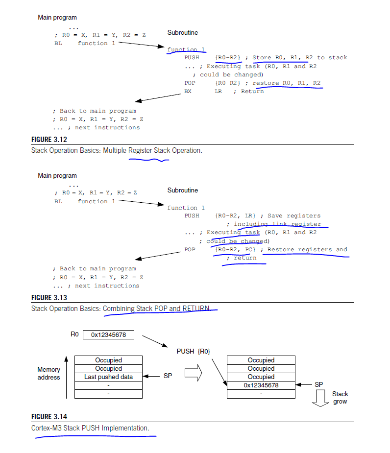
For POP perations, the data is read from the momory location pointer by SP, and then , the SP is incremented. The contents in the memroy location are unchanged but will be overwritten shen the next PUSH operation takes place.
Becuase each PUSH/POP operation transfers 4 bytes of data (each register contains 1 word, or 4 bytes), the SP decrements/increments by 4 at a tiem or a multiple of 4 if more than 1 register is pushed or popped.
In Cortex M3 , R13 is defined at the SP. When an interrupt takes place, a number of regisetrs will be pushed automatically, and R13 will be used as the SP for this stacking process. Similarly, the Pushed registers will be resotred/popped automatically when exiting an interrupt handler, and the SP will also be adjusted.
3.6.3 The Two Stack Model in the Cortex-M3
As mentioned before, the Cortex-M3 has two SPs: the MSPS and the PSP. The SP register to be used is controlled by the control register bit 1 (CONTROL[1] in the following text).
when CONTROL[1] is 0, the MSP is used for both thread mode and handler mode (see Figure 3.16).
In this arragement, the main program and the exception handlers share the same stack memory region. This is the default setting after power-up.
Ehn the CONTROL[1] is 1, the PSP is used in thread mode. In this arragement, the main program and the exception handler can have separate stack memory regions. This can prevent a stack error in a user application from damaging the stack used by the OS(assuming that the user application runs only in thread mode and the OS kernel executes in handler mode).
Note that in this situation, the automatic stacking and unstacking mechanism will use PSP,whereas stack operations inside the handler will use MSP.
it is possible to perform read/write operations directly to the MSP and PSP, without any confusion of which R13 you are referring to , Provided that you are in privileged level, you can access MSP and PSP values:
3.7 RESET SEQUENCE
 After the processor exits reset, it will read two words from memory

 - Address 0x00000000 : Starting value or R13 (the SP )
 - address 0x00000004 : Reset Vector ( the starting address of program execution ; LSB shoud be set to 1 to indicate Thumstate
This differs from tranditional ARM processor behavior. Previous ARM processors executed program code starting from address 0x0. Furthermore, the vector table in previous ARM devies was instructions(you have to put a branch instruction there so that your exception handler can be put in another location);.
In the Cortex-M3, the initial value for the MSP is put at the beginning of the memory map, followed by the vector table, which contain s vector address values( the vector table can be relocated to another location later, during program execution,) In addition, the contents of the vector table are address values not branch instruction.
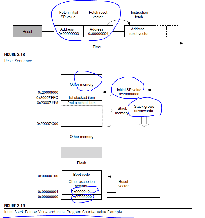
The first vector in the vector table is the reset vector, which is the second piece of data fetched by the processor after reset.
Because the stack operation in ther Cortex-M3 is a full descending stack( SP decrement before store), the initial SP value should be set to the first memory after the top of the stack region. For example, if you have a stack memory range from 0x20007C00 to 0x20007FFF(1KB), the initial stack value should be set to 0x20008000.
The vector tabe starts after the initial SP value. The first vector is the reset vector. Notice that in the Cortex-M3, vector addresses in the vector table should have their LSB set to 1 to indicate that they are Thumb code. For that reasonm the previous example has 0x101 in the reset vector , whereas the boot code starts at addres 0x100. After the rese vector is fetched, the Cortex-M3 can then start to execute the program from the reset vector is fetched, the Cortex-M3 can than start toexecute the program from the reset vector address and begin normal operations. It is necessary to have the SP initialized , becuase some of the exceptions(such as NMI) can happen right after reset, and the stack memory could be required for the handler of those exceptions.
Varioud software development tools might have different way to specify the starting SP value and reset vector.
