Translating and Starting a Program
- 최초 컴퓨터 프로그래머는 machine code를 사용했다.
Machine code는binary code이다.(ex. 1111)Binary code는 사람이 아니라 기계에 의해 읽을 수 있다.- Now, we write programs in languages that other programs translate into machine code
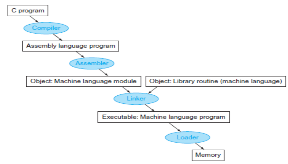
Compiler,Assembler,Linker,Loader
Translation Hierarchy
- high-level language 프로그램을 컴퓨터에서 실행되는 프로그램으로 변환할 때의 4 steps.
- 일부 시스템들은 이 4단계를 통합하거나 줄이기도 한다.
What is "Assembler"?
- 어셈블리 언어를 기계어로 변환시켜주는 시스템 S/W이다.
- 어셈블리어는 기계어가 이해할 수 있는 언어이다.
Object File은 기계어 instruction, 데이터, 그리고 명령어를 메모리에 적절히 배치하는데 필요한 정보를 모아놓은 파일이다.
- 어셈블러가 수행해야할 기본적인 기능들
opcode table을 이용하여 mnemonic operation 코드를 기계어에 해당하는 코드로 번역해준다.- 프로그래머에 의해 사용될 symbolic label들에 machine 주소를 할당한다.
Assembler는 모든 label의 주소를 결정해야 한다.Assembler는symbol table을 통해 Instruction에 사용될label을 추적해야 한다.
Assembler & Its Machine Dependency
- fundamental한 기능들을 생각한다면 대부분
Assembler는 비슷하다. Assembler의 feature와 design은instruction format과addressing mode에 따라 다르다.
-> 이를Machine Dependent Features이라고 한다.
SIC Assembler Language Program(Fig. 2.1, as an example)
Main routine of Fig. 2.1
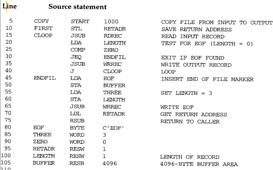
Indexed addressing은 피연산자 뒤에 "X"라는 수식어를 붙여서 표시합니다.STCH BUFFER, X
- "."로 시작하는 줄은 주석만 포함합니다
mnemonic instruction이외에도 다음과 같은directive가 존재.START: 프로그램의 이름과 시작 주소 지정.COPY START 1000
END: 소스 프로그램의 종료를 표시하고 프로그램의 첫 번째 실행 명령을 지정합니다.FIRST STL RETADR
....
END FIRST
BYTE: 상수를 나타내기 위해 필요한 만큼의 바이트를 차지하는 문자 또는 16진수 상수를 생성합니다.EOF BYTE C’EOF’INPUT BYTE X’F1’
WORD: 1 word 크기의 정수 상수를 생성한다.THREE WORD 3
RESB: 데이터 영역에 대해 표시된 바이트 수를 예약.BUFFER RESB 4096
RESW: 데이터 영역에 대해 표시된 워드 수 예약를 예약.RETADR RESW 1
Directive는 기계 명령어로 번역되지 않습니다.- 대신에
Assembler에게instruction을 제공합니다.
- 대신에
- 프로그램은 입력 장치(디바이스 코드
F1)로부터 레코드를 읽고 출력 장치(디바이스 코드05)에 복사하는 메인 루틴을 포함합니다.
- This main routine calls the two subroutines:
RDREC은 버퍼에 레코드를 읽어들인다.WRREC은 버퍼에서 출력 장치로 레코드를 쓴다.
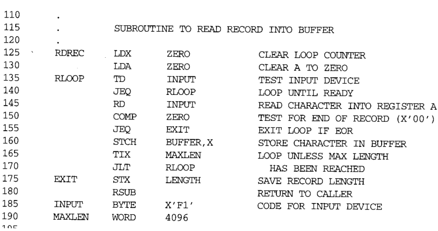
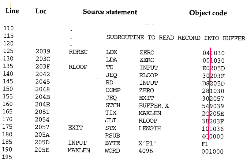
Subroutine RDREC of Fig. 2.1
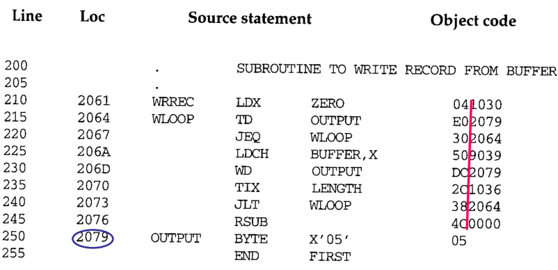
Subroutine WRREC of Fig. 2.1
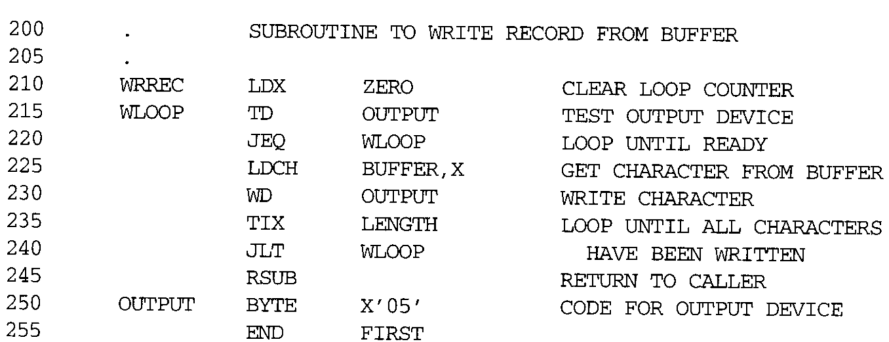
- 사용 가능한
I/O instruction은RD와WD뿐이므로 각Subroutine은 한 번에 한 문자씩 레코드를 전송해야 합니다.- 각 레코드는 여러 개의 문자로 구성됩니다.
- 각 레코드의 끝은
null(16진수 00)로 표시됩니다 - 입력 장치와 출력 장치의 입출력 속도가 다르기 때문에 버퍼가 필요합니다.
- file의 끝을 인식했다면, program은 출력장치에
EOF쓰고RSUBinstruction을 실행하면서 종료된다.- OS에서
JSUB명령을 사용하여 프로그램을 호출했다고 가정한 상황이다. - 그래서
RSUB는OS에control을 돌려준다.
- OS에서
Fig. 2.2: Program from Fig. 2.1 with Object Code
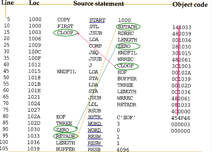
Loccolumn은 assembled program의 각 part에 대한 machine address를 제공한다.- 이 프로그램은 주소 1000번 부터 시작한다고 가정한다.
source program을object code로 변환하는데 필요한 기능들이 있다.:
1) mnemonic operation code를 기계어로 바꾼다.
- Line 10에서
STL을 Object Code14로 변환이 되었다.
2) symbolic 피연산자를 system 주소로 변환
- Line 10에서
RETADDR이1033으로 변환이 되었다. 이때1033이라는 숫자는 아래에 정의된RETADDR의 Loc에서 가져온 것이다.
3) machine instruction을 적절한 format으로 작성한다.
4) 상수 데이터를 시스템 내부 표현으로 변환
- Line 80에서
EOF를454F46으로 변환.
5) object program과 assembly 목록 파일 작성.
- 아래에 나오는 그림 2.3은
Object program을 보여주며 assembly 목록은 그림 2.2와 유사합니다
- 소스 프로그램을 한 줄씩 순차적으로 처리하면 위의 모든 기능을 쉽게 수행할 수 있는데, 주소를 번역하는 두 번째 기능은 문제가 있습니다.
- Consider the statement <line 10> -> This instruction contains a forward reference
이로 인해, 대부분
assembler는 프로그램에 2번의 패스를 진행한다:
- The
1st passlabel에 주소를 할당하는 동안, 원본 프로그램에서 label의 정의를 스캔한다.- The
2nd pass는 이전에 설명한 대부분의 실제 번역이 이루어진다.
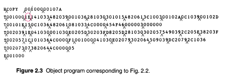
Fig. 2.3: Object Program corresponding to Fig. 2.2
- The assembler must write the generated object code into the object program stored in an output device (i.e., storage), and then this object program will later be loaded into memory for execution.
- The simple object program format used contains 3 types of records:
- Header record contains the program name, starting address, and length
- Text records contain the translated instructions and data of the program, together with an indication of the addresses where these are to be loaded
- End record marks the end of the object program and specifies the address in the program where execution is to begin
Three Types of Records
-
Header record
- Col. 1 H
- Col. 2-7 Program name
- Col. 8-13 Starting address of object program (hex)
- Col. 14-19 Length of object program in bytes (hex)
-
Text record
- Col. 1 T
- Col. 2-7 Starting address for object code in this record (hex)
- Col. 8-9 Length of object code in this record in bytes (hex)
- Col. 10-69 Object code, represented in hex (2 columns per byte of object code)
-
End record
- Col.1 E
- Col.2-7 Address of first executable instruction in object program (hex)
Fig. 2.3
loader가 올려준다.
-
The symbol ^ is used to separate fields visually
- Of course, such symbols are not present in the actual object program
-
Note that there is no object code corresponding to addresses 1033-2038. This storage is simply reserved by the loader for use by the
program during execution.
The Object File for UNIX
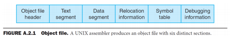
- The object file for UNIX systems typically contains 6 distinct pieces:
- Header, describing the size & position of the other 5 pieces of the object file
- Text Segment, containing the machine language code
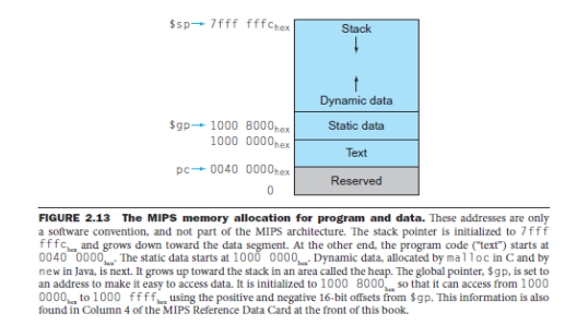
- Static Data Segment, containing data allocated for the life of the program
- UNIX allows programs to use both static data (allocated throughout the program) and dynamic data (which can grow or shrink as needed by the program)
- Relocation Information, identifying instructions and data words that depend on absolute addresses when the program is loaded into memory
- Symbol Table, containing <lable – address> information about function and global variables
- Debugging Information : 디버거가 컴퓨터 명령을 C 소스 파일과 연결할 수 있도록 기호 정보를 포함합니다
- 프로그램 모듈의 컴파일 방법에 대한 간략한 설명이 들어있다.
2-pass Assembler
-
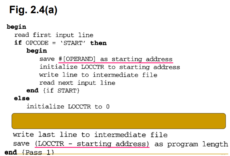
Pass 1: Define symbols
- Read a statement in a line of assembly code
read next input line - Assign an address to this statement: increasing the address by N (byte addressing) using LOCCTR (location counter)
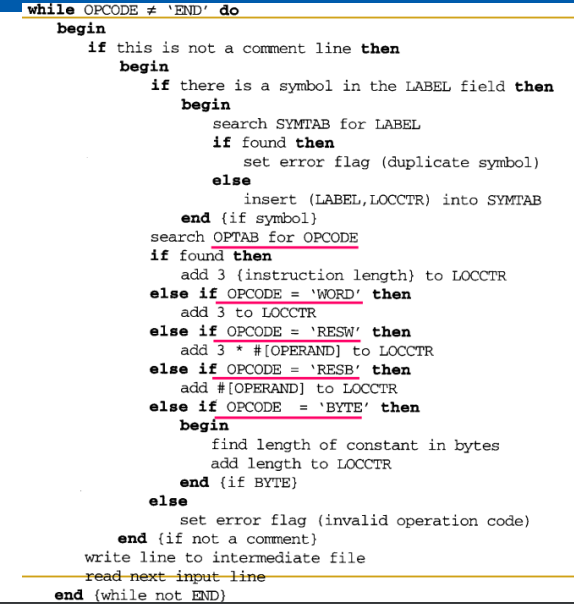
add 3 to LOCCTR - Save address values assigned to all labels (in symbol tables) for use in pass 2
insert {LABEL,LOCCTR} into SYMTAB - Perform some processing of assembler directives, such as constant declaration or space reservation
- This includes processing that affects address assignment, such as determining the length of data areas defined by BYTE, RESW, etc.
- 여기에는 BYTE, RESW 등에 의해 정의된 데이터 영역의 길이를 결정하는 것과 같이 주소 할당에 영향을 미치는 처리가 포함됩니다.
- Read a statement in a line of assembly code
Pass1은 보통 할당된 주소, 오류 지시자 등과 함께 각 소스 문을 포함하는 중간 파일을 작성합니다
FIRST STL RET라는 코드 line을 예시로 용어 정리를 하겠다.
FIRST: LABEL
STL: OPCODE
RET: OPERAND
-
변수 초기화:
initialize LOCCTR to starting address
시작 전에 어셈블러는 초기화를 수행합니다. LOCCTR(위치 카운터)를 프로그램의 시작 주소로 설정하고, 심볼 테이블을 비웁니다. -
소스 코드 읽기:
read next input line
어셈블리 코드를 한 줄씩 읽어나갑니다. -
어셈블러 지시어 처리:
OPCODE ='WORD'
각 줄에서 어셈블러 지시어를 찾습니다. 지시어에 따라 LOCCTR을 조정하고, 상수 선언이나 공간 예약과 같은 특별한 처리를 수행합니다. -
레이블 처리:
insert (LABE,LOCCTR) into SYMTAB
현재 읽고 있는 명령문에 레이블이 있다면 해당 레이블과 현재 LOCCTR 값을 심볼 테이블에 저장합니다.
레이블이 이미 심볼 테이블에 있다면 중복 정의된 레이블에 대한 오류를 발생시킵니다. -
LOCCTR 증가:
add 3 to LOCCTR
LOCCTR을 현재 지시어나 명령문에 따라 적절히 증가시킵니다. 명령어의 길이나 데이터 영역의 크기에 따라 조절될 수 있습니다. -
코드의 끝까지 반복:
소스 코드를 끝까지 읽으면서 각 줄에 대한 처리를 반복합니다. -
중간 결과 저장:
write line to intermediate file
첫 번째 패스가 끝나면 어셈블러는 생성된 심볼 테이블과 다른 중간 결과를 저장합니다
-
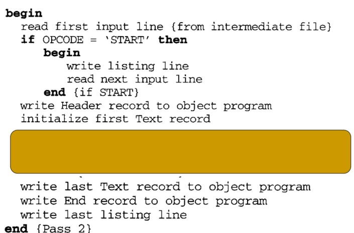
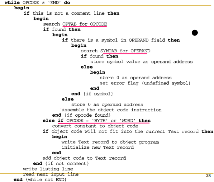
Pass 2: Assemble instructions & generate object program
- Read in a line of code:
read next input line
Intermediate file created in the 1st pass is used as the input to the 2nd pass - Translate operation code: using OP Code Table
search SYMTAB for OPERAND - Change labels to addresses : using Symbol Table
store symbol value as operand address - Perform processing of assembler directives not done during pass 1
- Produce object program
write Text record to object program
write last listing line
- Read in a line of code:
op table에서 opcode를 검색해서 발견이 된 경우, 즉 instruction인지 아닌지 확인하고, instruction을 object code로 translation을 진행하고 발견이 되지 않고 opcode가 byte나 word이면 data를 obejct code로 translation을 진행한다.
Two Data Structures of SIC Assembler
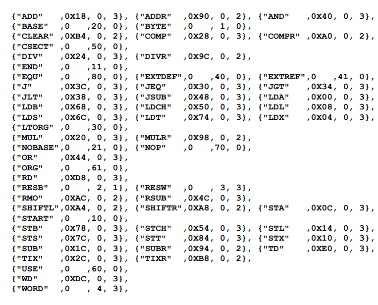
- Operational Code Table (OPTAB)
- Contain mnemonic op code and its machine language equivalent.
- Also, it may contain variable-sized instruction format and length (for more complex assemblers)
- In Pass 1, it is used to look up and validate mnemonic codes.
- 패스 1에서는 mnemonic를 조회하고 검증하는 데 사용됩니다.
- In Pass 2, it is used to translate the assembly code to machine language.
- Pass 2에서 어셈블리 코드를 기계어로 변환하는 데 사용됩니다.
- Usually organized as a hash table
- Key: mnemonic code
- Fast retrieval(검색) with a minimum of searching
- Once prepared, the OPTAB is not changed
- Contain mnemonic op code and its machine language equivalent.
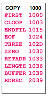
- Symbol Table (SYMTAB)
– Include name and value (address) for each label in the source program, together with flags (error condition).- Also, it may contain other information such as a type or a length for instruction/data labeled.
- In Pass 1, labels are entered into SYMTAB with their assigned addresses (from LOCCTR : location counter).
- In Pass 2, 피연산자로 사용되는 symbol은 SYMTAB에서 검색되어 assembled instruction에 삽입될 주소를 얻습니다.
- Usually hash table
- efficient insertion and retrieval are needed
4계층 외우기
opcode table을 통해서 뭘 하는지
symbol table을 통해서 어셈블러가 뭘 하는지
machine dependent feature
stl retadr 을 하는 이유
어셈블러가 오브젝트 프로그램 만드는 과정 이해하기 1부터 5단계 convert로 시작하고
forward reference가 무엇인지
정의 되지 않는 것을 참조 할때가 forward reference를 해결하기 위해 2-pass를 이용한다.
Fig 2.3 오브젝트 파일에서 각 필드의 의미가 무엇인지 각 텍스트마다.
LOCCTR,
슈도코드에서 무슨일을 하는 것인지..