벡터를 통한 이미지 생성을 해보았다.
그렇다면 이번엔 ray 구조체를 만들고 이 ray를 통해 스크린으로 쏘는 과정을 나타낼 것이다.
이때를 위하여 벡터의 사칙연산, 내적, 외적, 단위벡터, 벡터의 길이를 구하는 공식을 코드로 구현 한다.
벡터의 사칙연산
t_vec           *ft_vec_add(t_vec *new_vec, t_vec *u, t_vec *v)
{
    new_vec->x = u->x + v->x;
    new_vec->y = u->y + v->y;
    new_vec->z = u->z + v->z;
    return (new_vec);
}

t_vec           *ft_vec_sub(t_vec *new_vec, t_vec *u, t_vec *v)
{
    new_vec->x = u->x - v->x;
    new_vec->y = u->y - v->y;
    new_vec->z = u->z - v->z;
    return (new_vec);
}

t_vec           *ft_vec_multi(t_vec *new_vec, t_vec *u, t_vec *v)
{
    new_vec->x = u->x * v->x;
    new_vec->y = u->y * v->y;
    new_vec->z = u->z * v->z;
    return (new_vec);
}

t_vec           *ft_vec_div(t_vec *new_vec, t_vec *u, t_vec *v)
{
    new_vec->x = u->x / v->x;
    new_vec->y = u->y / v->y;
    new_vec->z = u->z / v->z;
    return (new_vec);
}

t_vec           *ft_vec_multi_double(t_vec *new_vec, double t, t_vec *v)
{
    new_vec->x = v->x * t;
    new_vec->y = v->y * t;
    new_vec->z = v->z * t;
    return (new_vec);
}

t_vec           *ft_vec_div_double(t_vec *new_vec, double t, t_vec *v)
{
    new_vec->x = v->x / t;
    new_vec->y = v->y / t;
    new_vec->z = v->z / t;
    return (new_vec);
}
벡터의 내적, 외적
double          ft_vec_dot(t_vec *u, t_vec *v)
{
    return (u->x * v->x + u->y * v->y + u->z * v->z);
}

t_vec           *ft_vec_cross(t_vec *new_vec, t_vec *u, t_vec *v)
{
    new_vec->x = u->y * v->z - u->z * v->y;
    new_vec->y = u->z * v->x - u->x * v->z;
    new_vec->z = u->x * v->y - u->y * v->x;
    return (new_vec);
}
벡터의 기타 계산식
double          ft_vec_len(t_vec *new_vec)
{
    return (sqrt(ft_vec_len_sqrt(new_vec)));
}

double          ft_vec_len_sqrt(t_vec *new_vec)
{
	return (pow(new_vec->x, 2.0) + pow(new_vec->y, 2.0) + pow(new_vec->z, 2.0));
}

t_vec           *ft_vec_unit(t_vec *new_vec, t_vec *v)
{
    return (ft_vec_div_double(new_vec, ft_vec_len(v), v));
}
그리고 광선을 정의할 구조체와 함수를 만든다.
typedef t_vec t_point;
typedef t_vec t_color;

typedef struct  s_ray
{
    t_point     orig;
    t_vec       dir;
}               t_ray;
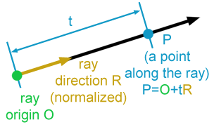
(사진: https://www.scratchapixel.com/lessons/3d-basic-rendering/ray-tracing-generating-camera-rays)
그림으로 알아보자면,
여기서 orig는 origin으로 처음 위치를 뜻한다.
그리고 dir는 direction으로 눈이 어느한 곳을 응시할 때 그 응시하는 방향을 뜻한다.
그러므로 orig는 시작포인트로 O라고 하고 dir는 거리를 나타내어 R, t는 거리의 길이같은 것이고, 광선의 한지점을 라 한다.
이 모든 것을 수식으로 나타내면 이 되는 것이다.
그리고 이것을 코드로 나타내면
t_point     *ft_ray_hat(t_point *new_ray, t_ray *ray, double t)
{
    new_ray->x = ray->orig.x + t * ray->dir.x;
    new_ray->y = ray->orig.y + t * ray->dir.y;
    new_ray->z = ray->orig.z + t * ray->dir.z;
    return (new_ray);
}
가 되고, 그러면 ray의 출발점, ray가 비추는 거리가 존재하게 된다.
그러면 이제 우리가 바라보는 시점을 만들어야하기에 카메라 함수를 만들어야 한다.
레이 트레이싱을 구현하기 위해선 광선만 있으면 안된다.
아무리 안보이는 곳에서 광선이 돌아다녀도 그것을 관찰할 수 없다면 그게 다 무슨 소용이란 말인가.
그러면 레이 트레이싱을 구현하려면 어떠한 과정이 필요할까?
- 카메라(눈)에서 픽셀까지의 광선을 계산한다.
- 광선이 부딪치는 오브젝트들을 결정한다.
- 광선이 부딪친 위치의 색을 계산한다.
void        ft_camera_create(t_camera *cam, double aspect_ratio)
{
    cam->viewport_h = 4.0;
    cam->viewport_w = aspect_ratio * cam->viewport_h;
    cam->focal_length = 2.0;
    ft_vec_create(&cam->origin, 0.0, 0.0, 0.0);
    ft_vec_create(&cam->horizontal, cam->viewport_w, 0.0, 0.0);
    ft_vec_create(&cam->vertical, 0.0, cam->viewport_h, 0.0);
    cam->lower_left_corner.x = cam->origin.x - (cam->horizontal.x / 2)
    - (cam->vertical.x / 2) - 0;
    cam->lower_left_corner.y = cam->origin.y - (cam->horizontal.y / 2)
    - (cam->vertical.y / 2) - 0;
    cam->lower_left_corner.z = cam->origin.z - (cam->horizontal.z / 2)
    - (cam->vertical.z / 2) - cam->focal_length;
}
카메라의 초기값을 지정하여 만든다. 그리고 계산할 픽셀의 위치인 lower_left_corner의 벡터를 구한다.
t_ray       *ft_camera_ray_cal(t_ray *new_ray, t_camera *cam, double u, double v)
{
    t_vec cal;

    cal.x = cam->lower_left_corner.x + u*cam->horizontal.x + v*cam->vertical.x
            - cam->origin.x;
    cal.y = cam->lower_left_corner.y + u*cam->horizontal.y + v*cam->vertical.y
            - cam->origin.y;
    cal.z = cam->lower_left_corner.z + u*cam->horizontal.z + v*cam->vertical.z
            - cam->origin.z;
    return (ft_ray_create(new_ray, &(cam->origin), &cal));
}
lower_left_corner를 기준으로 매개변수 u,v값의 비율로 스크린 상의 해당 지점까지의 광선을 구한다. 그리고 구한 광선을 토대로 픽셀의 색을 정하는데 정규화시킨 광선의 t축 성분 크기의 비율로 배경의 색상을 정한다.
t_color *ft_ray_color(t_color *new_ray, t_ray *r)
{
double t;
t_vec unit_dir;
t_color cal1;
t_color cal2;
ft_vec_unit(&unit_dir, &(r->dir));
t = 0.5 * (unit_dir.y + 1.0);
ft_vec_multi_double(&cal1, (1.0 - t), ft_vec_create(&cal1, 1.0, 1.0, 1.0));
ft_vec_multi_double(&cal2, t, ft_vec_create(&cal2, 0.5, 0.7, 1.0));
return (ft_vec_add(new_ray, &cal1, &cal2));
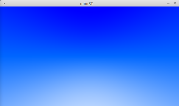
}최종적으로는 아래와 같은 화면이 나온다.
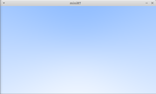
다른 색으로 하려면 t를 바꿔주면 된다.