아래 글에서 각 모듈을 구현하여 검증하였다.
- https://velog.io/@pikamon/Verilog-10 (Baudrate Generator)
- https://velog.io/@pikamon/Verilog-11 (Receiver)
- https://velog.io/@pikamon/Verilog-12 (Transmitter)
이제 각 모듈을 Top 모듈에서 인스턴스화한 다음 wire로 이어보자.
1. RTL 구현
구현한 Top 모듈은 아래와 같다.
앞에서 구현한 세 모듈을 include로 가져온 후 생성한다.
- Uart8.v
`ifndef __UART_V__
`define __UART_V__

`include "inc/Defines.vh"
`include "src/BaudRateGenerator.v"
`include "src/Uart8Receiver.v"
`include "src/Uart8Transmitter.v"

module Uart8 #(
        parameter CLOCK_RATE   = `CLOCK_RATE_100MHZ, // board internal clock
        parameter BAUD_RATE    = `BAUD_RATE_115200,  // use 115200 as default
        parameter OVERSAMPLING = `OVERSAMPLING_16,   // use 16x as default
        parameter DATA_BITS    = `DATA_BITS_8        // use 8bit as default
    )(
        input wire clk,

        // rx interface
        input wire rx,
        input wire rxEn,
        output wire [DATA_BITS - 1:0] out,
        output wire rxDone,
        output wire rxBusy,
        output wire rxErr,

        // tx interface
        output wire tx,
        input wire txEn,
        input wire txStart,
        input wire [DATA_BITS - 1:0] in,
        output wire txDone,
        output wire txBusy
    );

    wire rxClk;
    wire txClk;

    BaudRateGenerator #(
        .CLOCK_RATE(CLOCK_RATE),
        .BAUD_RATE(BAUD_RATE),
        .OVERSAMPLING(OVERSAMPLING)
    ) generatorInst (
        .clk(clk),
        .rxClk(rxClk),
        .txClk(txClk)
    );

    Uart8Receiver #(
        .OVERSAMPLING(OVERSAMPLING),
        .DATA_BITS(DATA_BITS)
    ) rxInst (
        .clk(rxClk),
        .en(rxEn),
        .in(rx),
        .out(out),
        .done(rxDone),
        .busy(rxBusy),
        .err(rxErr)
    );

    Uart8Transmitter #(
        .DATA_BITS(DATA_BITS)
    ) txInst (
        .clk(txClk),
        .en(txEn),
        .start(txStart),
        .in(in),
        .out(tx),
        .done(txDone),
        .busy(txBusy)
    );

endmodule

`endif /*__UART_V__*/
수신기의 입출력 라인과 송신기의 입출력 라인이 모두 Top 모듈 밖으로 나와있다.
2. Testbench 구현
테스트벤치를 만들어 보자.
- Uart8_tb.v
`timescale 10ns/1ns

`include "inc/Defines.vh"
`include "src/Uart8.v"

module tbUart8();

	parameter CLOCK_RATE   = `CLOCK_RATE_100MHZ;
	parameter BAUD_RATE    = `BAUD_RATE_115200;
	parameter OVERSAMPLING = `OVERSAMPLING_16;
	parameter DATA_BITS    = `DATA_BITS_8;

    //localparam MAX_RATE_RX = CLOCK_RATE / (2 * BAUD_RATE * OVERSAMPLING);
    //localparam MAX_RATE_TX = CLOCK_RATE / (2 * BAUD_RATE);
	//localparam CLOCK_RX = MAX_RATE_RX * OVERSAMPLING * 2;
	//localparam CLOCK_TX = MAX_RATE_TX * 2;
	localparam CLOCK_RX = CLOCK_RATE / BAUD_RATE;
	localparam CLOCK_TX = CLOCK_RATE / BAUD_RATE;

	reg clk = 0;
	wire [DATA_BITS - 1:0] in;
	wire [DATA_BITS - 1:0] out;

	// rx interface
	reg rx = 1;
	reg rxEn = 1;
	wire rxDone;
	wire rxBusy;
	wire rxErr;

	// tx interface
	wire tx;
	reg txEn = 1;
	reg txStart = 0;
	wire txDone;
	wire txBusy;

	assign in = out;

	Uart8 #(
        .CLOCK_RATE(CLOCK_RATE),
        .BAUD_RATE(BAUD_RATE),
        .OVERSAMPLING(OVERSAMPLING),
        .DATA_BITS(DATA_BITS)
	) test (
		.clk(clk),
        .rx(rx),
        .rxEn(rxEn),
        .out(out),
        .rxDone(rxDone),
        .rxBusy(rxBusy),
        .rxErr(rxErr),

        .tx(tx),
        .txEn(txEn),
        .txStart(txStart),
        .in(in),
        .txDone(txDone),
        .txBusy(txBusy)
	);

	initial begin
		$dumpfile("test.vcd");
		$dumpvars(-1, test);
    end

	initial begin
		begin // (0x55)
			// rx
			#CLOCK_RX rx = 0; // start bit

			#CLOCK_RX rx = 1; // data bit (0x55)
			#CLOCK_RX rx = 0;
			#CLOCK_RX rx = 1;
			#CLOCK_RX rx = 0;
			#CLOCK_RX rx = 1;
			#CLOCK_RX rx = 0;
			#CLOCK_RX rx = 1;
			#CLOCK_RX rx = 0;

			#CLOCK_RX rx = 1; // stop bit

			// tx
			#CLOCK_TX txStart <= 1'b1;
			#CLOCK_TX txStart <= 1'b0;

			#CLOCK_TX; // start bit
			#CLOCK_TX; // data bit
			#CLOCK_TX;
			#CLOCK_TX;
			#CLOCK_TX;
			#CLOCK_TX;
			#CLOCK_TX;
			#CLOCK_TX;
			#CLOCK_TX;
			#CLOCK_TX; // stop bit
		end

		begin // (0x96)
			// rx
			#CLOCK_RX rx = 0; // start bit

			#CLOCK_RX rx = 0; // data bit (0x96)
			#CLOCK_RX rx = 1;
			#CLOCK_RX rx = 1;
			#CLOCK_RX rx = 0;
			#CLOCK_RX rx = 1;
			#CLOCK_RX rx = 0;
			#CLOCK_RX rx = 0;
			#CLOCK_RX rx = 1;

			#CLOCK_RX rx = 1; // stop bit

			// tx
			#CLOCK_TX txStart <= 1'b1;
			#CLOCK_TX txStart <= 1'b0;

			#CLOCK_TX; // start bit
			#CLOCK_TX; // data bit
			#CLOCK_TX;
			#CLOCK_TX;
			#CLOCK_TX;
			#CLOCK_TX;
			#CLOCK_TX;
			#CLOCK_TX;
			#CLOCK_TX;
			#CLOCK_TX; // stop bit
		end
	end

	always begin
		#0.5 clk = ~clk;
	end

	initial begin
		#50000 $finish;
	end

endmodule
수신기에서 출력한 data 라인을 송신기에 입력으로 주어 루프백 형태로 구현하였다.
rx 라인으로 0x55, 0x96에 해당되는 UART 신호를 입력한 후, 수신기와 송신기를 거쳐 다시 tx 라인으로 동일한 신호가 나오는지 확인하면 된다.
3. Makefile 정의
개발 편의를 위해 Makefile을 생성하였다.
- Makefile
all: Uart8

Uart8: clean
	iverilog -o test.vvp testbench/Uart8_tb.v
	vvp test.vvp
	gtkwave test.vcd

clean:
	rm -f test.vcd
	rm -f test.vvp
make만 입력하면 자동으로 clean 후 시뮬레이션을 돌릴 수 있다.
4. 실행 및 결과
make를 입력한다.
make그러면 gtkwave가 실행되며, waveform을 확인할 수 있는데,
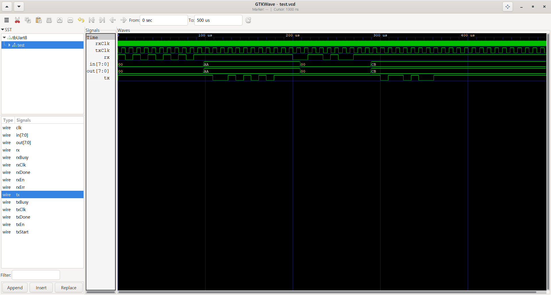
현재 수신기에서 데이터를 잘못 인식하는 버그가 있어서 수정이 필요하다.
맨 앞 비트 하나를 건너뛰는 것 같은데, 확인 후 수정 예정.

개발자입니당 *^^* 깃허브 https://github.com/pikamonvvs