그림자를 만드는법임
이제 좀 어려운거 나온다 이거이거 클났노
그림자를 다루는 알고리즘은 있긴한데
real time rendering에서 잘 사용되지는 않음
그래서 사용하는게 shadow mapping리는 테크닉임
shadow mapping이라는 테크닉을 사용하면
더 고급기술인 omnidirectional shadow mapping(전방향 그림자 매핑), cascade shadow mapping이라는 그림자 매핑 기술로 확장가능함
shadow mapping
아이디어 진짜 간단함
빛(광원)에서 빛이 쏴진 후, 해당 빛이 닿는 지점의 뒷부분에 있는 곳에는 모두 그림자가 생기도록 하면 됨
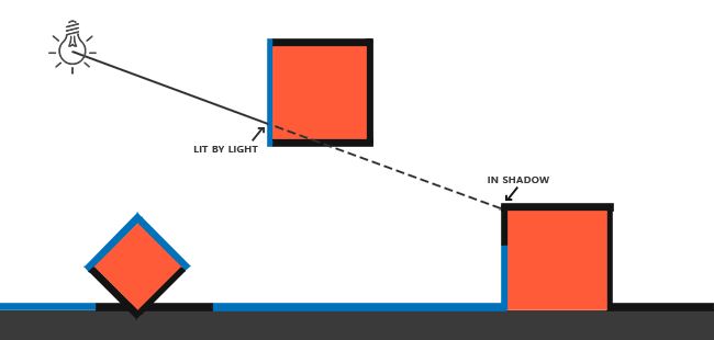
이런거임ㅇㅇ
근데 광원에서 닿을 수 있는 모든곳에 ray를 쏴서 닿는 지점을 판단하고
그 뒷부분에 있는곳은 따로 저장해서 그림자가 생기도록 한다는건
정확도는 높을지언정 너무 무겁고 비효율적이게 됨
우리가 사용할건 깊이임
깊이 테스트에서 우리는 화면에 출력될 fragment를 어떻게 결정짓는지 공부했음
0-1사이의 정규화된 깊이값(z index가 낮을수록 더 높은 정밀도를 가지는 비선형적 깊이테스팅)이 존재하고,
더 높은 우선순위를 가지는 fragment를 출력하는거임
그럼 shadow mapping은 어떻게 이걸 사용하냐?
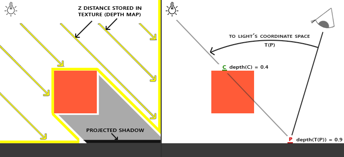
위 사진을 보면서 아래를 읽어보자
- 광원에서의 깊이 테스팅 결과를 depth map, shadow map이라고 부르는 텍스쳐에 저장함
- 우리 화면에 출력되는 fragment의 특정 점을 라고 부름
- 사용자 시야~점의 방향을 transform을 이용해 광원 좌표로 이동시킴
- 광원에서 점까지의 벡터로 바뀜
- depth map을 이용해 해당 벡터에서 z index가 더 높은게 있다면 점에 해당되는 fragment는 그림자가 생김
depth map을 이용해 그림자 계산 예시
depth map/shadow map이라는 텍스쳐를 사용해서 화면에 출력해야함
그럼 커스텀 프레임버퍼를 만들어서 거기에 붙여서 약간 후처리 느낌으로 동작하게 해야함
1. depth map/depth map fbo 만들기
const unsigned int SHADOW_WIDTH = 1024, SHADOW_HEIGHT = 1024;
unsigned int depthMapFBO;
glGenFramebuffers(1, &depthMapFBO);
// create depth texture
unsigned int depthMap;
glGenTextures(1, &depthMap);
glBindTexture(GL_TEXTURE_2D, depthMap);
glTexImage2D(GL_TEXTURE_2D, 0, GL_DEPTH_COMPONENT, SHADOW_WIDTH, SHADOW_HEIGHT, 0, GL_DEPTH_COMPONENT, GL_FLOAT, NULL);
glTexParameteri(GL_TEXTURE_2D, GL_TEXTURE_MIN_FILTER, GL_NEAREST);
glTexParameteri(GL_TEXTURE_2D, GL_TEXTURE_MAG_FILTER, GL_NEAREST);
glTexParameteri(GL_TEXTURE_2D, GL_TEXTURE_WRAP_S, GL_REPEAT);
glTexParameteri(GL_TEXTURE_2D, GL_TEXTURE_WRAP_T, GL_REPEAT);
// attach depth texture as FBO's depth buffer
glBindFramebuffer(GL_FRAMEBUFFER, depthMapFBO);
glFramebufferTexture2D(GL_FRAMEBUFFER, GL_DEPTH_ATTACHMENT, GL_TEXTURE_2D, depthMap, 0);
glDrawBuffer(GL_NONE);
glReadBuffer(GL_NONE);
glBindFramebuffer(GL_FRAMEBUFFER, 0);- depth map전용 그림자 해상도를 설정
- depth map 부착용 프레임버퍼 생성
- depth map텍스쳐 생성후 depth map 부착용 프레임버퍼에 부착
- 단순히 깊이버퍼 정보만 필요하므로 컬러버퍼용 읽기/그리기는 모두
GL_NONE으로 비활성화(색상 렌더링 안함)
그리고 이제 fragment를 특정 공간으로 이동시켜
depth map을 통해 색상을 결정지어야함
2. 빛 크기, 방향 계산
glm::vec3 lightPos = glm::vec3 lightPos(-2.0f, 4.0f, -1.0f);

//1
float near_plane = 1.0f, far_plane = 7.5f;
glm::mat4 lightProjection = glm::ortho(-10.0f, 10.0f, -10.0f, 10.0f, near_plane, far_plane);

//2
glm::mat4 lightView = glm::lookAt(glm::vec3(-2.0f, 4.0f, -1.0f),
                                  glm::vec3( 0.0f, 0.0f,  0.0f),
                                  glm::vec3( 0.0f, 1.0f,  0.0f));

//3
glm::mat4 lightSpaceMatrix = lightProjection * lightView;- 원근투영으로 그림자를 위한 depth를 계산하면 왜곡이 생김
따라서 직교 투영으로 모두 원본 크기에서의 그림자용 depth를 계산할거임- 일정한 near와 far frustum을 이용해 직교투영
- 빛의 닿는 영역을 정의
- lookAt을 이용해 빛이 바라보는 방향을 정의함
- 1번과 2번행렬의 곱을 이용해 특정 world좌표를 빛이 닿는 영역내부로 clipping해주는 광원용 clip공간 변환행렬로 만들어줌
- 사실 쉐이더로 그냥 넘겨도 되는데, 저 값은 일단 변하지 않는 값이라, fragment계산시에 부하 줄이기 위해서 cpu에서 연산 후 넘김
3. depth map용 쉐이더
vertex shader
#version 330 core
layout (location = 0) in vec3 aPos;

uniform mat4 lightSpaceMatrix;
uniform mat4 model;

void main()
{
    gl_Position = lightSpaceMatrix * model * vec4(aPos, 1.0);
}
단순하게 모든 정점을 우리가 정의한
빛 절두체, 빛 방향인 광원 공간으로 이동시킴
fragment shader
#version 330 core

void main()
{
    // gl_FragDepth = gl_FragCoord.z;
}
해당 정점들의 z index를 정의해주면 되는데,
사실 자동으로 적용되어서 크게 의미없는 코드뭉치
4. depth map 적용
// 1. 먼저 깊이 맵으로 렌더링
glViewport(0, 0, SHADOW_WIDTH, SHADOW_HEIGHT);
glBindFramebuffer(GL_FRAMEBUFFER, depthMapFBO);
    glClear(GL_DEPTH_BUFFER_BIT);
    ConfigureShaderAndMatrices();
    RenderScene();
glBindFramebuffer(GL_FRAMEBUFFER, 0);- glViewPort로 그림자 해상도를 먼저 설정해줌
- 그림자 맵 FBO바인딩
- 기본적으로 depth를 이용해서 그림자 map을 정의하므로 매프레임 depth 초기화
ConfigureShaderAndMatrices는 임의의 쉐이더 사용, uniform, 값 설정 로직이 들어가면 됨- 원하는 씬을 렌더링 해주면 자동적으로 depth map FBO에 깊이값이 저장될거임
5. 텍스쳐 부착을 통해 전체 화면(quad) 렌더링
vertex shader
#version 330 core
layout (location = 0) in vec3 aPos;
layout (location = 1) in vec2 aTexCoords;

out vec2 TexCoords;

void main()
{
    TexCoords = aTexCoords;
    gl_Position = vec4(aPos, 1.0);
}
depth map렌더링이 끝난 텍스쳐 부착해야하니 설정
fragment shader
#version 330 core
out vec4 FragColor;

in vec2 TexCoords;

uniform sampler2D depthMap;
uniform float near_plane;
uniform float far_plane;

// required when using a perspective projection matrix
float LinearizeDepth(float depth)
{
    float z = depth * 2.0 - 1.0; // Back to NDC
    return (2.0 * near_plane * far_plane) / (far_plane + near_plane - z * (far_plane - near_plane));
}

void main()
{
    float depthValue = texture(depthMap, TexCoords).r;
    // FragColor = vec4(vec3(LinearizeDepth(depthValue) / far_plane), 1.0); // perspective
    FragColor = vec4(vec3(depthValue), 1.0); // orthographic
}
일단은 간단하게 texture()를 이용해서 렌더링되어 texture 부착을 위해 들어온 depth map을 이용해 TexCoord좌표로 매핑한 후, r값만을 이용해 색상을 결정지을거임
디버그용 렌더로직
glViewport(0, 0, SCR_WIDTH, SCR_HEIGHT);
glClear(GL_COLOR_BUFFER_BIT | GL_DEPTH_BUFFER_BIT);

// render Depth map to quad for visual debugging
// ---------------------------------------------
ConfigureShaderAndMatrices();
renderQuad();
그림자 해상도에서 스크린해상도로 바꿔준후
출력되는건 color와 depth니까 두개 프레임마다 초기화
shader에 들어갈 변수들 설정해주고
quad를 렌더하면....
6. 중간 결과
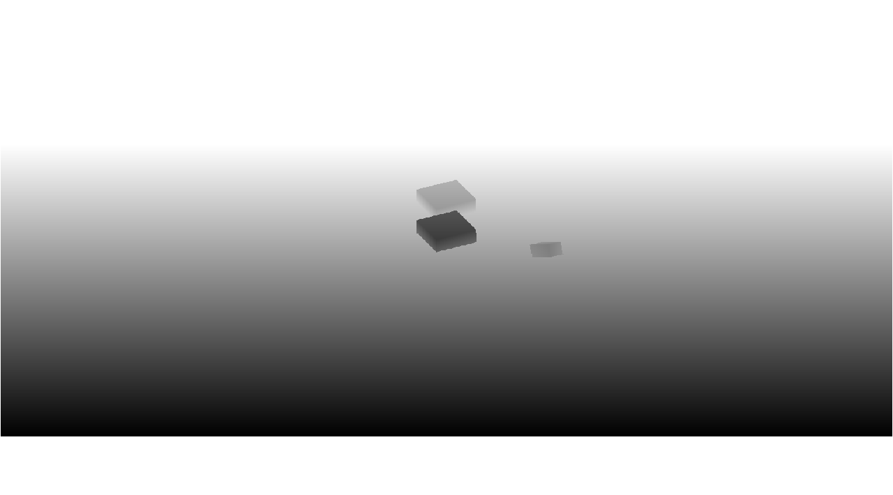
일단 뭔가 까만거하고 머시기 출력되긴함!
7. 그림자 렌더링
이제 위에서 계산한 depth map으로 그림자를 렌더링해볼 차례임
쉐이더 추가하고 값만 넣어주면 됨
vertex shader
#version 330 core
layout (location = 0) in vec3 aPos;
layout (location = 1) in vec3 aNormal;
layout (location = 2) in vec2 aTexCoords;

out vec2 TexCoords;

out VS_OUT {
    vec3 FragPos;
    vec3 Normal;
    vec2 TexCoords;
    vec4 FragPosLightSpace;
} vs_out;

uniform mat4 projection;
uniform mat4 view;
uniform mat4 model;
uniform mat4 lightSpaceMatrix;

void main()
{
    vs_out.FragPos = vec3(model * vec4(aPos, 1.0));
    vs_out.Normal = transpose(inverse(mat3(model))) * aNormal;
    vs_out.TexCoords = aTexCoords;
    vs_out.FragPosLightSpace = lightSpaceMatrix * vec4(vs_out.FragPos, 1.0);
    gl_Position = projection * view * model * vec4(aPos, 1.0);
}
뭔가 복잡해보이는데 걱정하지 말자
일단 핵심 아이디어는 광원 공간과 실제 오브젝트 정점의 공간을 각각 계산해서 fragment shader로 넘기는거임
- VS_OUT에서 눈여겨 봐야할건 FragPosLightSpace임
아까 위 3번에서 depth map용 쉐이더 vertex shader쪽에서 광원공간으로 이동시키는걸 설명했음
그냥 그림자 계산용인거임ㅇㅇㅇ - 그 외 VS_OUT의 변수들은 blinn phong모델을 적용하기 위해 필요한 준비물임
- 오브젝트 정점들의 공간을 먼저 광원공간으로 이동시켜서 그림자 계산에 이용
- 그림자 용이 아닌 오브젝트의 정점은 스크린공간으로 따로 이동
fragment shader
이제 fragment shader를 살펴보자
해줘야하는건 그림자 계산 + original fragment색상 계산임
#version 330 core
out vec4 FragColor;

in VS_OUT {
    vec3 FragPos;
    vec3 Normal;
    vec2 TexCoords;
    vec4 FragPosLightSpace;
} fs_in;

uniform sampler2D diffuseTexture;
uniform sampler2D shadowMap;

uniform vec3 lightPos;
uniform vec3 viewPos;

float ShadowCalculation(vec4 fragPosLightSpace)
{
    // perform perspective divide
    vec3 projCoords = fragPosLightSpace.xyz / fragPosLightSpace.w;
    // transform to [0,1] range
    projCoords = projCoords * 0.5 + 0.5;
    // get closest depth value from light's perspective (using [0,1] range fragPosLight as coords)
    float closestDepth = texture(shadowMap, projCoords.xy).r;
    // get depth of current fragment from light's perspective
    float currentDepth = projCoords.z;
    // check whether current frag pos is in shadow
    float shadow = currentDepth > closestDepth  ? 1.0 : 0.0;

    return shadow;
}

void main()
{
    vec3 color = texture(diffuseTexture, fs_in.TexCoords).rgb;
    vec3 normal = normalize(fs_in.Normal);
    vec3 lightColor = vec3(0.3);
    // ambient
    vec3 ambient = 0.3 * lightColor;
    // diffuse
    vec3 lightDir = normalize(lightPos - fs_in.FragPos);
    float diff = max(dot(lightDir, normal), 0.0);
    vec3 diffuse = diff * lightColor;
    // specular
    vec3 viewDir = normalize(viewPos - fs_in.FragPos);
    float spec = 0.0;
    vec3 halfwayDir = normalize(lightDir + viewDir);
    spec = pow(max(dot(normal, halfwayDir), 0.0), 64.0);
    vec3 specular = spec * lightColor;

    // calculate shadow
    float shadow = ShadowCalculation(fs_in.FragPosLightSpace);
    vec3 lighting = (ambient + (1.0 - shadow) * (diffuse + specular)) * color;

    FragColor = vec4(lighting, 1.0);
}
main의 //calculate shadow주석 전까지는 전형적인 블린 퐁 모델 구현임
색상 계산은 아니고, 색상의 ambient, diffuse, specular의 강도를 구한거임
이제 ShadowCalculate를 통해 계산한 그림자색상과 합쳐서 색상을 결정지을거임
ShadowCalculate메서드
float ShadowCalculation(vec4 fragPosLightSpace)
{
    // perform perspective divide
    vec3 projCoords = fragPosLightSpace.xyz / fragPosLightSpace.w;
    // transform to [0,1] range
    projCoords = projCoords * 0.5 + 0.5;
    // get closest depth value from light's perspective (using [0,1] range fragPosLight as coords)
    float closestDepth = texture(shadowMap, projCoords.xy).r;
    // get depth of current fragment from light's perspective
    float currentDepth = projCoords.z;
    // check whether current frag pos is in shadow
    float shadow = currentDepth > closestDepth  ? 1.0 : 0.0;

    return shadow;
}
천천히 봐보자
무서울거 없음
- FragPosLightSpace는 정점들이 우리가 정의한 광원공간으로 변환된 좌표임
- FragPosLightSpace의 xyz를 w로 나누어서 원근가중치를 줌
- 2번의 결과는 -1~1사이의 값이므로, 0~1사이의 읽을수있는 좌표로 이동
- 3번의 정규화된 좌표로 이동된 정점좌표를 이용해 uniform으로 입력받은 depth map을 매핑해서 텍스쳐로 사용
- 이렇게 해서 나온 텍스쳐는 화면에 그려지는 텍스쳐이므로 화면에 표현되는, 즉, 가장 가까운 좌표를 의미하므로 해당 텍스쳐의 r값을 이용해 depth를 가져옴(어짜피 xyz 똑같음, 흑백이미지라 ㅇㅇ)
- 2번 원근가중치가 섞인 정점좌표의 z축과 비교
- 4번이 크면 0, 5번이 크면 1을 반환
이제 왜 1, 0을 반환하는지는 밑의 로직을 봐보자
그림자 계산 완성
// calculate shadow
float shadow = ShadowCalculation(fs_in.FragPosLightSpace);
vec3 lighting = (ambient + (1.0 - shadow) * (diffuse + specular)) * color;
만약 현재 좌표가 광원 공간 텍스쳐에 가려진 depth를 가지고 있다면 1이 반환될거임
그럼 무슨 color를 곱해도 ambient만 남아서 주변광만 남음
만약 현재 좌표가 광원 공간 텍스쳐에 표시되는 depth를 가지고 있으면 0이 반환될거임
그럼 무슨 color를 곱해도 color값이 블린 퐁 로직을 통해 도출됨
렌더 로직
// 1. depth map 생성 후 텍스쳐 채우기 변환행렬
// --------------------------------------------------------------
glm::mat4 lightProjection, lightView;
glm::mat4 lightSpaceMatrix;

float near_plane = 1.0f, far_plane = 7.5f;

lightProjection = glm::ortho(-10.0f, 10.0f, -10.0f, 10.0f, near_plane, far_plane);
lightView = glm::lookAt(lightPos, glm::vec3(0.0f), glm::vec3(0.0, 1.0, 0.0));

lightSpaceMatrix = lightProjection * lightView;

simpleDepthShader.use();
simpleDepthShader.setMat4("lightSpaceMatrix", lightSpaceMatrix);

//광원공간에서 렌더링해서 depth map텍스쳐 채우기
glViewport(0, 0, SHADOW_WIDTH, SHADOW_HEIGHT);
glBindFramebuffer(GL_FRAMEBUFFER, depthMapFBO);
glClear(GL_DEPTH_BUFFER_BIT);
glActiveTexture(GL_TEXTURE0);
glBindTexture(GL_TEXTURE_2D, woodTexture);
renderScene(simpleDepthShader);
glBindFramebuffer(GL_FRAMEBUFFER, 0);

//뷰포트 스크린좌표로 바꾸기
glViewport(0, 0, SCR_WIDTH, SCR_HEIGHT);
glClear(GL_COLOR_BUFFER_BIT | GL_DEPTH_BUFFER_BIT);

// 2. 광원공간이 아닌 일반 공간에서 렌더링
// --------------------------------------------------------------
shadowShader.use();
glm::mat4 projection = glm::perspective(glm::radians(camera.Zoom), (float)SCR_WIDTH / (float)SCR_HEIGHT, 0.1f, 100.0f);
glm::mat4 view = camera.GetViewMatrix();
shadowShader.setMat4("projection", projection);
shadowShader.setMat4("view", view);
// set light uniforms
shadowShader.setVec3("viewPos", camera.Position);
shadowShader.setVec3("lightPos", lightPos);
shadowShader.setMat4("lightSpaceMatrix", lightSpaceMatrix);
glActiveTexture(GL_TEXTURE0);
glBindTexture(GL_TEXTURE_2D, woodTexture);
glActiveTexture(GL_TEXTURE1);
glBindTexture(GL_TEXTURE_2D, depthMap);
renderScene(shadowShader);
위에서 사용한 debugQuad는 잠깐 꺼두자
8. 최종 결과
좋다
그림자 에러 수정
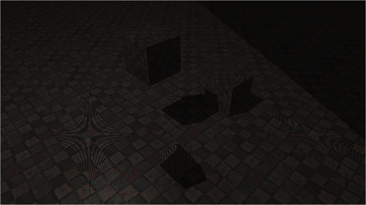
Shadow Acne
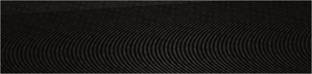
가끔 인터넷에 올라온 사진 줌아웃 하거나, 사진 컴퓨터로 업로드해서 보면
저런 자글자글?한 이상한 효과가 생기는걸 볼 수 있음
저런 무늬를 Moiré라고 부름
그래픽스에서 그림자에 생긴 저런 무늬를 shadow acne라고 부름
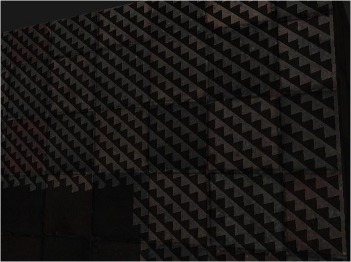
가까이서보면 일정한 무늬가 연속해서 나타나고 있다는걸 알 수 있음
이게 이유가 간단함
우리는 depth map이라는 텍스쳐를 이용해 우리는 그림자를 계산중임
이게 정면으로 빛을 받을때는 문제가 없는데,
빛이 비스듬하게 들어오면 문제가 생김
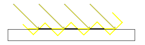
depth map은 3차원 연속적인 공간을 텍셀단위로 저장함
위 그림을 보면 비스듬한 빛이 오게 되면, 텍셀단위로 끊어서 그림자를 계산하므로, 이전 텍셀이 다음 텍셀을 조금이라도 가린다면 그림자가 생기는거임
만약 그림자의 해상도가 굉~~~장히 높다면 문제가 없을수도 있음
하지만 그렇게 되면 연산량도 많아짐
이걸 해결하는건 간단한데, 약간의 offset을 이용하면 됨
float offset = 0.005;
float shadow = currentDepth - offset > closestDepth  ? 1.0 : 0.0;
이렇게 offset을 사용해 해당범위가 포함되면 shadow를 계산하도록 하면 됨
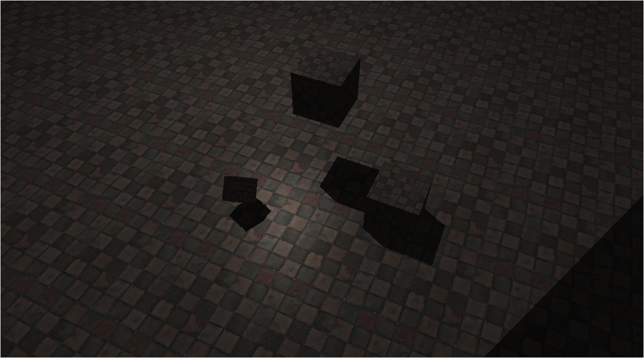
이렇게 shadow acne가 사라진걸 볼 수 있음
다만 이방법도 문제가 있음
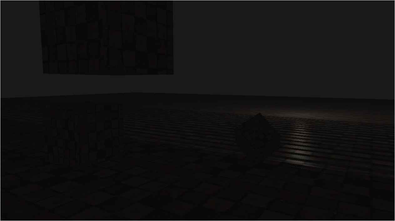
이렇게 빛이 매~~우 비스듬한 각도에서 도착하면 여전히 shadow acne가 생기게 됨
따라서 offset을 계산하는 로직을 수정해야됨
vec3 lightDir = normalize(lightPos - fs_in.FragPos);
float offset = max(0.5 * (1.0 - dot(lightDir, fs_in.Normal)), 0.005);
이렇게 normal과 수직인 각도로 빛이 오면 내적의 결과가 1에 가까워지므로,
0.005라는 최저값을 가지고,
그게 아니라면 적절한 값을 가지도록 함
0.5와 0.005는 특수 offset으로 적절히 shadow acne가 안생기도록 조절하면 됨
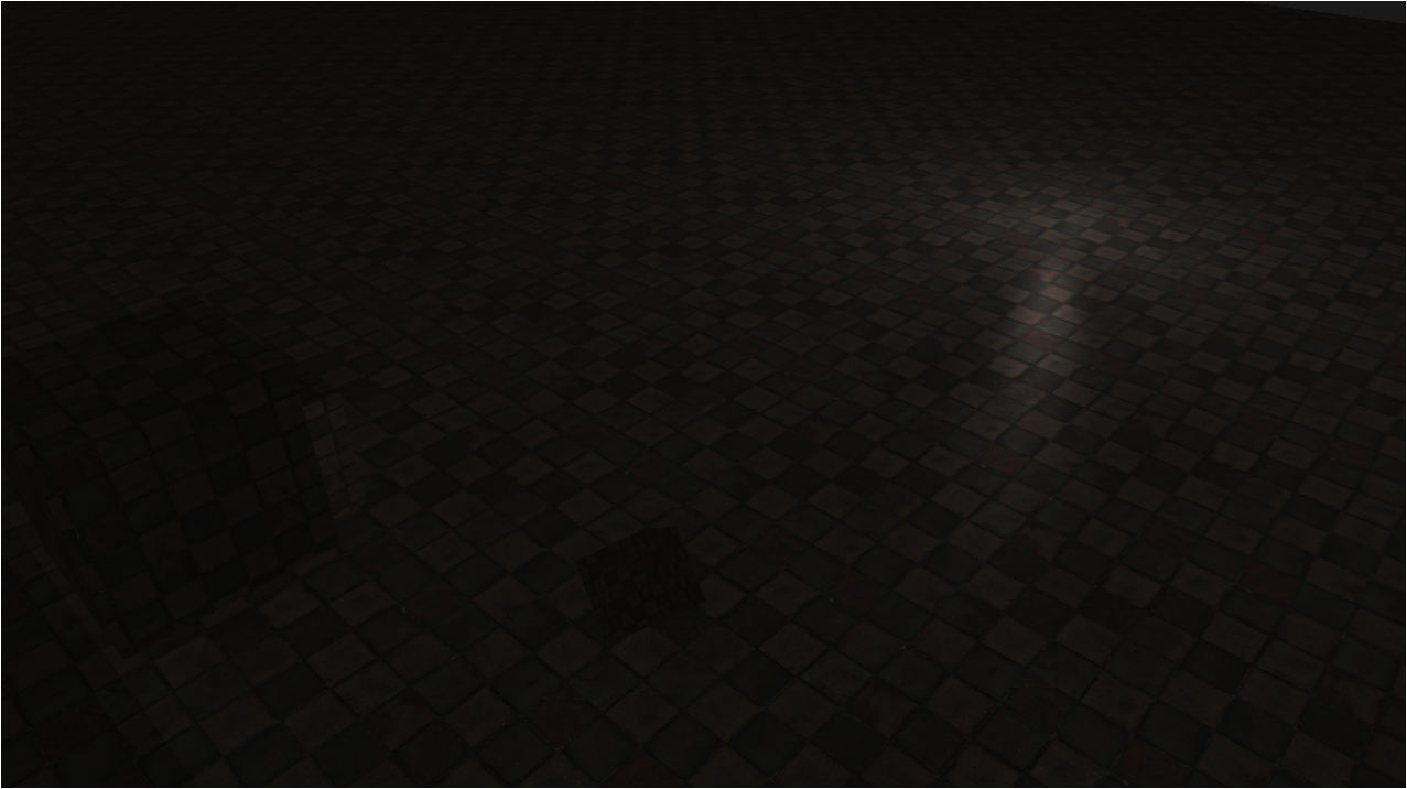
해결완료~~
peter panning
조명과 offset을 잘 조절해보면
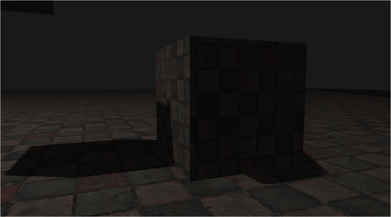
정면의 정육면체는 땅에 붙어있음에도 공중에 뜬것처럼 제대로 그림자가 렌더링되지 않고 있는 모습을 볼 수 잇음
이걸 peter panning이라고 함
이게 생기는 이유는 우리가 위에서 offset을 이용해서 그림자의 위치가 어긋나 보이는거임
해결법은 간단함
depth map을 렌더링하는 동안에 front face culling을 통해 앞면을 없애버리면 됨
기본적으로 OpenGL은 back face culling임
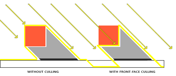
이렇게 적용되도록 꼼수부리는건데
glCullFace(GL_FRONT);
RenderSceneToDepthMap();
glCullFace(GL_BACK); // 원래의 컬링 면으로 되돌리는 것을 잊지 마세요
사실 과도한 bias가 문제라 어떤 방식으로 peter panning을 해결해도 같은 문제가 나타날 수 잇음
따라서 bias를 적절하게 조절하면 됨
over sampling
해결법 1. TextureParameter 수정
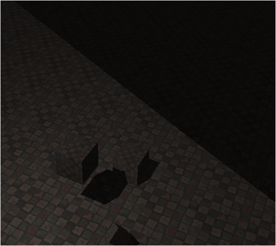
우리는 절두체로 빛이 닿는 곳과 닿지 않는 곳이 구분되고 있음
어두운 부분이 절두체가 끊기는 부분인데,
너무 차이가 심함
glTexParameteri(GL_TEXTURE_2D, GL_TEXTURE_MIN_FILTER, GL_NEAREST);
glTexParameteri(GL_TEXTURE_2D, GL_TEXTURE_MAG_FILTER, GL_NEAREST);
glTexParameteri(GL_TEXTURE_2D, GL_TEXTURE_WRAP_S, GL_REPEAT);
glTexParameteri(GL_TEXTURE_2D, GL_TEXTURE_WRAP_T, GL_REPEAT);
이유는 우리가 GL_REPEAT으로 설정되어있기때문임
만약 텍스쳐좌표가 1.01이면, GL_REPEAT일때 0.01로 매핑되게 됨
그로인해 그림자처럼 어두워지는거임
따라서 우리는 parameter옵션을 0-1사이로 가두는 GL_CLAMP_TO_BORDER를 사용하고
보더의 색상은 흰색으로 하여 기본 fragment색상에 영향이 없도록 설정하면 됨
glTexParameteri(GL_TEXTURE_2D, GL_TEXTURE_MIN_FILTER, GL_NEAREST);
glTexParameteri(GL_TEXTURE_2D, GL_TEXTURE_MAG_FILTER, GL_NEAREST);
glTexParameteri(GL_TEXTURE_2D, GL_TEXTURE_WRAP_S, GL_CLAMP_TO_BORDER);
glTexParameteri(GL_TEXTURE_2D, GL_TEXTURE_WRAP_T, GL_CLAMP_TO_BORDER);
float borderColor[] = {1.0, 1.0, 1.0, 1.0};
glTexParameterfv(GL_TEXTURE_2D, GL_TEXTURE_BORDER_COLOR, borderColor);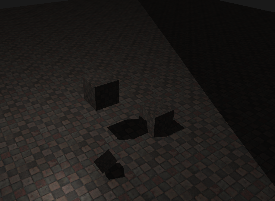
하지만 여전히 문제가 남아있는것을 볼 수 있음
이 방법은 depth map이 0~1사이가 아닐때 적용되는 해결법임
해결법 2. 절두체 밖 z index에 따라 shadow 조절
우리가 정의한 광원공간에서 정점의 z좌표가 음수이거나 1을 초과했다는건
우리가 정의한 near, far절두체 범위 사이에 속하지 않는다는거임
근데 near절두체보다 더 가까이 있는 물체는 이미
projCoords = projCoords * 0.5 + 0.5;라는 정규화과정에서 음수가 되어
float shadow = currentDepth - offset > closestDepth ? 1.0 : 0.0;여기서 무조건 false가 되어 0.0이 되게 됨
따라서 우리는 far절두체 바깥쪽인, projCoords.z가 1을 초과하는 경우에 대해서 shadow계산을 안하도록 하면 됨
if(projCoords.z > 1.0)
	shadow = 0.0;
이런 코드만 추가해주면 됨
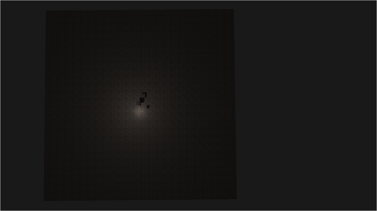
그럼 이렇게 정확한 그림자가 렌더링 되게 됨
PCF
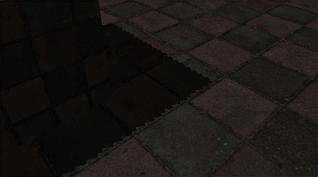
그림자의 해상도가 고정되어 있어서
여러 fragment에 그림자 계산이 더해져 톱니모양이 부각되는 현상이 있음
그럼 AA적용하면 되겠네?
ㅇㅇ그게 바로 PCF, percentage closer filtering이라는 기법임
PCF는 그림자에서만 적용되지 않고,
거칠거나 딱딱한 부분을 뭉그러트리는 기법을 포괄해서 말하는거임
로직은 간단함
//1
float shadow = 0.0;
vec2 texelSize = 1.0 / textureSize(shadowMap, 0);
//2
for(int x = -5; x <= 5; ++x)
{
    for(int y = -5; y <= 5; ++y)
    {
    	//3
        float pcfDepth = texture(shadowMap, projCoords.xy + vec2(x, y) * texelSize).r;
        shadow += currentDepth - bias > pcfDepth ? 1.0 : 0.0;
    }
}
//4
shadow /= 121.0;- textureSize메서드를 이용하면 우리가 사용하는 텍스쳐의 x,y를 알 수 있음
1/textureSize를 통해 텍셀 1개당 간격을 구함 - 텍셀 1개에 대하여 텍셀포함 가로세로 총 121개의 텍셀에 대해 3번을 수행함
- 해당 121개의 텍셀 좌표에 대해 빛을 받으면 0, 아니면 1을 반환
- 121개의 텍셀 좌표의 색상이 합쳐졌으므로 121로 나누어 해당 텍셀의 평균 그림자 세기를 구함
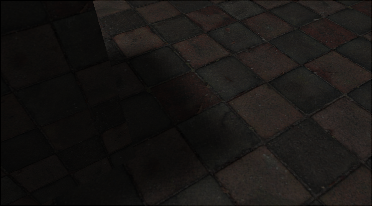
그럼 이렇게 그림자가 뭉개져서 나옴
자세히 보면 약간 각져있긴한데 이정도도 충분한 편이긴함
다시 차이를 보면
| PCF 적용전 | PCF 적용후 |
|---|
PCF는 단순히 이런용도뿐만이 아니긴함
그리고 그림자를 뭉개는것에도 PCF만 있는것도 아님
하지만 그건 매우 고급~~스끼리~
방향광에 대해 직교, 원근 투영의 그림자 차이
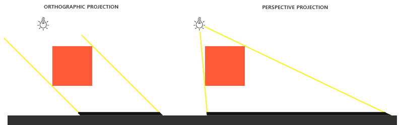
왼쪽이 방향광에서 직교투영, 오른쪽이 방향광에서 원근투영임
딱봐도 오른쪽이 더 깊고 원근감에 의해 그림자가 생긴다는걸 알 수 있음
이로인해 방향광에서는 주로 직교투영을 사용하고
점광, 스포트라이트에서는 원근투영을 주로 사용함
