Advanced OpenGL(12) - Directional Shadow Mapping
여기서 우리는 방향광에 대한 동적 그림자 매핑 기법을 살펴봄
마지막에 원근/직교 투영 그림자 매핑의 차이점을 소개했음
이번에 살펴볼게 바로 원근투영을 이용한 그림자매핑임
이러한 기술을 Omnidirectional Shadow Mapping이라고 함
Omnidirectional shadow mapping
omnidirectional은 omni(모든) + directional(방향)이 합쳐져서
전방향이라는 의미를 가짐
이전챕터에서 살펴본
depth mapFBO를 만들고 렌더링을 통해 depth map텍스쳐를 채운 후
그걸 이용해서 그림자를 만드는것과 비슷함
다만 directional shadow mapping과의 차이점은
사용하게 될 depth map이 다르다는거임
directional shadow mapping에서는 2D공간인 광원공간에서 depth를 체킹해서 그림자가 질 fragment의 색을 빼는식으로 구현했음
하지만 전방향이라는 말에서 알 수 있듯이, 특정 방향만이 아닌 360도 모든 방향에서 빛이 나와 그림자를 체킹해야하므로 일반적인 2D 광원공간에서의 depth map을 생성할수가 없다는거임
그럼 일반적인 2D텍스쳐가 안된다면...우리가 사용할 수 있는 텍스쳐는 뭘까?
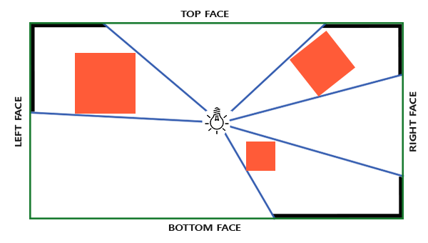
전방향, 즉 상하좌우전후 6개의 면에 그림자를 만드는것과 같은 의미임
따라서 우리는 cubemap을 이용해서 depth map을 만들고, dynamic omnidirectional shadow mapping을 할 수 있게 되는거임ㅇㅇ
따라서 우리는 그림자용 depth map을 cubemap으로 생성하고 텍스쳐를 채운 후
이전챕터에서 다룬 그림자 매핑에 대한 모든걸 그대로 하면 되는거임
Depth Cubemap, 예시
핵심 아이디어
기본적으로 우리가 생각할 수 있는 방법이 있음
6개의 텍스쳐를 각각 생성하고,
해당 텍스쳐를 각각 정점 쉐이더로 보내서 하나씩 계산한다음 합치는 방법임
이 방법이 좋긴한데 몇가지 문제점이 있음
- draw call이 많음
- 6번의 추가적인 렌더링을 해야함
- cpu <-> gpu간의 통신횟수가 잦음
- 결국 광원공간에서 6번 다른방향으로 depth를 계산한다는것과 같으므로, cpu의 광원공간으로 이동시키기 위한 변환행렬을 gpu로 옮겨서 계산을 수행해야함
따라서 우리가 사용할 방법은 geometry shader를 사용하는거임
핵심 아이디어는 아래와 같음
Geometry shader를 통해 gpu에서 한번에 cubemap을 depth map함
- vertex shader에서 변환처리가 끝난 월드(Scene)의 모든 오브젝트의 개별 정점 데이터(삼각형 정점 데이터)가 geometry shader로 넘어옴
- geometry shader에서는 넘어온 오브젝트 각각의 삼각형 정점(
gs_in[0],gs_in[1],gs_in[2])들을 각각 6번 복제- 반복문을 통해 각 면을 선택하고, 해당 면에 알맞은 변환행렬을 정점에 곱해 광원공간으로 이동시킴
- 광원공간으로 이동된 정점을
EmitVertex를 통해 적용 - 면마다 반복
예시
1. cubemap 생성
uint32_t depthCubemap;
glGenTextures(1, &depthCubemap);
const unsigned int SHADOW_WIDTH = 1024, SHADOW_HEIGHT = 1024;
glBindTexture(GL_TEXTURE_CUBE_MAP, depthCubemap);
for (unsigned int i = 0; i < 6; ++i)
{
    glTexImage2D(GL_TEXTURE_CUBE_MAP_POSITIVE_X + i, 0, GL_DEPTH_COMPONENT, SHADOW_WIDTH, SHADOW_HEIGHT, 0, GL_DEPTH_COMPONENT, GL_FLOAT, NULL);
}
glTexParameteri(GL_TEXTURE_CUBE_MAP, GL_TEXTURE_MAG_FILTER, GL_NEAREST);
glTexParameteri(GL_TEXTURE_CUBE_MAP, GL_TEXTURE_MIN_FILTER, GL_NEAREST);
glTexParameteri(GL_TEXTURE_CUBE_MAP, GL_TEXTURE_WRAP_S, GL_CLAMP_TO_EDGE);
glTexParameteri(GL_TEXTURE_CUBE_MAP, GL_TEXTURE_WRAP_T, GL_CLAMP_TO_EDGE);
glTexParameteri(GL_TEXTURE_CUBE_MAP, GL_TEXTURE_WRAP_R, GL_CLAMP_TO_EDGE);
glBindFramebuffer(GL_FRAMEBUFFER, depthMapFBO);
glFramebufferTexture(GL_FRAMEBUFFER, GL_DEPTH_ATTACHMENT, depthCubemap, 0);
glDrawBuffer(GL_NONE);
glReadBuffer(GL_NONE);
glBindFramebuffer(GL_FRAMEBUFFER, 0);
depthCubemap을 생성함
cubemap의 각면에 대해 그림자 해상도를 이용해서 값 설정
texture parameter는 cubemap이므로 각 면이 끝나는 지점에서 끊기지 않게 GL_CLAMP_TO_EDGE사용
2. 렌더
// 1. first render to depth cubemap
glViewport(0, 0, SHADOW_WIDTH, SHADOW_HEIGHT);
glBindFramebuffer(GL_FRAMEBUFFER, depthMapFBO);
    glClear(GL_DEPTH_BUFFER_BIT);
    ConfigureShaderAndMatrices();
    RenderScene();
glBindFramebuffer(GL_FRAMEBUFFER, 0);

// 2. then render scene as normal with shadow mapping (using depth cubemap)
glViewport(0, 0, SCR_WIDTH, SCR_HEIGHT);
glClear(GL_COLOR_BUFFER_BIT | GL_DEPTH_BUFFER_BIT);
ConfigureShaderAndMatrices();
glBindTexture(GL_TEXTURE_CUBE_MAP, depthCubemap);
RenderScene();
directional shadow mapping과 마찬가지로 먼저 depth map을 렌더링을 통해 매핑시키고, 화면에 출력
3. 광원공간 변환행렬
directional과는 다르게 6면이므로, 각 면에 대해서 변환행렬을 만들어줘야함
그리고 직교투영이 아닌 원근투영으로 그림자가 올바르게 mapping되도록 할거임
//1
float aspect = (float)SHADOW_WIDTH/(float)SHADOW_HEIGHT;
float near = 1.0f;
float far = 25.0f;
glm::mat4 shadowProj = glm::perspective(glm::radians(90.0f), aspect, near, far);

//2
std::vector<glm::mat4> shadowTransforms;
shadowTransforms.push_back(shadowProj * glm::lookAt(lightPos, lightPos + glm::vec3( 1.0, 0.0, 0.0), glm::vec3(0.0,-1.0, 0.0));
shadowTransforms.push_back(shadowProj * glm::lookAt(lightPos, lightPos + glm::vec3(-1.0, 0.0, 0.0), glm::vec3(0.0,-1.0, 0.0));
shadowTransforms.push_back(shadowProj * glm::lookAt(lightPos, lightPos + glm::vec3( 0.0, 1.0, 0.0), glm::vec3(0.0, 0.0, 1.0));
shadowTransforms.push_back(shadowProj * glm::lookAt(lightPos, lightPos + glm::vec3( 0.0,-1.0, 0.0), glm::vec3(0.0, 0.0,-1.0));
shadowTransforms.push_back(shadowProj * glm::lookAt(lightPos, lightPos + glm::vec3( 0.0, 0.0, 1.0), glm::vec3(0.0,-1.0, 0.0));
shadowTransforms.push_back(shadowProj * glm::lookAt(lightPos, lightPos + glm::vec3( 0.0, 0.0,-1.0), glm::vec3(0.0,-1.0, 0.0));- 그림자 해상도의 비율, near/far절두체를 이용해서
시야각이 90도인 그림자 해상도 비율을 가지는 near/far절두체를 사용하는 원근투영행렬을 만들음- 시야각이 90도일때, 한면을 가득 채우는 범위를 가짐
- 광원공간으로 이동시키는 변환행렬 6개를 cubemap의 각 방향에 맞게 설정
- lookAt메서드는 eye(위치), center(중앙방향), up(위방향)을 넣어줘야함
- lightPos에서 바라보고, light pos기준 x,-x,y,-y,z,-z방향의 cubemap center방향을 선택
- 세번째 파라미터가 중요한데, cubemap이라는건 텍스쳐를 의미함
하지만 opengl의 좌표를 이용해서 오른손 좌표계를 통해 x = 0, x = -1, z = 0, z = -1일때의 up방향을 (0,1,0)으로 해버리면, 텍스쳐 좌표에서의 up인 (0,-1,0)과 반대방향이기때문에 뒤집혀버림
따라서 (0,-1,0)으로 y축의 up방향을 만들어줘야함
4. depth map용 shaders
여기까지 했으면 vertex, fragment, geometry 3개의 쉐이더를 정의해줘야함
geometry가 당연히 중요하긋지?
vertex shader
이제 쉐이더들을 정의해야함
directional과 다르게 vertex에서는 단순하게 월드공간으로 정점을 변환시켜주기만 하면 됨
#version 330 core
layout (location = 0) in vec3 aPos;
uniform mat4 model;
void main()
{
    gl_Position = model * vec4(aPos, 1.0);
}
geometry shader
#version 330 core
layout (triangles) in;
layout (triangle_strip, max_vertices=18) out;
uniform mat4 shadowMatrices[6];
out vec4 FragPos; // FragPos from GS (output per emitvertex)

void main()
{
    for(int face = 0; face < 6; ++face)
    {
        gl_Layer = face; // built-in variable that specifies to which face we render.
        for(int i = 0; i < 3; ++i) // for each triangle vertex
        {
            FragPos = gl_in[i].gl_Position;
            gl_Position = shadowMatrices[face] * FragPos;
            EmitVertex();
        }
        EndPrimitive();
    }
}- 입력을 우리가 그릴 삼각형으로 받음
- 큐브맵 6개의 면에 입력으로 받는 삼각형을 렌더링할것이므로 최대 정점 18개로 그림
- 각면에 대해
gl_Layer를 반복문을 통해 face로 바꿔주면서 0~5의 큐브맵에 삼각형이 렌더링 되도록 함 - 이제 입력된 삼각형 정점을 광원공간으로 변환하고 정점을 Emit후, 해당 cubemap면에 적용시킴
어렵지 않지?
핵심은 gl_Layer임!
fragment shader
directional처럼 아무것도 안넘겨도 괜찮은걸까 싶지만
그렇지 않음
일단 directional은 직교투영이기 때문에 따로 뭐 해줄필요가 없이 자동으로 gl_FragCoords를 이용해 gl_FragDepth 값이 업데이트 되었는데
우리는 원근투영을 사용함
그리고 원근투영에서는 w가중치를 이용해 비선형적으로 depth를 체킹함
비선형적?
ㅤ
카메라와 가까울때 더 높은 정밀도로 z index를 계산하고, 카메라와 멀어질수록 z index의 정밀도가 낮아지는걸 비선형적이라고 함
하지만 비선형적이라는 말은
광원에서 물체까지의 정확한 거리(z index)가 아니게 됨
이게 무슨뜻이고?
ㅤ
예를들어 광원에서부터 거리가 5만큼 떨어진 물체가 있다고 해보자
비선형적 z index와 선형적 z index는 다름
따라서 우리는 비선형적으로 계산한 z index가 아닌
직접 선형적으로 z index를 계산해서 depth값으로 넣어줘야함
그리고 이건 어렵지 않음
#version 330 core
in vec4 FragPos;
uniform vec3 lightPos;
uniform float far_plane;

void main()
{
    // get distance between fragment and light source
    float lightDistance = length(FragPos.xyz - lightPos);

    // map to [0;1] range by dividing by far_plane
    lightDistance = lightDistance / far_plane;

    // write this as modified depth
    gl_FragDepth = lightDistance;
}- Fragment좌표에서 광원좌표까지의 거리를 구함
- 0~1사이로 값을 정하고 일정한 간격을 가지도록 하기 위해
광원좌표까지의 거리 / far절두체를 해서 선형적으로 0~1사이의 값을 가지도록 정규화함 - 이 값을 Depth로 사용해줌
간단하지?
5. shadow shader
렌더링 준비물
// renders the 3D scene
// --------------------
void renderScene(const Shader &shader)
{
    // room cube
    glm::mat4 model = glm::mat4(1.0f);
    model = glm::scale(model, glm::vec3(10.0f));
    shader.setMat4("model", model);
    glDisable(GL_CULL_FACE); //큐브 안쪽에서 확인할거라, 큐브의 밖이 아닌 안쪽이 렌더링 되어야함
    shader.setInt("reverse_normals", 1); //안쪽이 렌더링된다는걸 의미
    renderCube(); //여러 큐브를 감쌀 큰 큐브 1개만 만들기
    shader.setInt("reverse_normals", 0); //큰 큐브 만들었으면 다시 바깥쪽 렌더링으로 바꾸기
    glEnable(GL_CULL_FACE);//큰 큐브 만들었으면 다시 바깥쪽 렌더링으로 바꾸기
    // cubes
    model = glm::mat4(1.0f);
    model = glm::translate(model, glm::vec3(4.0f, -3.5f, 0.0));
    model = glm::scale(model, glm::vec3(0.5f));
    shader.setMat4("model", model);
    renderCube();
    model = glm::mat4(1.0f);
    model = glm::translate(model, glm::vec3(2.0f, 3.0f, 1.0));
    model = glm::scale(model, glm::vec3(0.75f));
    shader.setMat4("model", model);
    renderCube();
    model = glm::mat4(1.0f);
    model = glm::translate(model, glm::vec3(-3.0f, -1.0f, 0.0));
    model = glm::scale(model, glm::vec3(0.5f));
    shader.setMat4("model", model);
    renderCube();
    model = glm::mat4(1.0f);
    model = glm::translate(model, glm::vec3(-1.5f, 1.0f, 1.5));
    model = glm::scale(model, glm::vec3(0.5f));
    shader.setMat4("model", model);
    renderCube();
    model = glm::mat4(1.0f);
    model = glm::translate(model, glm::vec3(-1.5f, 2.0f, -3.0));
    model = glm::rotate(model, glm::radians(60.0f), glm::normalize(glm::vec3(1.0, 0.0, 1.0)));
    model = glm::scale(model, glm::vec3(0.75f));
    shader.setMat4("model", model);
    renderCube();
}

// renderCube() renders a 1x1 3D cube in NDC.
// -------------------------------------------------
unsigned int cubeVAO = 0;
unsigned int cubeVBO = 0;
void renderCube()
{
    // initialize (if necessary)
    if (cubeVAO == 0)
    {
        float vertices[] = {
            // back face
            -1.0f, -1.0f, -1.0f,  0.0f,  0.0f, -1.0f, 0.0f, 0.0f, // bottom-left
             1.0f,  1.0f, -1.0f,  0.0f,  0.0f, -1.0f, 1.0f, 1.0f, // top-right
             1.0f, -1.0f, -1.0f,  0.0f,  0.0f, -1.0f, 1.0f, 0.0f, // bottom-right
             1.0f,  1.0f, -1.0f,  0.0f,  0.0f, -1.0f, 1.0f, 1.0f, // top-right
            -1.0f, -1.0f, -1.0f,  0.0f,  0.0f, -1.0f, 0.0f, 0.0f, // bottom-left
            -1.0f,  1.0f, -1.0f,  0.0f,  0.0f, -1.0f, 0.0f, 1.0f, // top-left
            // front face
            -1.0f, -1.0f,  1.0f,  0.0f,  0.0f,  1.0f, 0.0f, 0.0f, // bottom-left
             1.0f, -1.0f,  1.0f,  0.0f,  0.0f,  1.0f, 1.0f, 0.0f, // bottom-right
             1.0f,  1.0f,  1.0f,  0.0f,  0.0f,  1.0f, 1.0f, 1.0f, // top-right
             1.0f,  1.0f,  1.0f,  0.0f,  0.0f,  1.0f, 1.0f, 1.0f, // top-right
            -1.0f,  1.0f,  1.0f,  0.0f,  0.0f,  1.0f, 0.0f, 1.0f, // top-left
            -1.0f, -1.0f,  1.0f,  0.0f,  0.0f,  1.0f, 0.0f, 0.0f, // bottom-left
            // left face
            -1.0f,  1.0f,  1.0f, -1.0f,  0.0f,  0.0f, 1.0f, 0.0f, // top-right
            -1.0f,  1.0f, -1.0f, -1.0f,  0.0f,  0.0f, 1.0f, 1.0f, // top-left
            -1.0f, -1.0f, -1.0f, -1.0f,  0.0f,  0.0f, 0.0f, 1.0f, // bottom-left
            -1.0f, -1.0f, -1.0f, -1.0f,  0.0f,  0.0f, 0.0f, 1.0f, // bottom-left
            -1.0f, -1.0f,  1.0f, -1.0f,  0.0f,  0.0f, 0.0f, 0.0f, // bottom-right
            -1.0f,  1.0f,  1.0f, -1.0f,  0.0f,  0.0f, 1.0f, 0.0f, // top-right
            // right face
             1.0f,  1.0f,  1.0f,  1.0f,  0.0f,  0.0f, 1.0f, 0.0f, // top-left
             1.0f, -1.0f, -1.0f,  1.0f,  0.0f,  0.0f, 0.0f, 1.0f, // bottom-right
             1.0f,  1.0f, -1.0f,  1.0f,  0.0f,  0.0f, 1.0f, 1.0f, // top-right
             1.0f, -1.0f, -1.0f,  1.0f,  0.0f,  0.0f, 0.0f, 1.0f, // bottom-right
             1.0f,  1.0f,  1.0f,  1.0f,  0.0f,  0.0f, 1.0f, 0.0f, // top-left
             1.0f, -1.0f,  1.0f,  1.0f,  0.0f,  0.0f, 0.0f, 0.0f, // bottom-left
            // bottom face
            -1.0f, -1.0f, -1.0f,  0.0f, -1.0f,  0.0f, 0.0f, 1.0f, // top-right
             1.0f, -1.0f, -1.0f,  0.0f, -1.0f,  0.0f, 1.0f, 1.0f, // top-left
             1.0f, -1.0f,  1.0f,  0.0f, -1.0f,  0.0f, 1.0f, 0.0f, // bottom-left
             1.0f, -1.0f,  1.0f,  0.0f, -1.0f,  0.0f, 1.0f, 0.0f, // bottom-left
            -1.0f, -1.0f,  1.0f,  0.0f, -1.0f,  0.0f, 0.0f, 0.0f, // bottom-right
            -1.0f, -1.0f, -1.0f,  0.0f, -1.0f,  0.0f, 0.0f, 1.0f, // top-right
            // top face
            -1.0f,  1.0f, -1.0f,  0.0f,  1.0f,  0.0f, 0.0f, 1.0f, // top-left
             1.0f,  1.0f , 1.0f,  0.0f,  1.0f,  0.0f, 1.0f, 0.0f, // bottom-right
             1.0f,  1.0f, -1.0f,  0.0f,  1.0f,  0.0f, 1.0f, 1.0f, // top-right
             1.0f,  1.0f,  1.0f,  0.0f,  1.0f,  0.0f, 1.0f, 0.0f, // bottom-right
            -1.0f,  1.0f, -1.0f,  0.0f,  1.0f,  0.0f, 0.0f, 1.0f, // top-left
            -1.0f,  1.0f,  1.0f,  0.0f,  1.0f,  0.0f, 0.0f, 0.0f  // bottom-left
        };
        glGenVertexArrays(1, &cubeVAO);
        glGenBuffers(1, &cubeVBO);
        // fill buffer
        glBindBuffer(GL_ARRAY_BUFFER, cubeVBO);
        glBufferData(GL_ARRAY_BUFFER, sizeof(vertices), vertices, GL_STATIC_DRAW);
        // link vertex attributes
        glBindVertexArray(cubeVAO);
        glEnableVertexAttribArray(0);
        glVertexAttribPointer(0, 3, GL_FLOAT, GL_FALSE, 8 * sizeof(float), (void*)0);
        glEnableVertexAttribArray(1);
        glVertexAttribPointer(1, 3, GL_FLOAT, GL_FALSE, 8 * sizeof(float), (void*)(3 * sizeof(float)));
        glEnableVertexAttribArray(2);
        glVertexAttribPointer(2, 2, GL_FLOAT, GL_FALSE, 8 * sizeof(float), (void*)(6 * sizeof(float)));
        glBindBuffer(GL_ARRAY_BUFFER, 0);
        glBindVertexArray(0);
    }
    // render Cube
    glBindVertexArray(cubeVAO);
    glDrawArrays(GL_TRIANGLES, 0, 36);
    glBindVertexArray(0);
}
이런 두 렌더링용 메서드가 있음
scene을 렌더링할때 사용하게 될거임
render scene메서드에서 가장 최상단 큐브 1개를 먼저 만들때가 중요
우리는 omnidirectional 그림자가 제대로 매핑되는지 확인하기 위해 방 전체를 큐브로 감쌀거임
따라서 가장 큰 큐브, 우리가 들어가서 확인할 큐브는,,,,
바깥쪽에서 렌더링되는게 아닌 안쪽에서 렌더링 되어야함
따라서 culling face잠시 disable해서 카메라에서 보이지 않는 면에 있더라도 렌더링하도록 바꾸고,
큰 큐브를 그린다음,
culling face를 enable해서 안보이는 면은 렌더링 되지 않도록 바꿈
vertex shader
정점들을 받아서 스크린 좌표로 이동시켜주면 됨
#version 330 core
layout (location = 0) in vec3 aPos;
layout (location = 1) in vec3 aNormal;
layout (location = 2) in vec2 aTexCoords;

out vec2 TexCoords;

out VS_OUT {
    vec3 FragPos;
    vec3 Normal;
    vec2 TexCoords;
} vs_out;

uniform mat4 projection;
uniform mat4 view;
uniform mat4 model;

uniform bool reverse_normals;

void main()
{
    vs_out.FragPos = vec3(model * vec4(aPos, 1.0));
    if (reverse_normals) // a slight hack to make sure the outer large cube displays lighting from the 'inside' instead of the default 'outside'.
    {
        vs_out.Normal = transpose(inverse(mat3(model))) * (-1.0 * aNormal);
    }
    else
    {
        vs_out.Normal = transpose(inverse(mat3(model))) * aNormal;
    }

    vs_out.TexCoords = aTexCoords;
    gl_Position = projection * view * model * vec4(aPos, 1.0);
}
여기서 눈여겨 봐야할건 normal을 뒤집는거임
위에서 reverse normal을 넘겨서 normal을 뒤집음
normal을 뒤집는 이유는 빛 계산과 관련이 있음
큰 큐브에서 normal이 그대로라면
ㅤ
vec3 lightDir = normalize(lightPos - fs_in.FragPos);의 계산결과인 pixel->light로 향하는 방향과 정반대이므로
빛계산시에 dot product를 하면 그림자가 진것처럼 표현되게 됨
fragment shader
#version 330 core
out vec4 FragColor;

in VS_OUT {
    vec3 FragPos;
    vec3 Normal;
    vec2 TexCoords;
} fs_in;

uniform sampler2D diffuseTexture;
uniform samplerCube depthMap;

uniform vec3 lightPos;
uniform vec3 viewPos;

uniform float far_plane;

float ShadowCalculation(vec3 fragPos)
{
    // get vector between fragment position and light position
    vec3 fragToLight = fragPos - lightPos;
    // ise the fragment to light vector to sample from the depth map
    float closestDepth = texture(depthMap, fragToLight).r;
    // it is currently in linear range between [0,1], let's re-transform it back to original depth value
    closestDepth *= far_plane;
    // now get current linear depth as the length between the fragment and light position
    float currentDepth = length(fragToLight);
    // test for shadows
    float bias = 0.05; // we use a much larger bias since depth is now in [near_plane, far_plane] range
    float shadow = currentDepth -  bias > closestDepth ? 1.0 : 0.0;
    // display closestDepth as debug (to visualize depth cubemap)
    // FragColor = vec4(vec3(closestDepth / far_plane), 1.0);

    return shadow;
}

void main()
{
    vec3 color = texture(diffuseTexture, fs_in.TexCoords).rgb;
    vec3 normal = normalize(fs_in.Normal);
    vec3 lightColor = vec3(0.3);
    // ambient
    vec3 ambient = 0.3 * lightColor;
    // diffuse
    vec3 lightDir = normalize(lightPos - fs_in.FragPos);
    float diff = max(dot(lightDir, normal), 0.0);
    vec3 diffuse = diff * lightColor;
    // specular
    vec3 viewDir = normalize(viewPos - fs_in.FragPos);
    float spec = 0.0;
    vec3 halfwayDir = normalize(lightDir + viewDir);
    spec = pow(max(dot(normal, halfwayDir), 0.0), 64.0);
    vec3 specular = spec * lightColor;
    // calculate shadow
    float shadow = ShadowCalculation(fs_in.FragPos) ;
    vec3 lighting = (ambient + (1.0 - shadow) * (diffuse + specular)) * color;

    FragColor = vec4(lighting, 1.0);
}
하나씩 천천히 보자
ShadowCalculation메서드
float ShadowCalculation(vec3 fragPos)
{
    // get vector between fragment position and light position
    vec3 fragToLight = fragPos - lightPos;
    // ise the fragment to light vector to sample from the depth map
    float closestDepth = texture(depthMap, fragToLight).r;
    // it is currently in linear range between [0,1], let's re-transform it back to original depth value
    closestDepth *= far_plane;
    // now get current linear depth as the length between the fragment and light position
    float currentDepth = length(fragToLight);
    // test for shadows
    float bias = 0.05; // we use a much larger bias since depth is now in [near_plane, far_plane] range
    float shadow = currentDepth -  bias > closestDepth ? 1.0 : 0.0;
    // display closestDepth as debug (to visualize depth cubemap)
    // FragColor = vec4(vec3(closestDepth / far_plane), 1.0);

    return shadow;
}- 먼저 light에서 fragment로 향하는 방향벡터를 구함
- depth map에서 해당 방향벡터의 좌표에 해당되는 값을 가져옴
- 가져온 depth는 0~1로 정규화되어 잇는 값이므로, far_plane을 곱해 실제 depth로 바꿔줌
- 현재 fragment의 depth는 1번에서 구한 방향벡터의 길이임
- acne를 방지하기위해 약간의 bias(offset)을 주고, 조건에 맞춰 1혹은 0을 넘김
크게 어렵지 않은 코드임 이건ㅇㅇ
main메서드
void main()
{
    vec3 color = texture(diffuseTexture, fs_in.TexCoords).rgb;
    vec3 normal = normalize(fs_in.Normal);
    vec3 lightColor = vec3(0.3);
    // ambient
    vec3 ambient = 0.3 * lightColor;
    // diffuse
    vec3 lightDir = normalize(lightPos - fs_in.FragPos);
    float diff = max(dot(lightDir, normal), 0.0);
    vec3 diffuse = diff * lightColor;
    // specular
    vec3 viewDir = normalize(viewPos - fs_in.FragPos);
    float spec = 0.0;
    vec3 halfwayDir = normalize(lightDir + viewDir);
    spec = pow(max(dot(normal, halfwayDir), 0.0), 64.0);
    vec3 specular = spec * lightColor;
    // calculate shadow
    float shadow = ShadowCalculation(fs_in.FragPos) ;
    vec3 lighting = (ambient + (1.0 - shadow) * (diffuse + specular)) * color;

    FragColor = vec4(lighting, 1.0);
}
그냥 blinn phong임ㅇㅇ
6. 렌더링
while (!glfwWindowShouldClose(window))
{
//...
// move light position over time
lightPos.z = static_cast<float>(sin(glfwGetTime() * 0.5) * 3.0);
// render
// ------
glClearColor(0.1f, 0.1f, 0.1f, 1.0f);
glClear(GL_COLOR_BUFFER_BIT | GL_DEPTH_BUFFER_BIT);
// 0. create depth cubemap transformation matrices
// -----------------------------------------------
float near_plane = 1.0f;
float far_plane = 25.0f;
glm::mat4 shadowProj = glm::perspective(glm::radians(90.0f), (float)SHADOW_WIDTH / (float)SHADOW_HEIGHT, near_plane, far_plane);
std::vector<glm::mat4> shadowTransforms;
shadowTransforms.push_back(shadowProj * glm::lookAt(lightPos, lightPos + glm::vec3( 1.0f, 0.0f, 0.0f), glm::vec3(0.0f, -1.0f, 0.0f)));
shadowTransforms.push_back(shadowProj * glm::lookAt(lightPos, lightPos + glm::vec3(-1.0f, 0.0f, 0.0f), glm::vec3(0.0f, -1.0f, 0.0f)));
shadowTransforms.push_back(shadowProj * glm::lookAt(lightPos, lightPos + glm::vec3( 0.0f, 1.0f, 0.0f), glm::vec3(0.0f, 0.0f, 1.0f)));
shadowTransforms.push_back(shadowProj * glm::lookAt(lightPos, lightPos + glm::vec3( 0.0f, -1.0f, 0.0f), glm::vec3(0.0f, 0.0f, -1.0f)));
shadowTransforms.push_back(shadowProj * glm::lookAt(lightPos, lightPos + glm::vec3( 0.0f, 0.0f, 1.0f), glm::vec3(0.0f, -1.0f, 0.0f)));
shadowTransforms.push_back(shadowProj * glm::lookAt(lightPos, lightPos + glm::vec3( 0.0f, 0.0f, -1.0f), glm::vec3(0.0f, -1.0f, 0.0f)));
// 1. render scene to depth cubemap
// --------------------------------
glViewport(0, 0, SHADOW_WIDTH, SHADOW_HEIGHT);
glBindFramebuffer(GL_FRAMEBUFFER, depthMapFBO);
glClear(GL_DEPTH_BUFFER_BIT);
simpleDepthShader.use();
for (unsigned int i = 0; i < 6; ++i)
simpleDepthShader.setMat4("shadowMatrices[" + std::to_string(i) + "]", shadowTransforms[i]);
simpleDepthShader.setFloat("far_plane", far_plane);
simpleDepthShader.setVec3("lightPos", lightPos);
renderScene(simpleDepthShader);
glBindFramebuffer(GL_FRAMEBUFFER, 0);
// 2. render scene as normal
// -------------------------
glViewport(0, 0, SCR_WIDTH, SCR_HEIGHT);
glClear(GL_COLOR_BUFFER_BIT | GL_DEPTH_BUFFER_BIT);
shader.use();
glm::mat4 projection = glm::perspective(glm::radians(camera.Zoom), (float)SCR_WIDTH / (float)SCR_HEIGHT, 0.1f, 100.0f);
glm::mat4 view = camera.GetViewMatrix();
shader.setMat4("projection", projection);
shader.setMat4("view", view);
// set lighting uniforms
shader.setVec3("lightPos", lightPos);
shader.setVec3("viewPos", camera.Position);
shader.setFloat("far_plane", far_plane);
glActiveTexture(GL_TEXTURE0);
glBi
ndTexture(GL_TEXTURE_2D, woodTexture);
glActiveTexture(GL_TEXTURE1);
glBindTexture(GL_TEXTURE_CUBE_MAP, depthCubemap);
renderScene(shader);
//...
}천천히 보면
다 알만한 내용들임
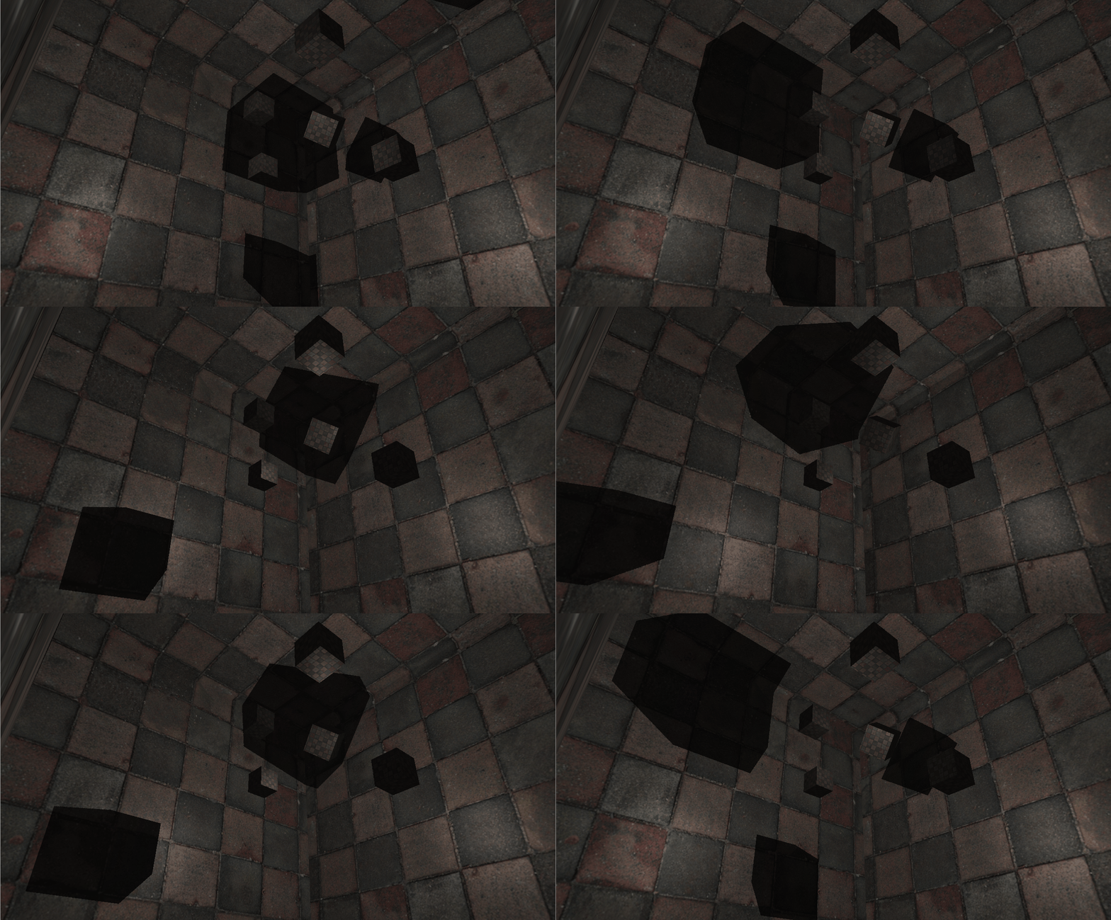
그럼 결과는,.....?
PCF
한번 여기에서도 PCF를 적용해보자
//1
float shadow  = 0.0;
float bias    = 0.05;
float samples = 4.0;
float offset  = 0.1;

//2
for(float x = -offset; x < offset; x += offset / (samples * 0.5))
{
    for(float y = -offset; y < offset; y += offset / (samples * 0.5))
    {
        for(float z = -offset; z < offset; z += offset / (samples * 0.5))
        {
            float closestDepth = texture(depthMap, fragToLight + vec3(x, y, z)).r;
            closestDepth *= far_plane;
            if(currentDepth - bias > closestDepth)
                shadow += 1.0;
        }
    }
}

//3
shadow /= (samples * samples * samples);
3차원이므로 x,y,z방향으로 그림자 샘플링 할거임
- samples수만큼의 가로,높이,깊이를 샘플링함
- -offset~offset까지 샘플수만큼 샘플링하면서 계산
light에서 fragment방향인 벡터에 3차원 샘플좌표의 depth를 구함
조건에 따라서 shadow에 1을 더함 - 최대 샘플수는 가로 * 높이 * 깊이 이므로 64를 1씩 더한 shadow에서 나눠줌
PCF개선
현재 64개의 샘플을 샘플링중임
프레임 한번에 최소 64번의 계산이 필요하다는거니까...
따라서 샘플링 횟수를 조금 줄이는게 좋음
그렇다고 샘플이 2개면 여전히 텍셀단위로 그림자가 출력됨ㅇㅇㅇ
즉, 샘플수를 줄이면서 PCF는 유지되도록 해야함
사실 우리는 한 정점에서 x,y,z축으로 각각 -1, 0, 1의 방향에 있는 면과 공간에 대해서 PCF를 적용하면 됨
따라서 3개의 축에 3가지 경우의 수니 개 방향으로만 샘플링하면 됨!
은 무슨!!!!!!!
ㅤ
일단 1개는 확실히 빠져야함
0벡터 ㅇㅇ
ㅤ
fragToLight + 0벡터 = fragToLight임
근데 자기자신을 샘플링에 포함시키면 가중치가 자기자신 픽셀이 쏠리게 됨
ㅤ
그리고 추가로 빠져야할 벡터들이 있음
?바로 축방향임
(0,0,1), (0,0,-1), (0,1,0)...이런 방향임
이런 축방향을 추가하면 여러 픽셀에서 해당 축방향으로 그림자가 계속 중첩됨
즉, 더 높은 밀도를 가지게 된다는거임ㅤ잘생각해보면 인접한 2개의 픽셀이 특정 축방향벡터에 그림자 계산을 하게되면, 인접한 2개의 픽셀의 그림자가 뚜렷해지게 보이게 될거임ㅇㅇ
따라서 이런 축방향도 없애줘야함
사실 위 인용문구처럼 0벡터, 축방향벡터를 없앤다는게 기하학적 의미가 있음
특정 픽셀에서 모든 모서리와 모든 edge(변)에만 샘플링에 추가된다는거임
즉, 모든 위치에서 동일하게 샘플링 할 수 있다는 의미임
그 벡터들의 집합은 아래와 같음
vec3 sampleOffsetDirections[20] = vec3[]
(
   vec3( 1,  1,  1), vec3( 1, -1,  1), vec3(-1, -1,  1), vec3(-1,  1,  1),
   vec3( 1,  1, -1), vec3( 1, -1, -1), vec3(-1, -1, -1), vec3(-1,  1, -1),
   vec3( 1,  1,  0), vec3( 1, -1,  0), vec3(-1, -1,  0), vec3(-1,  1,  0),
   vec3( 1,  0,  1), vec3(-1,  0,  1), vec3( 1,  0, -1), vec3(-1,  0, -1),
   vec3( 0,  1,  1), vec3( 0, -1,  1), vec3( 0, -1, -1), vec3( 0,  1, -1)
);
따라서 우린 이걸로 샘플링을 하면됨
귀찮게 offset, sample, 반복문사용하지 말구 ㅇㅇ
float shadow = 0.0;
float bias   = 0.15;
int samples  = 20;
float diskRadius = 0.05;
//float viewDistance = length(viewPos - fragPos);
//float diskRadius = (1.0 + (viewDistance / far_plane)) / 25.0;
for(int i = 0; i < samples; ++i)
{
    float closestDepth = texture(depthMap, fragToLight + sampleOffsetDirections[i] * diskRadius).r;
    closestDepth *= far_plane;   // 0~1 매핑 복구
    if(currentDepth - bias > closestDepth)
        shadow += 1.0;
}
shadow /= float(samples);

// display closestDepth as debug (to visualize depth cubemap)
// FragColor = vec4(vec3(closestDepth / far_plane), 1.0);

return shadow;
중요한 부분은 float closestDepth = texture(depthMap, fragToLight + sampleOffsetDirections[i] * diskRadius).r;임
diskRadius를 어떻게 잡느냐에 따라 그림자의 흐릿함정도가 커지거나 줄어들음
만약 diskRadius가 1이라면...
우리가 설정한 모든 샘플방향 크기만큼 샘플링이 되므로 흐릿함이 엄청 커질거고
만약 diskRadius가 0이라면...
우리가 설정한 모든 샘플방향이 무시되므로, 텍셀이 그대로 보이게 될거임ㅇㅇ
float viewDistance = length(viewPos - fragPos);
float diskRadius = (1.0 + (viewDistance / far_plane)) / 25.0;
이건 비선형적으로 diskRadius를 변화시킨거임
가까운 거리일수록 높은 정밀도의 그림자를 가지고,
먼 거리일수록 낮은 정밀도의 그림자를 가지도록 하는거임ㅇㅇ
잘 적용되었다~~~
