forward & inverse kinematics는 로보틱스에서 필수적인 전공 지식이다.
다관절 로봇에서 원하는 동작을 구현할 때, 위치를 기반으로 코드를 작성하는 편이 훨씬 쉽고 정교한 모션을 뽑을 수 있다.
계산이 길 뿐, 원리 자체는 단순하다.
1. 2링크의 Forward Kinematics
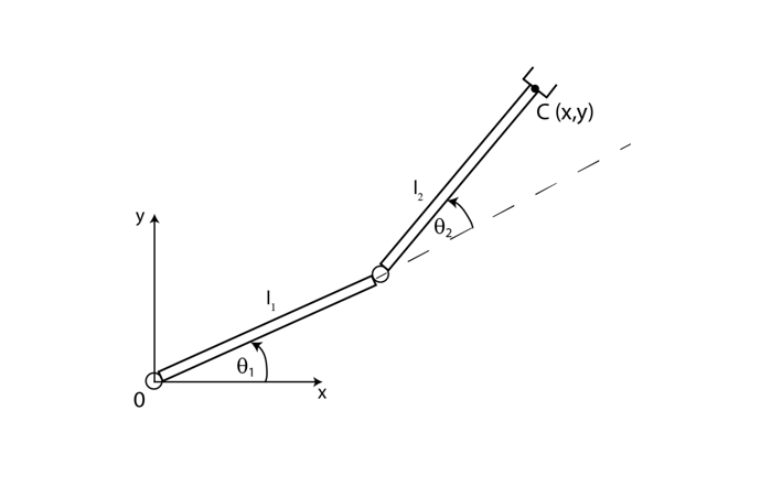
다음은 CCW 방향을 (+) 방향으로 하는 기본적인 2링크 모델이다. 이 때 점 P의 좌표를 두 각도에 대한 함수로 나타낼 수 있다.
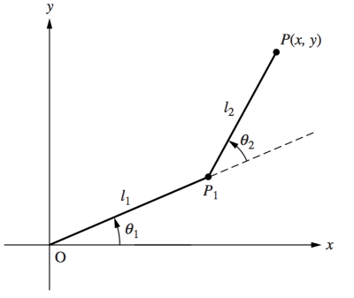
P1x=l1cosθ1,
P1y=l1sinθ1
∴x=l1cosθ1+l2cos(θ1+θ2),
y=l1sinθ1+l2sin(θ1+θ2)
2. 2링크의 Inverse Kinematics
이제 Forward Kinematics의 수식으로부터,
θ1(x,y),θ2(x,y)
를 구하면 된다.
x2=l12cos2θ1+l22cos2(θ1+θ2)+2l1l2cosθ1cos(θ1+θ2),
y2=l12sin2θ1+l22sin2(θ1+θ2)+2l1l2sinθ1sin(θ1+θ2)
−>x2+y2=l12+l22+2l1l2[C1(C1C2−S1S2)+S1(S1C2+C1S2)],
=l12+l22+2l1l2[C12C2−C1S1S2+C2S12+C1S1S2],
∴x2+y2=l12+l22+2l1l2cosθ2,
−>cosθ2=2l1l2x2+y2−l12−l22(−1,1),
sinθ2=±1−cos2θ2
여기서 잠깐 가능한 링크의 배치를 생각해보자.
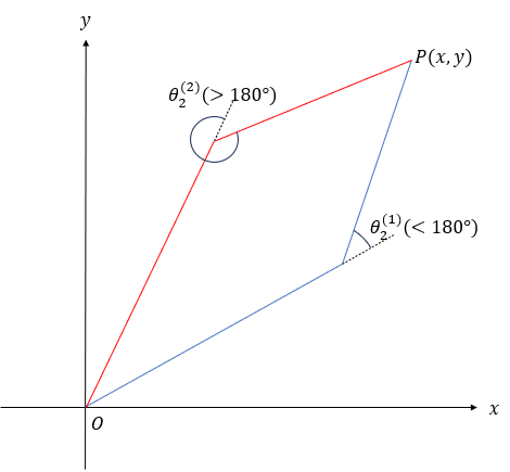
한 점 P에 대해, 링크가 쭉 펴지지 않았다면 해는 두 개가 존재한다.
링크2가 위로 굽어질 때를 양의 각도, 아래로 굽어질 때를 음의 각도로 정의하면,
θ2=atan2(cosθ2,sinθ2),
(cosθ2=2l1l2x2+y2−l12−l22,sinθ2=±1−cos2θ2)
이제 θ1을 구하기 위해서는 먼저 식을 정리해야 한다.
앞서,
x=l1c1+l2c12
y=l1s1+l2s12
이 식을 보다 단순한 형태로 바꾸기 위해서,
k1=l1+l2c2,
k2=l2s2
를 대입하면,
x=l1c1+l2(c1c2−s1s2)=k1c1−k2s1
y=l1s1+l2(s1c2+c1s2)=k1s1+k2c1
위 결과가 삼각함수 덧셈정리와 비슷해보인다면 의도된 것이다.
각각 코사인과 사인의 덧셈정리와 유사한 형태이다.
이를 이용해 k1,k2 가 각각 코사인값, 사인값인 것으로 가정할 것이다.
k1=rcosγ
k2=rsinγ
r=k12+k22
따라서, γ는 다음과 같이 정의된다.
γ=atan2(k1,k2)
다시 x,y로 돌아와서, 새로운 k1,k2의 형태를 대입하면,
rx=cosγcosθ1−sinγsinθ1=cos(γ+θ1),
ry=cosγsinθ1+sinγcosθ1=sin(γ+θ1)
정리하면,
γ+θ1=atan2(y,x),
γ=atan2(k2,k1)
따라서,
θ1=atan2(y,x)−atan2(k2,k1)
3. 그래서 어떻게 쓸 것인가?
2DOF Inverse Kinematics의 결과물은,
θ2=atan2(cosθ2,sinθ2),
θ1=atan2(y,x)−atan2(k2,k1)
이때,
cosθ2=2l1l2x2+y2−l12−l22,sinθ2=±1−cos2θ2 사인값의 부호는 사용자가 원하는 대로 결정
k1=l1+l2c2
k2=l2s2
- 사용할 로봇의 바디를 링크와 조인트로 단순화 한다.
- 좌표계를 설정한다. 이 때, 첫 번 째 링크의 가동범위를 신경써서, '중간 위치'를 각도 0으로 두는 것이 쉽다.
- 매니퓰레이터의 위치를 글로벌 좌표계 상에서의 좌표값으로 궤적을 만들고, Inverse Kinematics를 수행하면, 각 조인트의 각도는 자동으로 계산되어 나온다.
이 때, cosθ2가 (−1,1)를 벗어난다면, 갈 수 없는 위치이다.
atan2, sqrt 등의 함수는 C++의 경우 cmath.h
Python의 경우 math가 필요하다