In this section, I will post about single clock cycle datapath concept.
Single clock cycle concept is the instruction is executed in one clock cycle in single clock cycle CPU.
There are four generic implementations.
- Use the program counter to supply instruction address.
- Get the instruction from memory.
- Read registers.
- Use the instruction to decide exactly what to do
-> It means that we have to decide the purpose of instruction.
These are important concept in MIPS Architecture.
Add Operation

Sub Operation
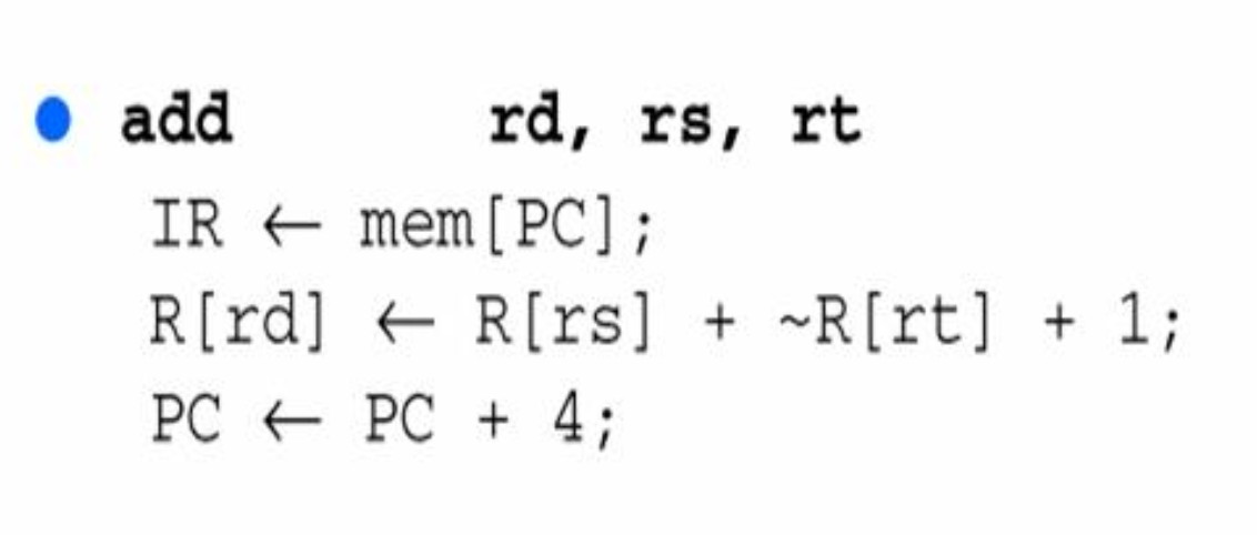
If we do subtraction, we must use 2's complement. Because in the MIPS Architecture, there is no unit of subtraction.
Load Word Operation
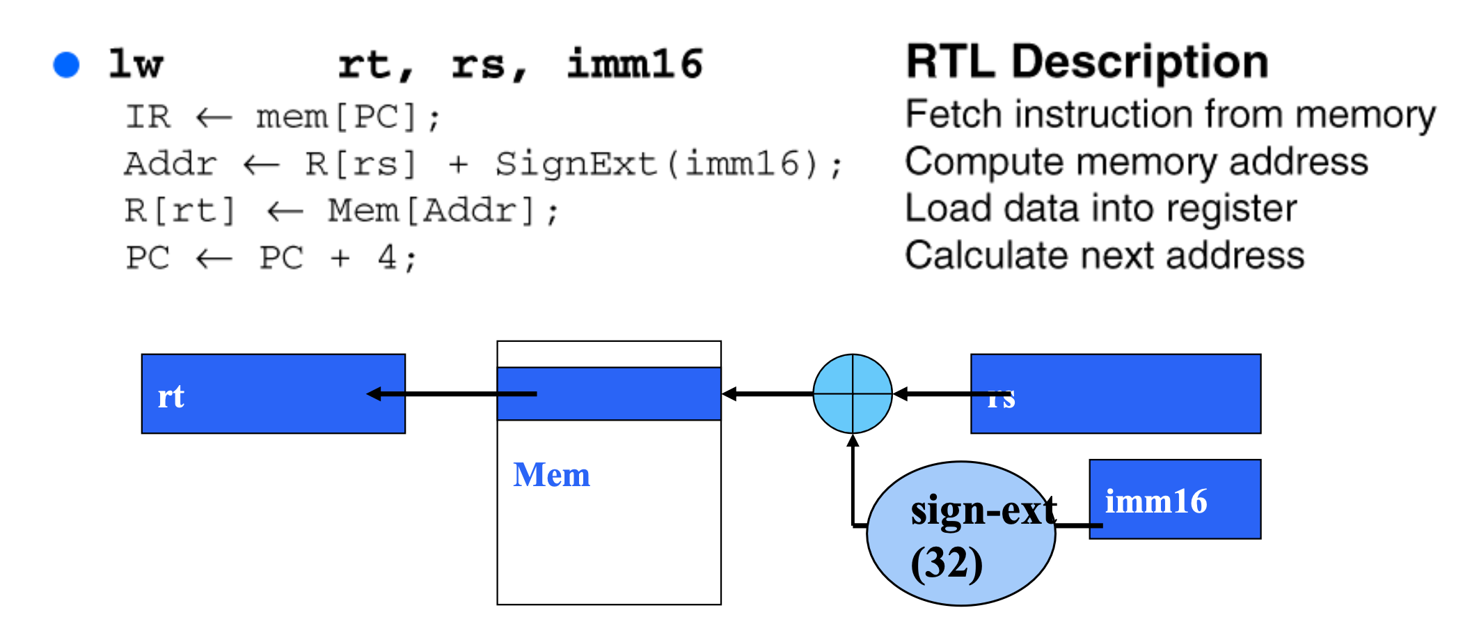
In this instruction, we have to do Sign Extention. Because there is 16 bits constant.
Store Word Operation
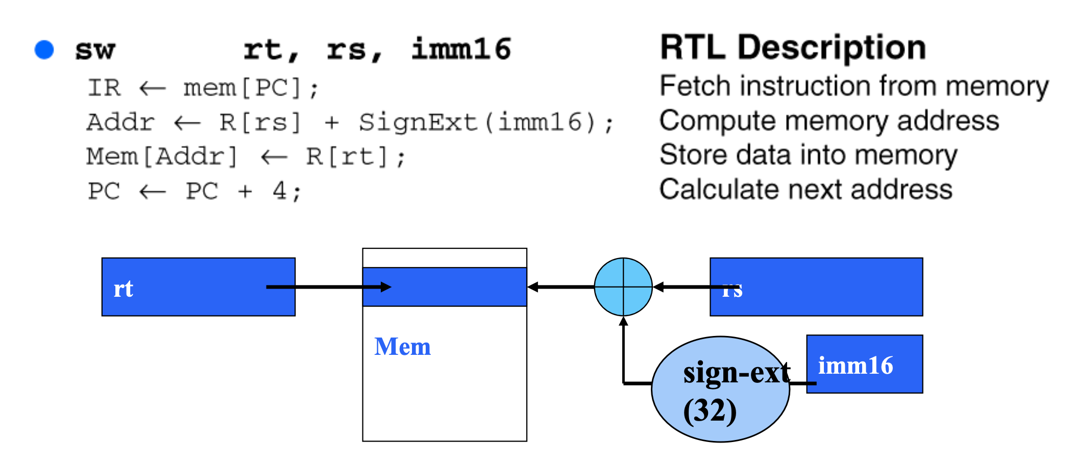
This instruction similar with Load Word Operation.
BEQ Operation
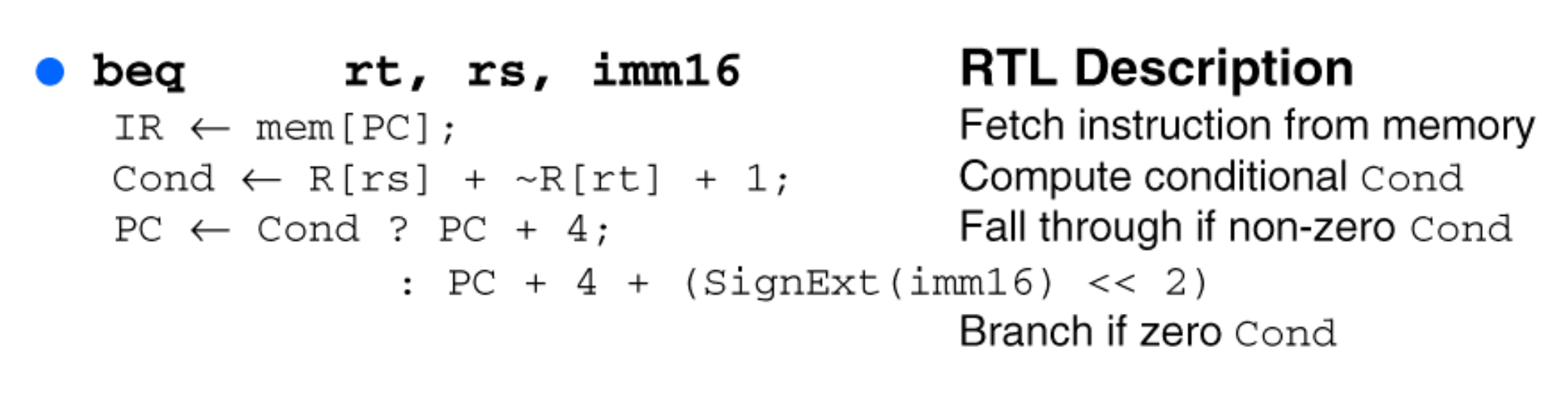
In this instruction, we have to make comparison with rt register and rs register. If R[rs] + ~R[rt] + 1 is 0, then we can regard as rs and rt is same.
Structure of Single Clock Cycle Unit
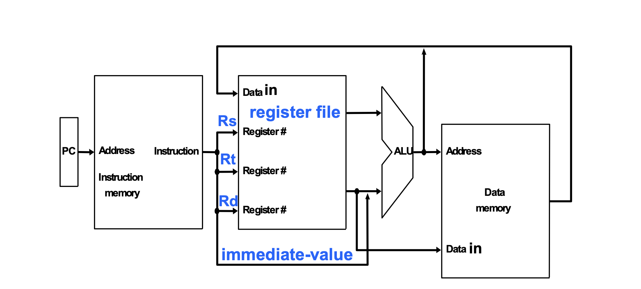
In the Single Clock Cycle Unit, we have to seperate the memory, instruction and data. Because this structure has just one clock cycle. If the memory is not seperated, we can't petch instruction and load data in the same time.
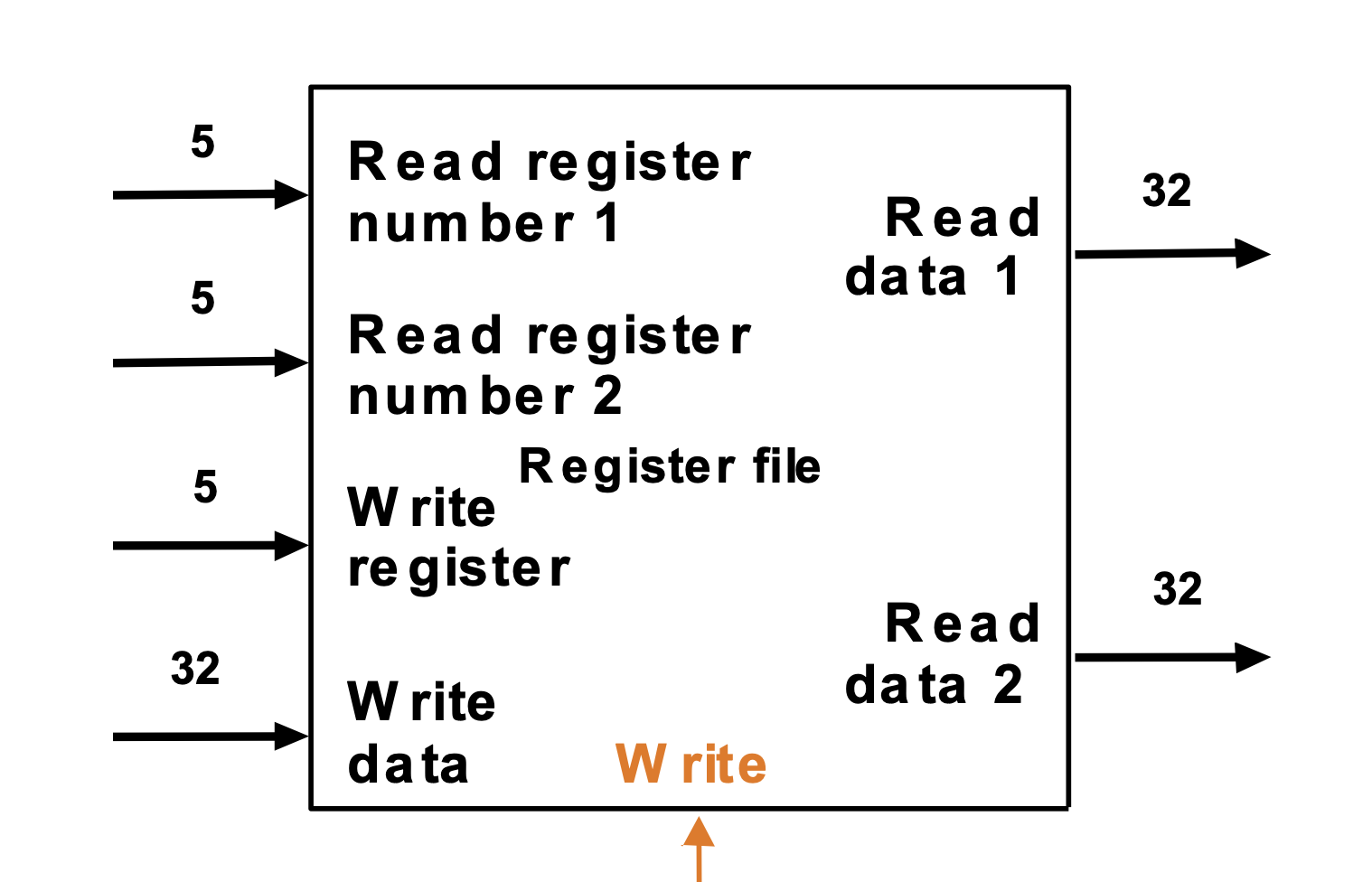
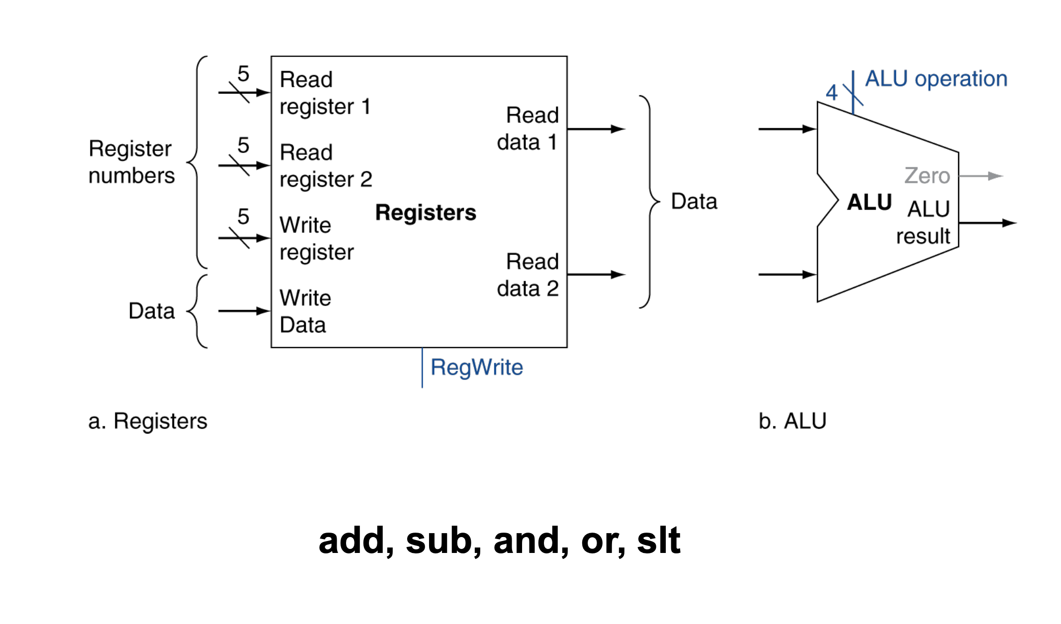
We can use D Flip-Flops. Read register number 1 and 2 is 5 bits. Because in the R-type instruction, there are three register sections with each bits 5. Read data 1,2 and write data are real value of the data, so we have to express it with 32bits.
After calculating in ALU, there is a result, write data, by using write register, we have to do SW instruction. If the Write value is enable, we have to do SW instruction. If it is 0, we can't.
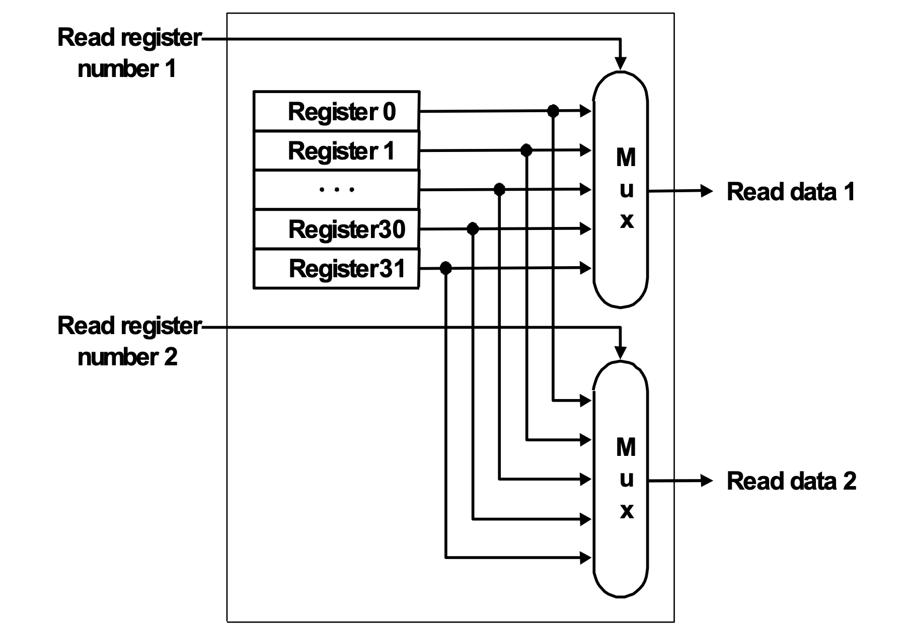
This is the read section.
The value of read register 1 and 2 is 5 bits. So, we have 32 register to use. To decide what register use, we can use MUX(32 -> 1).
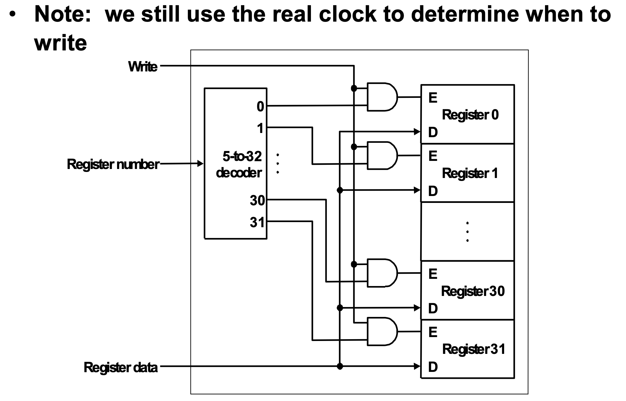
This is the write section.
After instruction is evaluated, we have to use 5-to-32 decoder to decide what register use. Next, if the write is enable, then register is selected.
Each register has two section E and D, D is register data section. It means that data is supplied always. The important point is E.
After selecting register, the corresponding register's E is enabled.
Finally, we can use write action.
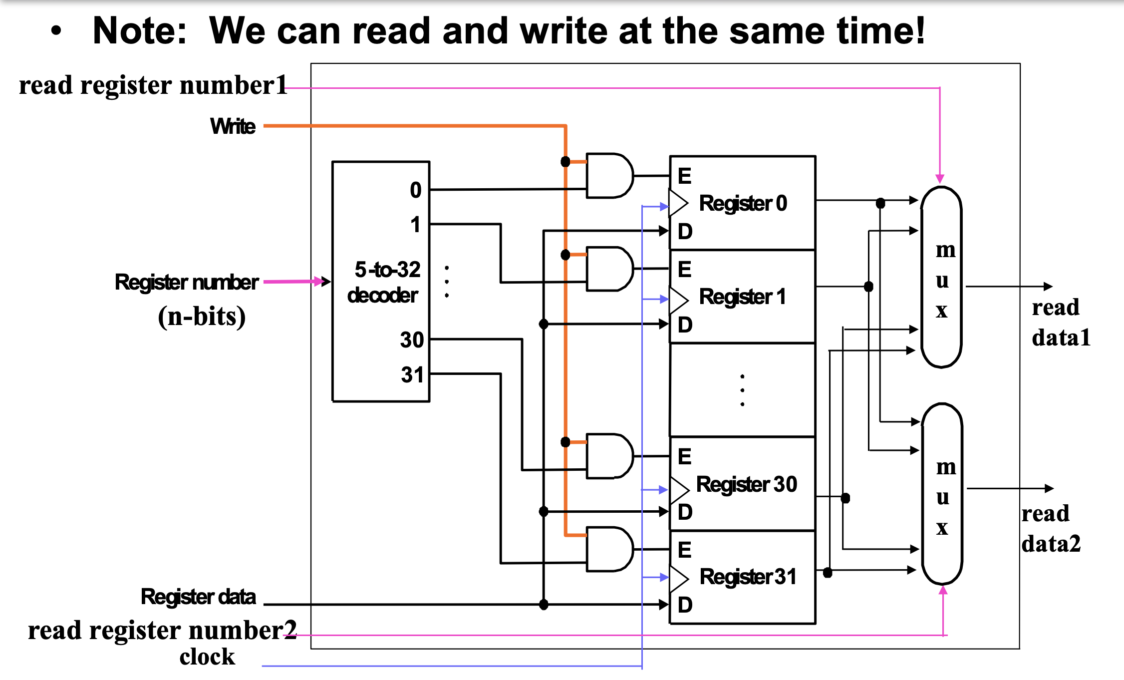
This picture is whole process of read and write. We can use read and write at the same time.
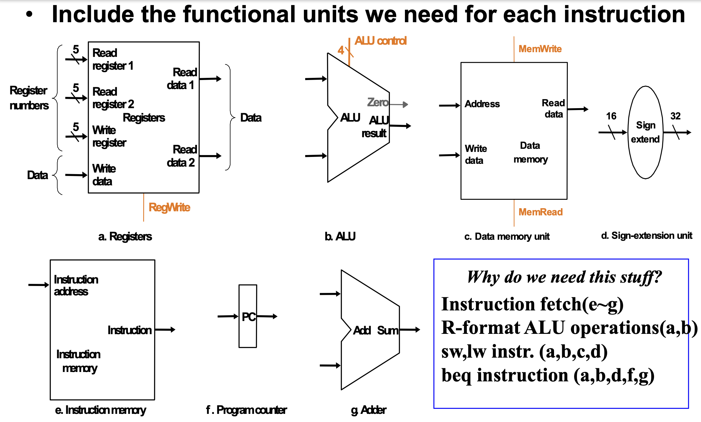
In this picture, we can see there are duplicated units ALU and Adder. What is the reason?
The answer is PC(Program Counter). We have to increase the value of PC, and also we have to evaluate instruction with ALU logic unit at the same time.
For that reason, Single Clock Cycle Unit must have these duplicated units.
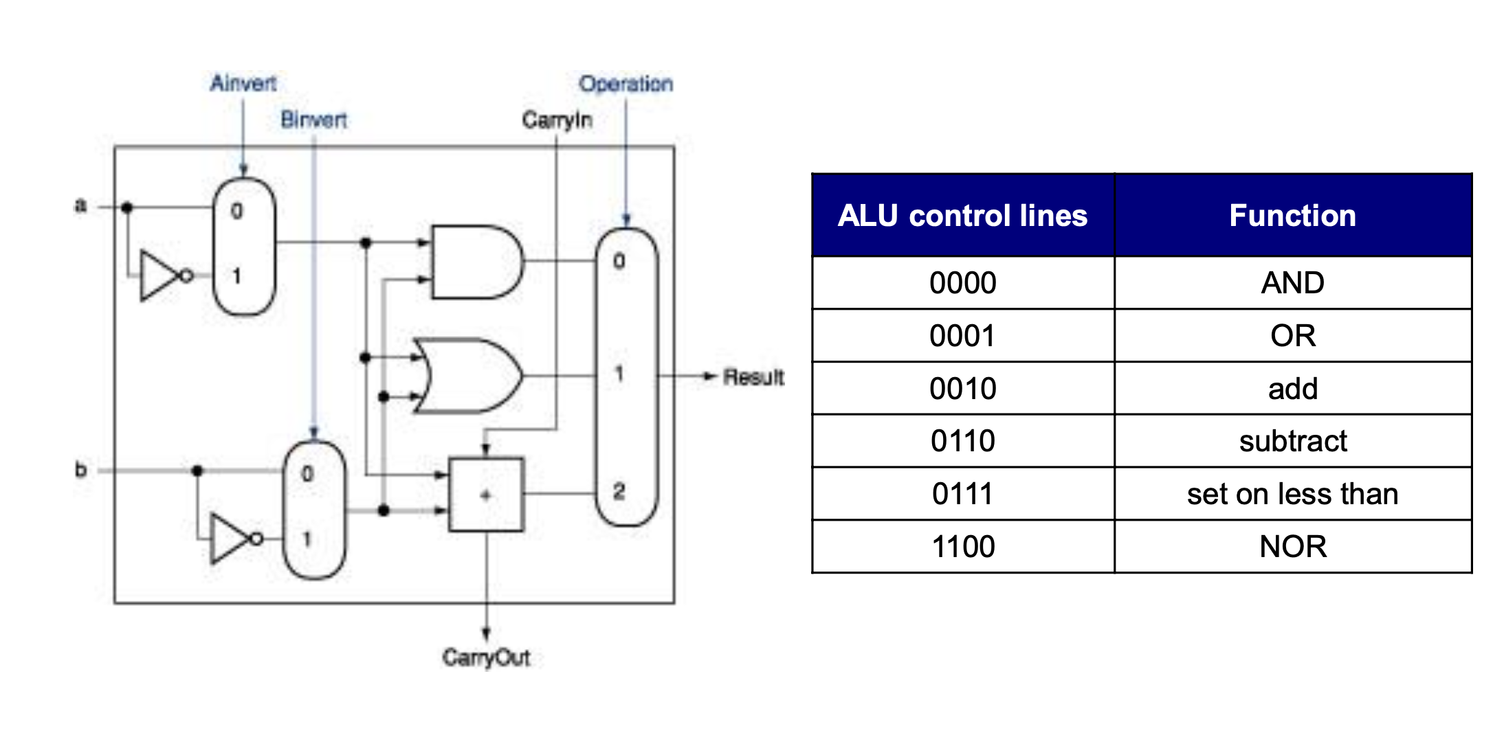
This is the architecture of ALU unit. There is Operation section it decided what instruction is executed. Each value of operation are coressponding with functions. So, we can use AND, OR, etc.
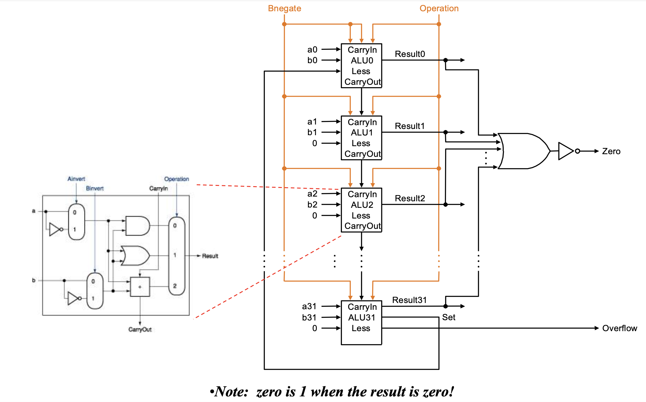
Zero is a status bit. It represents the status that result is 0 or not. There are 32 ALU units and the operation is supplied each of them. Finally, the result is supplied in the OR gate in front of the Zero bit.
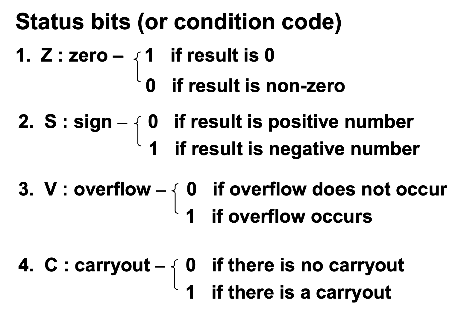
There are four types of status bits. By using them, we can know what status is.
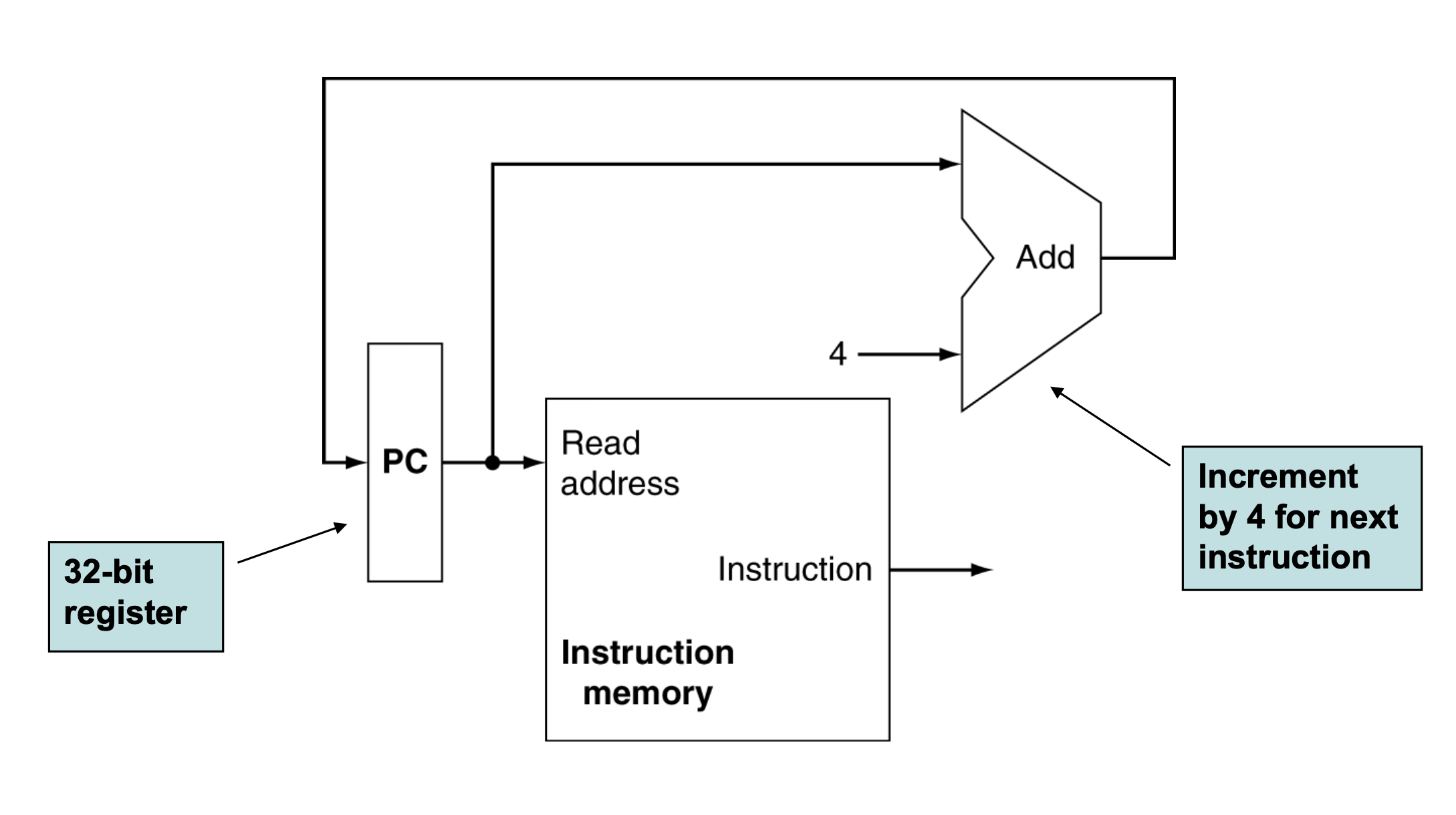
After instruction is executed, we have to increase the value of PC to PC + 4. So, automatically Adder adds 4 with PC. Because of that, we can access the next instruction.
Summary
We can use R-type instruction with D flip-flop and ALU units. We can use Zero status bit and ALU result.
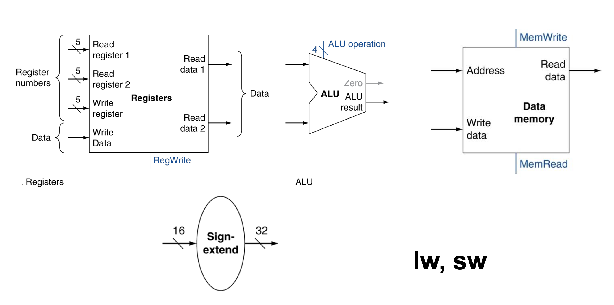
In addition, we can use lw, sw instructions. Because in the these instructions, we have to use constant with 16 bits. However, we use 32 bits sized register, so we have to do sign-extention.
The ALU results is used in write section. We can store the result in destination register.
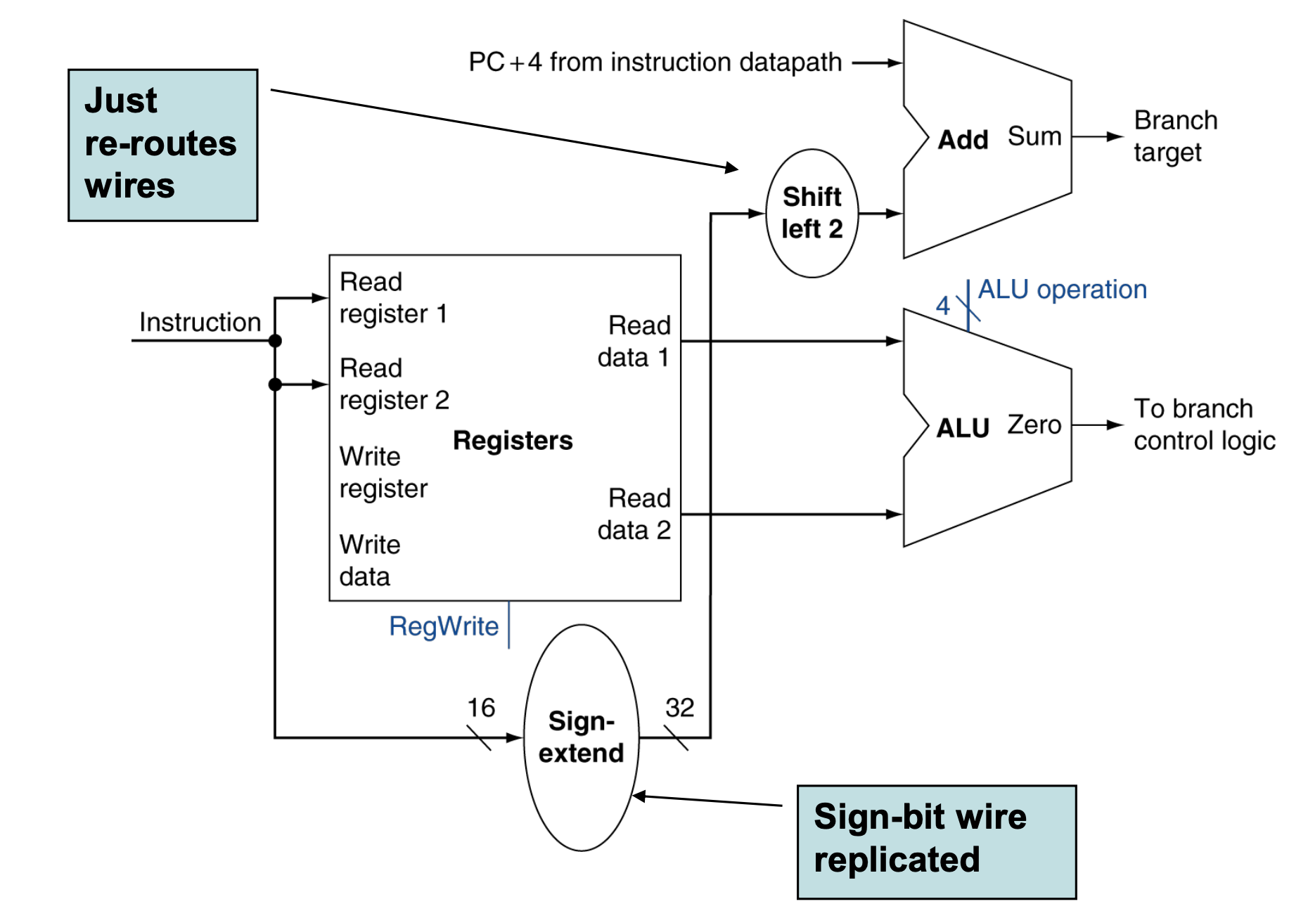
And also we can use branch instruction. We have two add unit, one is used to increase PC value, other is used to evaluate instruction. If the instruction is branch instruction, then there is constant of Label.
After shift left twice, if its value is added with PC + 4, then we can jump Label place.
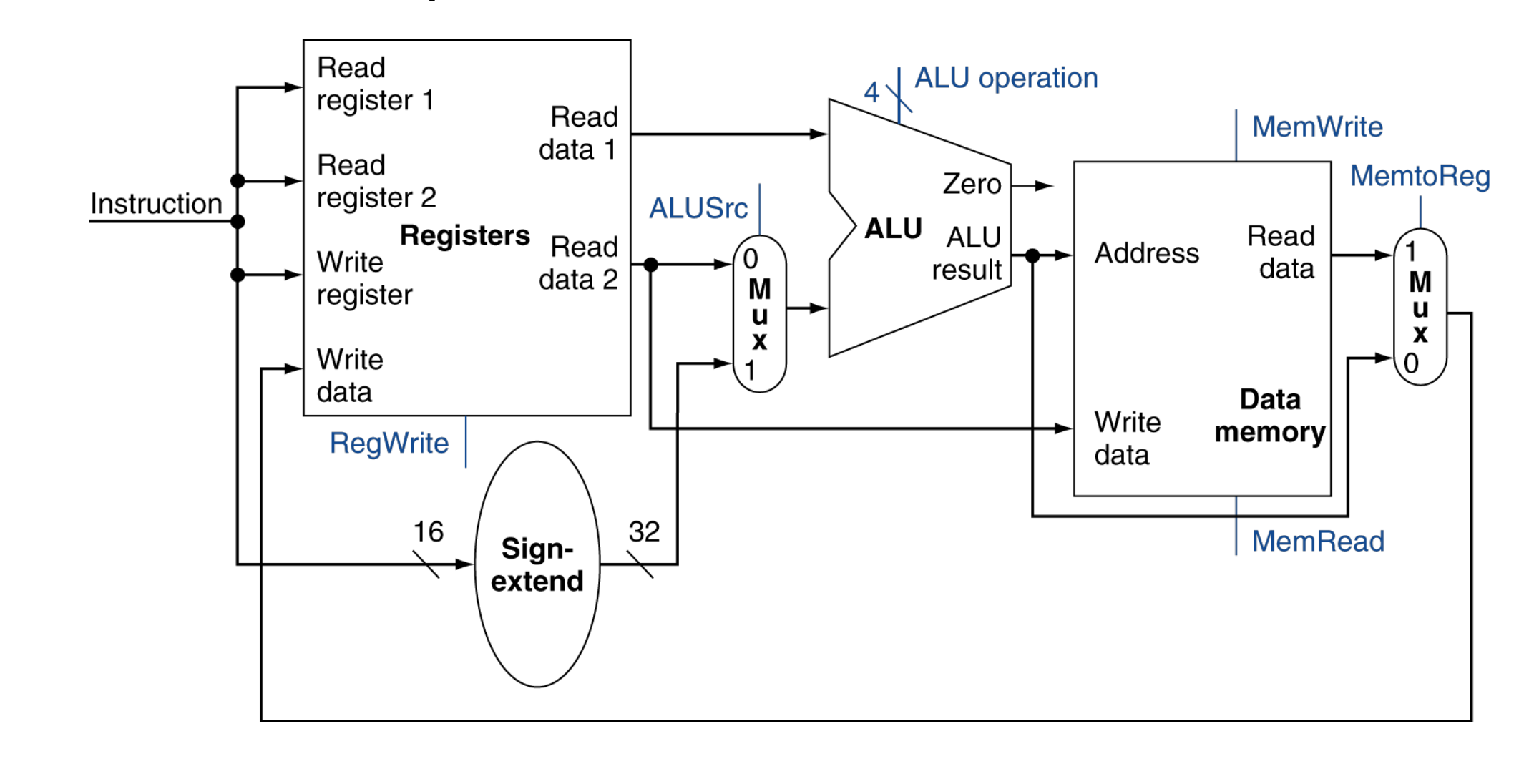
This is the final version of Single Clock Cycle Unit. By using this structure, we can use R-type instruction and LW, SW, Branch instructions.